STUDIODUE nanospot User manual

User’s and operator’s manual for art. 0801 and art.08011
Manuale d’uso e dell’operatore per art. 0801 e art.08011

This page is intentionally left blank

1Rel.1/04.08
Safety information:
Precauzioni di sicurezza: ......................................................... pag. 2
Technical features:
Caratteristiche tecniche: .......................................................... pag. 4
Main supply connection:
Collegamento fonte di alimentazione: .................................... pag. 5
DMX signal connection:
Collegamento segnale DMX: ................................................... pag. 5
Setting:
Settagggio: .............................................................................. pag. 6
Connection of DMX controller to spot:
Collegamento centralina DMX-fari: ...................... pag. 7
DMX Listing:
Lista dei valori DMX: ................................................................ pag. 8
Service:
Servizio: .................................................................................... pag. 9
Built in programmes:
Lista dei giochi: ......................................................................... pag. 10
Electric diagrams:
Schemi elettrici: ......................................................................... pag. 10
INDEX / INDICE
2
Rel.1/04.08
eng
WARNING
SAFETY INFORMATION (service personnel)
READ ALL CAUTIONS AND WARNINGS PRIOR TO OPERATE THIS EQUIPMENT.
INSTRUCTION TO PREVENT INJURY OR DAMAGE DUE TO ELECTRIC SHOCK, FIRE, MECHANICAL HAZARDS,
DANGEROUS MATTERS.
•PROTECTION AGAINTS FIRE
1) Maintain minimum distance of 0.3 meter from walls or any other flammable surfaces.
2) Maintain minimum distance of 0.5 meter to other illuminated objects .
3) Replace fuses (if present) only with the specified type and rating.
4) Do not install the spot close to heat sources. Do not lay the connection cable on the spot when it is warm.
5) Fixture designed to be installed on normally flammable surfaces.
•PROTECTION AGAINST ELECTRIC SHOCK
1) This equipment must be earthed.
2) Class I equipment. The power supply cord includes a protective earthing conductor as part of the cord.
3) Disconnect power before servicing (service personnel).
•PROTECTION AGAINST MECHANICAL HAZARDS
1) Use secondary safety chain when fixing this equipment.
2) Equipment surface may reach temperature up to 40°C.
•PROTECTION AGAINST DANGEROUS MATTERS
At the end of its working life, the product must not be disposed of as urban waste. It must be taken to a special local autho-
rity waste collection centre or to a dealer providing this service. The wrong disposal will cause pollution and environmental
damages in the presence of possible dangerous materials.
0,5m
F
INFORMAZIONI DI SICUREZZA (personale di servizio)
LEGGERE ATTENTAMENTE TUTTI GLI AVVERTIMENTI PRIMA DI COMPIERE QUALUNQUE OPERAZIONE SU QUESTO
APPARECCHIO. ISTRUZIONI PER PREVENIRE LESIONI O DANNI DOVUTI AL FUOCO, ALLE SCOSSE ELETTRICHE,
AI RISCHI MECCANICI ED A SOSTANZE PERICOLOSE.
•PROTEZIONE CONTRO IL FUOCO
1) Mantenere la distanza minima di 0.3 metri da pareti ed altre superfici infiammabili.
2) Mantenere la distanza minima di 0.5 metri dagli oggetti illuminati.
3) Sostituire i fusibili (se presenti) solo con altri dello stesso tipo e valore.
4) Non installare il faro vicino fonti di calore. Non appoggiare il cavo di connessione sul faro quando questo è caldo.
5) Questo apparecchio è adatto per il montaggio su superfici normalmente infiammabili.
•PROTEZIONE CONTRO SCOSSE ELETTRICHE
1) Questo apparecchio necessita di messa a terra.
2) Apparecchio di Classe I. Il conduttore di protezione deve far parte del cavo di alimentazione.
3) Disconnettere l’alimentazione prima di aprire l’apparecchio (personale di servizio).
•PROTEZIONE CONTRO RISCHI MECCANICI
1) Usare la catena di sicurezza supplementare quando installate il faro.
2) La temperatura dell’apparecchio può raggiungere 40°C.
IMPORTANTE
•PROTEZIONE CONTRO SOSTANZE PERICOLOSE
Questo prodotto a fine vita è oggetto di raccolta separata, non gettare nei comuni cassonetti di rifiuti urbani, né
tantomeno nell’ambiente. Può essere consegnato presso gli appositi centri di raccolta differenziata predisposti dalle
amministrazioni comunali, oppure presso i rivenditori che forniscono questo servizio. Lo smaltimento errato può cau-
sare danni alle persone e all’ambiente per la possibile presenza di sostanze pericolose. Sono previste sanzioni in caso
di smaltimento abusivo dei suddetti prodotti.
F
0,5m
ita
3Rel.1/04.08
YOUR REFERENCE
Always remeber to give the serial number and to specify the model any time you address the seller for information or assistance.
BASIC KIT
The basic kit of the NanoSpot consists of:
•Projector
•User’s manual
•Studio Due warranty
AVAILABLE VERSIONS
Art. 0801 RGB NanoSpot/C
Art. 08011 W+A NanoSpot/C (white+amber)
WARNING
Check that the spot has not been damaged during transportation. If it has been damaged or it does not work,
address the seller. If the spot has been shipped to you directly, please contact the shipping company.
Only the consignee (person or company) can claim for these damages.
INTRODUCTION
Thanking for choosing NanoSpot.
NanoSpot is designed with a charming and chromatic housing applicable for various applications.
The latest and reliable electronic circuit enables the fixtures to perform with stability.
To make the most of its possibilites and for a correct functioning of this unit in the years to come, we suggest you to read carefully
this manual before connecting or putting the spot into use. By doing so you will gain experience with its commands and connections
and you will be easily able to use it.
INTRODUZIONE
Vi ringraziamo per aver scelto NanoSpot.
Caratterizzato da un design accattivante e da una resa cromatica incredibile, il NanoSpot si inserisce elegantemente in ogni tipo di
ambiente. Un circuito elettronico moderno ed affidabile ne garantisce stabilità e sicurezza di funzionamento per lungo tempo.
Per ottenere il meglio delle prestazioni ed un corretto funzionamento negli anni di questa unità, Vi consigliamo di leggere attenta-
mente questo manuale prima di collegarla e metterla in uso. In questo modo acquisirete familiarità con i suoi comandi e collegamenti
affinché possiate facilmente utilizzarla.
VOSTRA REFERENZA
Citate il numero del modello e di serie ogni volta che Vi rivolgete al vostro rivenditore per informazioni o assistenza.
CONFEZIONE BASE
La confezione base del proiettore NanoSpot contiene:
•Proiettore
•Manuale d’uso
•Garanzia Studio Due
VERSIONI DISPONIBILI:
Art. 0801 RGB NanoSpot/C
Art. 08011 W+A NanoSpot/C (bianco+ambra)
Controllate che l’apparecchio non abbia subito alcun danno durante il trasporto.
Se avesse subito dei danni o se non dovesse funzionare, rivolgetevi al vostro rivenditore.
Se l’apparecchio vi è stato spedito direttamente, rivolgetevi subito alla ditta di trasporto.
Solo il destinatario (la persona o ditta ricevente l’apparecchio) può reclamare per questo tipo di danni.
IMPORTANTE
eng
ita
4
Rel.1/04.08
TECHNICAL FEATURES / CARATTERISTICHE TECNICHE
RGB HI-POWER HIGH EFFICIENCY 3W LEDS
WHITE + AMBER HI-POWER HIGH EFFICIENCY 3W LEDS
LEDS / LED
4 RED leds 3W (each) total 240 lumen
5 GREEN leds 3W (each) total 440 lumen
5 BLUE leds 3W (each) total 150 lumen
Totale LUMEN 830 lumen (RGB)
CONTROL INPUT / SEGNALE DI CONTROLLO
Standard interface RS-485, opto-coupled input, protocol: USITT DMX 512.
interfaccia standard RS-485, ingresso opto-isolato, protocollo: USITT DMX 512.
COLOUR / COLORI
RGB or WHITE+AMBER
RGB o BIANCO+AMBRA
STROBE/BLACKOUT/DIMMER
Blackout and strobe effect with linear speed. (min. 0.4 flash/sec. max. 25 flash/sec.) + dimmer: 0÷100%
Oscuramento con effetto strobo a frequenza regolabile (min. 0.4 flash/s max 25 flash/s) + funzione dimmer 0÷100%
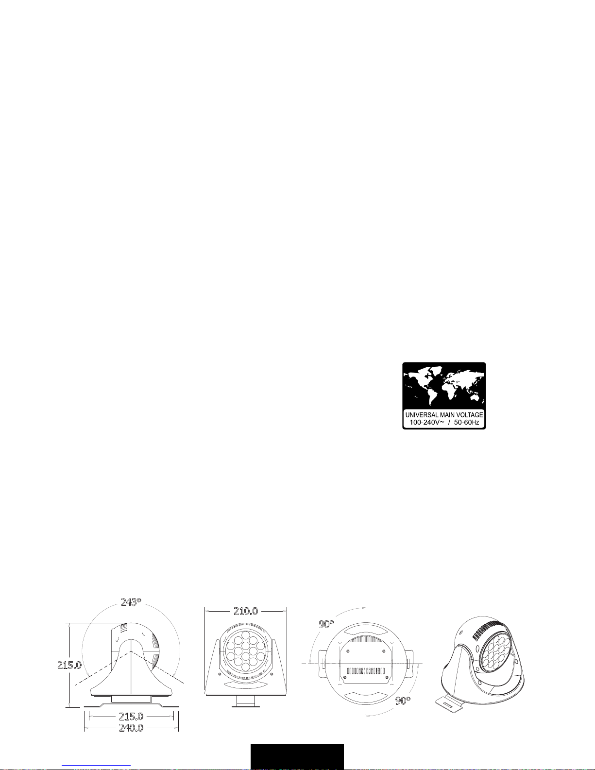
MOVEMENT / MOVIMENTO
Pan 180°. Tilt 243°
Pan 180°. Tilt 243°
AUTO MODE / MODO AUTOMATICO
With Master/Slave functions / con funzione Master/Slave
MAIN POWER SUPPLY / ALIMENTAZIONE
Electronic switching power supply / alimentatore elettronico universale
• Rated voltage / Tensione di rete : 100-240~/ 50-60 Hz
• Rated wattage / Assorbimento : 40 VA Fuse: 1 AT
• Rated current / Assorbimento : 0,5A-0,25A
WEIGHT / PESO : 2.8 KG NET
DIMENSION / DIMENSIONI: (WxDxH) 240x215mm

5Rel.1/04.08
CONNECTION TO THE MAIN POWER / CONNESSIONE ALLA RETE ELETTRICA
This equipment must be earthed.
Class I equipment. The power supply cord includes a protective earthing conductor as part of the cord.
Questo apparecchio necessita di messa a terra.
Apparecchio di Classe I. Il conduttore di protezione deve far parte del cavo di alimentazione.
eng
ita
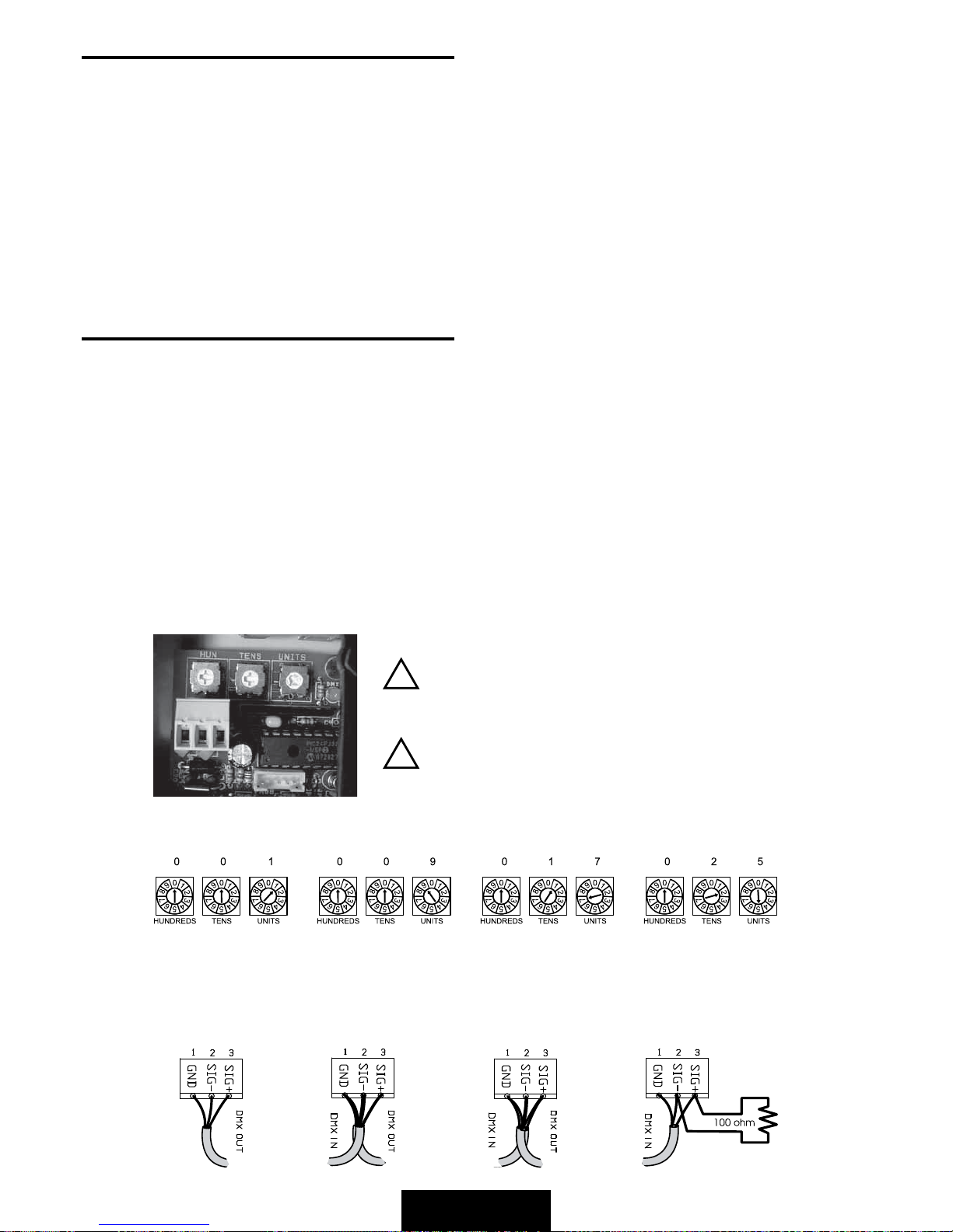
DMX TERMINAL LINE
The wrong connection of the terminal line or its non-connection are probably the most frequent reason for the defective functioning of the DMX
line. The terminator is a terminal resistor fitted at the end of the cable furthest from the transmitter.
The terminal resistor should have the same value as the impedance of the connection cable.
We suggest to use a terminal with a 100 ohm resistor.
It is recommended that all DMX 512 system has the terminal resistor fitted in the DMX output of the last fixture.
TERMINALE LINEA DMX
L’incorretto o il mancato collegamento del terminale di linea è probabilmente la più comune causa del difettoso funzionamento della linea DMX.
Il terminale di linea DMX consiste in una resistenza posta alla fine della linea.
La resistenza terminale dovrebbe avere idealmente lo stesso valore dell’impedenza del cavo di collegamento.
Noi consigliamo di usare come terminale una resistenza da 100 ohm.
E’ raccomandato per tutti i sistemi DMX 512 inserire il teminale di linea nel connettore uscita DMX dell’ultimo apparecchio collegato.
eng
ita
DMX CONNECTION / CONNESSIONE DMX
MAIN POWER CONNECTION
FBrown
GND Black\Yellow
NBlue
The fixture is already wired
L’apparecchio è già cablato
WARNING
IMPORTANTE
FUSE:
The fuse must be replaced from
service personnel only.
FUSIBILE:
Il fusibile deve essere sostituito
solamente da personale di servizio.
DMX signal LED
LED presenza segnale DMX
6
Rel.1/04.08
DMX 512 CONTROL
1) Connect the DMX data cable coming from the controller to the DMX-IN connector on the electronic board (see pict. below).
2) Select the DMX starting address by operating on the rotary switches (UNITS, TENS, HUNDREDS).
AUTO - MODE CONTROL
1) Set n° 6 on the HUNDREDS rotary switch (MASTER).
2) Choose the games (see page 10) by operating on the UNITS and TENS rotary switches.
SYNCHRO - MODE CONTROL
1) Interconnect all the fixtures (max 32) by using the DMX standard cables.
2) Set the first fixture as MASTER by setting n° 6 on the HUNDREDS rotary switch.
3) Choose the games by operating on the UNITS and TENS rotary switches (on MASTER fixture).
4) Set all the rest of the fixtures as SLAVE by setting n° 7 on the HUNDREDS rotary switch.
If you set the dip switches on 000 you have the TEST function.
CONTROLLO CON CENTRALINA DMX 512
1) Collegare il cavo DMX proveniente dalla centralina all’ingresso (DMX-IN) sulla scheda elettronica (vedere figura in basso).
2) Selezionare il canale DMX di partenza dell’apparecchio agendo sui commutatori rotativi (UNITA’, DECINE, CENTINAIA).
CONTROLLO IN MODO AUTOMATICO
1) Selezionare il n° 6 sul commutatore rotativo delle CENTINAIA (MASTER).
2) Scegliere i giochi (vedere pag. 10) agendo sui commutatori rotativi delle DECINE e delle UNITA’.
CONTROLLO IN MODO SINCRONO
1) Interconnettere tutti gli apparecchi (massimo 32) tramite le prese DMX-IN usando un cavo DMX standard.
2) Settare il primo apparecchio come MASTER selezionando il n° 6 sul commutatore rotativo delle CENTINAIA.
3) Scegliere sull’apprecchio MASTER il gioco agendo sui commutatori rotativi delle DECINE e delle UNITA’.
4) Settare tutti gli altri apparecchi come SLAVE selezionando su ognuno di essi il n° 7 sul commutatore rotativo delle CENTINAIA.
Selezionando i commutatori su 000 effettuate l’AUTOTEST.
eng
ita
Spot n° 1
Faro n° 1
Spot n° 2
Faro n° 2
Spot n° 3
Faro n° 3
Spot n° 4
Faro n° 4
Channel 1-8
Canale 1-8
Channel 9-16
Canale 9-16
Channel 17-24
Canale 17-24
Channel 25-32
Canale 25-32
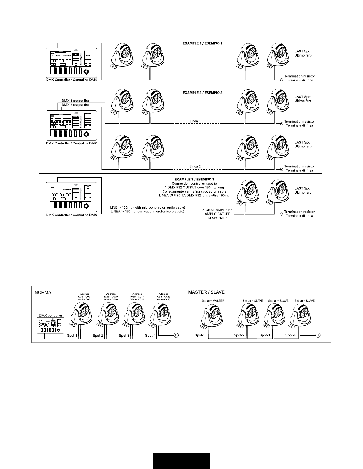
EXAMPLE OF CONNECTION OF 4 NANOSPOT IN SYNCHRO-MODE
ESEMPIO DI COLLEGAMENTO DI 4 NANOSPOT IN MODO AUTOMATICO SINCRONIZZATO
IMPORTANTE
WARNING
HIGH VOLTAGE!
Always disconnect the mains supply before
access to the connection area.
ALTA TENSIONE!
Scollegare sempre l’alimentazione prima di
aprire il vano dei collegamenti
7Rel.1/04.08
EXAMPLE OF CONNECTION DMX CONTROLLER TO SPOT / ESEMPIO DI COLLEGAMENTO CENTRALINA-FARI
NORMAL OR MASTER-SLAVE FUNCTION/ ESEMPIO DI FUNZIONAMENTO NORMALE O MASTER-SLAVE
8
Rel.1/04.08
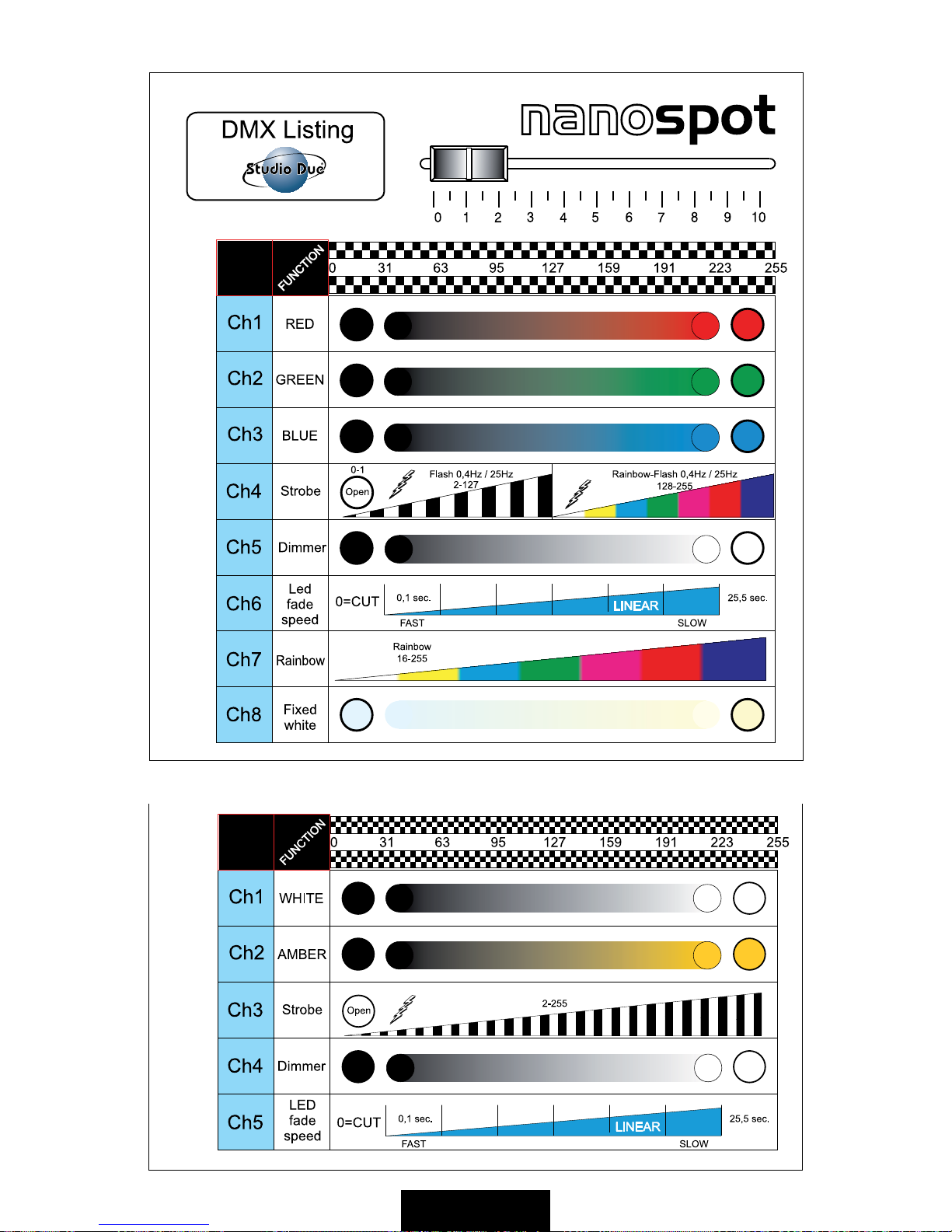
DMX Listing (RGB) / Lista dei valori DMX (RGB)
DMX Listing (WHITE+Amber) / Lista dei valori DMX (WHITE+Ambra)

9Rel.1/04.08
SERVICE

10
Rel.1/04.08
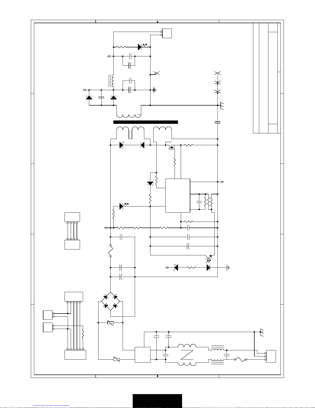
ELECTRIC DIAGRAM / SCHEMI ELETTRICI
BUILT IN PROGRAMMES/LISTA DEI GIOCHI
PROGRAM FUNCTION
01 FIXED RED
02 FIXED GREEN
03 FIXED BLUE
04 RED -> GREEN -> BLUE -> RED+GREEN -> RED+BLUE -> GREEN+BLUE -> RED+GREEN+BLUE (step time 3 sec.)
05 RED -> GREEN -> BLUE -> RED+GREEN -> RED+BLUE -> GREEN+BLUE -> RED+GREEN+BLUE (step time 5 sec. + 2.5 sec. fade)
06 RAINBOW SLOW
07 RAINBOW MID
08 RAINBOW FAST

11 Rel.1/04.08
' '
& &
% %
$ $
81,76
7(16
+81'5(6
352*(08
6WXGLR'XH,7$/<
1$126327
$
:HGQHVGD\)HEUXDU\
7LWOH
6L]H 'RFXPHQW1XPEHU 5HY
'DWH 6KHHW RI
2372
9
9
2372
9
9
9
9
&
'
&
-3
7
&
4
5
&
5
5
&
8
+9
9GG
/'
9LQ*1'
&6
*DWH
5RVF
3:0
5
&
&
5
/
8
$
.
9&&
*1'
9%
92
/
&
&
-3
&
5
&
-3
5
5
'
&
<
5
-3
4
5
-3
8
5
5(
9&&*1'
'(
'
$
%
&
'
6
5
5
'
&
5
5
8
+9
9GG
/'
9LQ*1'
&6
*DWH
5RVF
3:0
&
5
4
37&
5
5
'
5
8
$
.
9&&
*1'
9%
92
'
&
5
5
5
'
5
5
5
&
&
&
-3
-3
&
5
5
=
5
5
8
9LQ 287
)%
*
*
*
&
&
&
&
6
8
3,&)-
0&/5
5$
5$
5%3*'
5%3*&
5%
5%
966
5$26&
5$26&
5%
5$
9''
5%
5%
5%
5%6&/
5%6'$
',695(*
9&$3
5%
5%
5%
5%
5%
5%
966
9''
'
37&
4
&
&
5
=
'
8
$
.
9&&
*1'
9%
92
-3
'
&
&
5
8
,1 287
*
8
+9
9GG
/'
9LQ*1'
&6
*DWH
5RVF
3:0
'
&
5
5
/
&
&
&
5
&
6
7(1
+81
81,
81,
7(1
+81
7(1
+81
81,
81,
7(1
+81
5;'
7;'
',5
3:0
3:0
287
3:0
287
+81
81,
81,
+81
+81
81,
7(1
7(1
+81
81,
7(1
7(1
3:0
3:0
3:0
5;'
',5
7;'
)$1B0&
287
287
287
)$1B0&
287
12
Rel.1/04.08
' '
& &
% %
$ $
;
; ;
;
;
6WXGLR'XH
1$126327
$
7KXUVGD\)HEUXDU\
7LWOH
6L]H 'RFXPHQW1XPEHU 5HY
'DWH 6KHHW RI
923
923
59
5
-3
'
5
&
-3
02725&211(&725
&
&
/
'
5
&
5
&
5
&
&
5
'
5
4
5
5
5
8
-3
&
&
-3
/('&211(&725
&
,62
-3
)
-3
'
-3
/
5
'
)
(0,B),/7(5
'
75
3
3
$
$
3
3
6
6
&
/
5
5
5
&
'
5
&
-3
)
)86(
-3
'
&
&
&
'
/
&
17&

13 Rel.1/04.08
NANOSPOT EXPLODED VIEW / ESPLOSO DISEGNO NANOSPOT
14
Rel.1/04.08
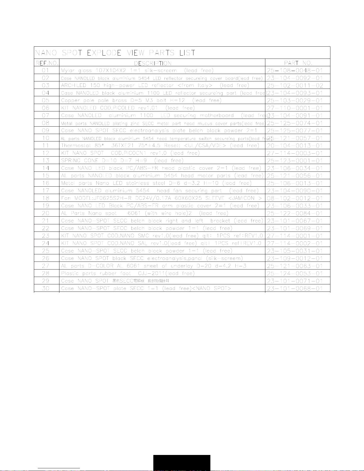
NANOSPOT SPARE PARTS / LISTA COMPONENTI NANOSPOT

15 Rel.1/04.08
Warranty CARD
WARRANTY / GARANZIA
&RPSDQ\QDPH
0U0UV0LVV
$GGUHVV
7HORU(PDLO
'HDOHU
16
Rel.1/04.08
Dichiarazione di conformità
Declaration of conformity
La ditta:
The firm:
dichiara sotto la propria responsabilità che il prodotto:
declare under our sole responsability that the product:
è conforme alle norme:
is in conformity with the standard:
RGB NANOSPOT
codice 0801
/C
e quindi ai requisiti essenziali delle Direttive:
and therefore according to essential requirement of Directives:
LV 73/23 AND 93/68 EEC
EMC 89/336 AND 93/68 EEC
VITERBO, 07/02/08
08
FRANCO BERTINI
General Manager
Data di apposizione :
Date of marking :
Doc. 0801-A REV 1 - 02/08
RGB NANOSPOT/C
02/08
EN 60598-1 Ed. VII (CEI 34-23 Ed. II)
EN 60598-2-17 Ed. II (CEI 34-38 II )Ed.
STUDIO DUE s.r.l.
Strada Poggino, 100
01100 VITERBO
ITALY
CEI EN 61000-3-2
CEI EN 61000-3-3
CEI EN 60065
CEI EN 55022
CEI EN 55011
CEI EN 55013
CEI EN 55015
CEI EN 55014-1
CEI EN 55013-1
CEI EN 61000-4-2
CEI EN 61000-4-4
CEI EN 61000-4-5
CEI EN 61000-4-6
CEI EN 61000-4-3
CEI EN 61000-4-11
CEI EN 55103-1
CEI EN 55103-2
17 Rel.1/04.08
Dichiarazione di conformità
Declaration of conformity
La ditta:
The firm:
dichiara sotto la propria responsabilità che il prodotto:
declare under our sole responsability that the product:
è conforme alle norme:
is in conformity with the standard:
W+A NANOSPOT
codice 08011
/C
e quindi ai requisiti essenziali delle Direttive:
and therefore according to essential requirement of Directives:
LV 73/23 AND 93/68 EEC
EMC 89/336 AND 93/68 EEC
VITERBO, 07/02/08
08
FRANCO BERTINI
General Manager
Data di apposizione :
Date of marking :
Doc. 08011-A REV 1 - 02/08
W+A NANOSPOT/C
02/08
EN 60598-1 Ed. VII (CEI 34-23 Ed. II)
EN 60598-2-17 Ed. II (CEI 34-38 II )Ed.
STUDIO DUE s.r.l.
Strada Poggino, 100
01100 VITERBO
ITALY
CEI EN 61000-3-2
CEI EN 61000-3-3
CEI EN 60065
CEI EN 55022
CEI EN 55011
CEI EN 55013
CEI EN 55015
CEI EN 55014-1
CEI EN 55013-1
CEI EN 61000-4-2
CEI EN 61000-4-4
CEI EN 61000-4-5
CEI EN 61000-4-6
CEI EN 61000-4-3
CEI EN 61000-4-11
CEI EN 55103-1
CEI EN 55103-2

Studio Due - ©
The features on this brochure are not binding: they can be changed without notice.
Le caratteristiche riportate su questo catalogo non sono impegnative: possono essere soggette a variazioni senza preavviso.
Head Office: STUDIO DUE s.r.l. (I)
Str. Poggino, 100 - 01100 Viterbo (Italy)
tel. +39.0761.352520
fax +39.0761.352653
www.studiodue.com
for technical info
STUDIO DUE Far East LTD (HK)
Unit 13 On 7th Floor, Heng Ngai Jewelry Centre,
4 Hok Yuen Street East
Hunghom, Kowloon, (Hong Kong)
tel. +852.29542141 fax +852.23302515
STUDIO DUE lighting technology (PRC)
Shen Zhen LTD (China)
STUDIO DUE (UK)
3 Encon Court Owl Close
Moulton Park Industrial Estate
Northampton England UK - NN3 6 HZ
tel. +44.1933.650.820
Table of contents
Other STUDIODUE Light Fixture manuals


Popular Light Fixture manuals by other brands


BoomToneDJ
BoomToneDJ atomic ball user manual

elektraLite
elektraLite MY 250 user manual

Flash butrym
Flash butrym LED MOVING HEAD 144W WASH user manual

LichtLogistik LED Support
LichtLogistik LED Support SlimPixx manual

EKVIP
EKVIP 021860 operating instructions

Nobile
Nobile SMD 2835 Mounting and operation instructions