VAXIS Thor 800FT+ User manual


Vaxis Thor 800FT+ Wireless Transmission System
User manual
1. Cautions....................................................................................................................................1
2. About......................................................................................................................................... 2
3. Setting UP............................................................................................................................ .. 5
4. Placement Guidelines and Best Practices............................................................ 10
5. Operation instruction...................................................................................................... 11
6. Maintenance.......................................................................................... 17

1
1. Cautions
■Logo and meaning
Careful, warning, dangerous, Pay attend to following items.
■Cautions
Do not use this product in the extreme hot, cold, dusty or humid
environments.
Prevent friction with hard objects.
Avoid the product falling down from a high place, or it may damage
the hardware.
The product is not water proofed. So do not get any liquid into the
unit please.
Do not dismantle, assemble or alter the product arbitrarily.

2
2. About
■Product model and standard
The VAXIS THOR 800FT+ Wireless HDMI/SDI Transmission Suite
utilize today’s most advanced wireless video transmission technology,
which can realize the broadcast-class and uncompressed 3G SDI/HDMI
HD video signal transmitted with no compression and zero delay. The
suite includes one transmitter and one receiver, where the transmitter
provides a 3G/HD SDI input and a SDI output, and the receiver also
provides a 3G/HD SDI output and a HDMI output. The wireless HD suite
has 2 sword antennas in transmitter side, and 3 sword antennas in receiver
side, and it can work in 5.1-5.9GHz frequency band and be flexibly
software configured to licensed or ISM band of global different regions,
which provides maximum 10 workable frequency channels, and supports
maximum 8 sets working simultaneously. The wireless suite can accept
wide range DC power input, which is suitable for many kinds of camera
battery model. the industry class metal case and professional heat design
would guarantee most robust reliability.

3
■Main features:
Wirelessly transmit visually lossless 1080p60 Video/Audio up to 200
meters.
TX: SDI In & SDI In.
RX: SDI Out x1, HDMI Out x1.
Built In HDMI/SDI Converter.
Has 2 sword antennas in transmitter side, and 3sword antennas in
receiver side.
Mounting: Transmitter side with Sony NP-970 plate, Receiver side with V
mount/ Gold mount plate.
Support metadata, timecode, and start/stop flags from many camera
manufacturers, including RED, ARRI, Canon, Sony, and Panasonic.
USB firmware upgrade.
All-metal housing, durable.
Pure hardware connection; Plug and Play.

4
Technical Specifications
The following table presents the technical specifications for the Vaxis Thor 800FT+.
Specification
Parameter/Value
Maximum Outdoor LOS
200 - 250 meters
range
Transmission Delay
Zero [Less than 1 msec.]
Radio Frequency
20MHz or 40 MHz
Channel Selection
Automatic frequency selection [AFS]
Manual frequency selection is also
available via PC tool
Video Formats
1080p24/23.98, 1080p60/59.94,
1080p/50, 1080i60/59.94, 1080i50,
1080psf30/29.97,
1080psf24/25/23.98, 720p60/59.94, 720p50, 576p60
Multicast Mode
Up to 4 receivers with no delay or quality degradation. [Requiring extra Monitor Unit(s)]
OSD Support
Supports distance measurements, link quality and battery status.
Encryption
AES-128 & RSA 1024 for key exchange
Operating Temperature
0-45oCelsius
Regulation
Chinese regulation supported
Camera Unit
Monitor Unit
Video Interface
SDI
SDI
HDMI Type A
Antenna Connectors
2dBi external SMA (x2)
2dBi external SMA (x3)
Power Connector
Lemo input
Lemo input
Power Input
6-28V
6-28V
Dimensions (mm)
117 x 83 x 23
147 x 101 x 28
Weight
230 grams
410 grams
Supported Resolutions
The following table lists the video resolutions supported by Vaxis Thor 800FT+.
Video Format Timings
Format Name
40MHz
20MHz
1280 x 720p @ 50Hz
720p
Yes
N/A
1280 x 720p @ 59.94/60Hz
Yes
N/A
1920 x 1080i @ 50Hz
1080i
Yes
N/A
1920 x 1080i @ 59.94/60Hz
Yes
N/A
1920 x 1080p @ 23.98/24Hz
1080p
Yes
N/A
1920 x 1080p
@ 29.97/30Hz
Yes
N/A
1920 x 1080p
@ 50Hz
Yes
N/A
1920 x 1080p
@ 59.94/60Hz
Yes
N/A
PsF
Yes
N/A

5
3. Setting UP
■Setting Up the Thor 800FT+ Transmitter
This section describes how to set up the Thor 800FT+ Transmitter. We highly recommend that the
accessories and cables you use are of the highest quality.
IMPORTANT
IMPORTANT! For optimal system performance, carefully read and then implement the
guidelines listed in Placement Recommendations for Camera and Monitor Units.
To set up the Thor 800FT+ Transmitter:
1. Attach the transmitter to the camera, taking the placement recommendations into account.
2. Connect the two provided sword antennas to the two transmitter’s antenna ports, as shown
below:
3. Connect the SDI cable from the SDI IN port on the transmitter,The other
side of this cable goes into the camera.
4. Connect the Power cable to the power port on the transmitter.The other side of this cable
goes to the battery.
5. The transmitter automatically connects with the powered on receiver that are paired with
this transmitter.
A connection is established between the transmitter and receiver regardless of whether video
is transmitted on the wireless link:
• If video is transmitting, the receiver display the video.
• If video is not transmitting, the receiver display the message: Video signal not detected. The
transmitter’s video and transmission status is indicated by its LEDs, as described below.

6
LED Behavior
The Thor 800FT+ Receiver features three LED indicators: a Power LED, a Video LED and a
Signal LED. In normal operating conditions, the Power LED shows a constant green color, and
the two other LEDs show a constant blue color.
When all three LED indicators are blinking quickly, a system error has been detected. In this case,
con-tact Vaxis support.
The behaviors of each individual LED are described in the tables below.
Transmitter - Power LED
On (Green)
The transmitter is powered on.
Off
No power is being supplied to the transmitter.
Blinks Quickly
Indicates a system error.
Transmitter – Video LED
Solid
The video signal from the camera is locked, meaning that it is being correctly received by the Transmitter
from the camera. (This does not necessarily indicate that a link exists.)
Blinks Slowly
The video from the camera is not locked, meaning that the Transmitter is not receiving the video from
the camera.
Blinks Quickly
The camera is transmitting a video resolution that is not supported by the Transmitter. (For a list of sup-
ported resolutions.)
Transmitter – Signal LED
Solid
A link has been established to the Receiver, meaning that video is being transmitted to it (all of the receiv-
ers are powered on and in range).
Blinks Quickly
Registration is in progress, or the Transmitter has gone out of range of a Receiver and is searching for it.
Blinks Slowly
The Transmitter is establishing a link with a Receiver.
Blinks Very
The Transmitter is searching for an available frequency on which to transmit.
Slowly
Note: This may take up to 70 seconds when working outdoors in Japan.
Off
No broadcasting is occurring.
■Setting Up the Receiver of Vaxis Thor 800FT+
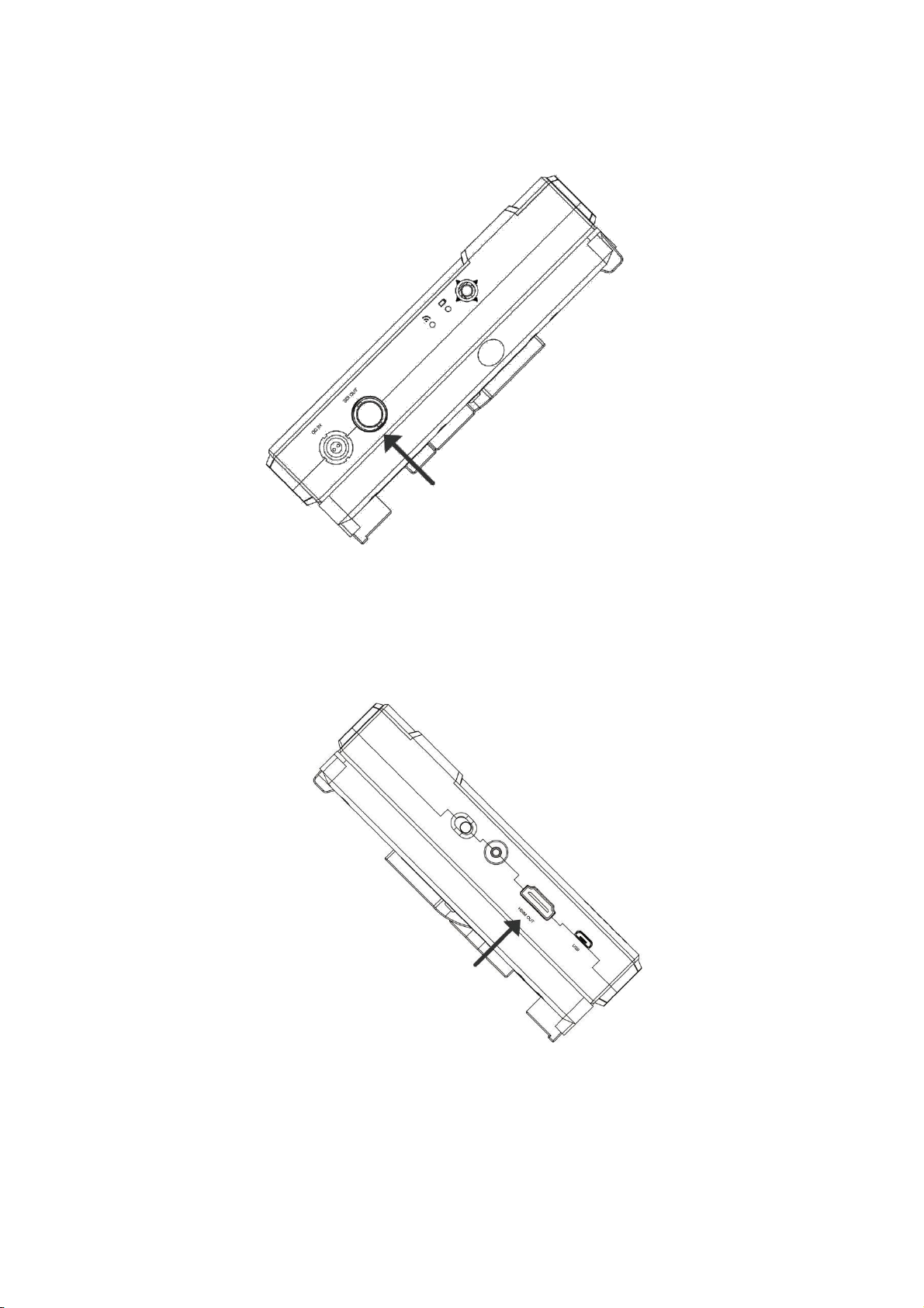
This section describes how to set up the Thor 800FT+ receiver. You may set up the receiver using
SDI, HDMI, or both. We highly recommend that the accessories and cables you use are of the
highest quality.
IMPORTANT! For optimal system performance, carefully read and then implement the guidelines
listed in Placement Recommendations for transmitter and receiver.
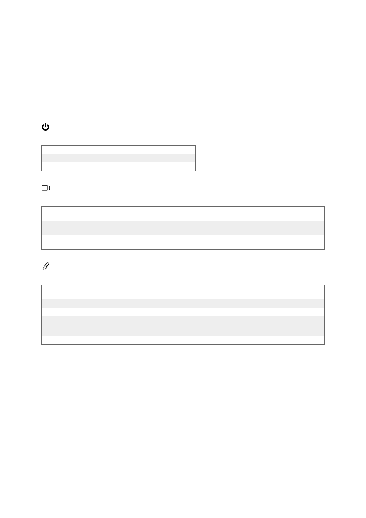
To set up the Thor 800FT+ Receiver:
1. Screw on the 3 provided antennas to the receiver’ 3 connectors , as shown below:

7

8
2. Enable display of the received video via SDI by connecting a standard SDI cable from the
Receiver's SDI port to the monitor's SDI port.
3. Enable display of the received video via HDMI by connecting a standard HDMI cable from
the Receiver's HDMI port to the monitor’s HDMI port.

9
4. Connect the power cable to the Lemo connector on the Receiver, and connect the other end
to a power source.
5. Verify that both LEDs on the Receiver light up, as described in the tables below.
LED Behavior
The Thor 800FT+ Receiver features two LED indicators: a Video LED and a Signal LED. In
normal operating conditions, both LEDs show a constant green color. No power (or low power) is
indicated by the LEDs turning off.
When the indicators in both LEDs are blinking quickly, a system error has been detected. In this
case, contact VAXIS support.
The behaviors of each individual LED are described in the tables below.
Receiver – Video LED
Solid The video signal from the camera is locked (i.e., the signal is being received from the Transmitter.)
Blinks Slowly The video signal from the camera is not locked.
Blinks Quickly The camera is transmitting a video resolution that is not supported. For a list of supported resolutions.
Receiver – Signal LED
Solid A link has been established to the Receiver.
Blinks Quickly Registration is in progress, or the Receiver has gone out of range.
Blinks Slowly The Transmitter is establishing a link with the Receiver.

10
4. Placement Guidelines and Best Practices
■Maintaining Line of Sight (LOS)
In order to obtain maximal range from the Vaxis Thor 800FT+, it is necessary to maintain proper
line of sight (LOS) between the Transmitter and the Receiver. Adhere to the following
recommendations to achieve best LOS:
• To ensure optimal RF conditions, place both the Transmitter and the Receiver as high as
possible.
• Remember that any obstacle between the Transmitter and the Receiver might reduce range.
Avoid positioning your units in places where there is object interference (e.g., a wall).
• If placement in the vicinity of an obstacle cannot be avoided, keep in mind that different types of
ob-stacles have different effects on the range. For example, a brick wall will cause more
interference that a thin drywall.
For more placement guidelines and best practices, refer to Placement Recommendations for
Transmitter and Receiver .
■Placement Recommendations for Camera and Monitor Units
In order to obtain maximal performance from the StudioLink system, always adhere to the
following placement recommendations:
• Ensure proper line of sight (LOS) between the Transmitter and the Receiver. For details,
refer to Maintaining Line of Sight (LOS).
• To achieve maximal range, position all antennas in an upright position.
• Avoid or remove any interfering obstacles, especially metal parts (such as the body of the
camera).
• Maintain a distance of one meter between Transmitters.
• Maintain a distance of at least one meter between Receivers.
• Mount the Receivers on tripods at a height of 1.5 meters.
The following figure shows an example of proper placement of the Transmitter and the Receiver:

11
5. Vaxis Thor 800FT+ Operational Instructions
■Working with On Screen Display (OSD) Functions
When OSD functionality is enabled, you can view additional data displayed on the monitor
attached to the Receiver, and monitor system parameters from the OSD menus. The following
data is overlaid on the video received from the Camera Unit:
• Basic system parameters, such as current link quality and video resolution. For details, refer to
Acti-vating the Information Bar.
• Various alerts and notifications. For more information, refer to Alert and System Messages.
You can perform the following activities from the OSD menus:
• Check data related to the Thor 800FT+ you are working with (e.g., firmware version). For
details, refer to Viewing Paired Unit Parameters.
• Pair additional Monitor Units with the Camera Unit. For more information, refer to Multicasting to
Mul-tiple Receivers.
Activate and manipulate the On Screen Display features using the OSD joystick on the Monitor
Unit. For more details on operating the joystick, refer to Using the OSD Joystick.

12
Using the OSD Joystick
The OSD joystick is made up of four direction selectors (Up, Down, Left and Right) and a
confirmation button in the center. Enable On Screen Display by pressing the confirmation button.
The Main Menu screen is displayed on the monitor.

13
Navigate through the menus using the direction selectors:
•Down: Goes to the next menu or the next menu option.
•Up: Goes to the previous menu or the previous menu option.
•Right: Enters the options list of the currently selected menu.
•Left: Exits the options list of the currently selected menu.
Activating the Information Bar
The Info Bars menu option determines whether or not the Information Bar is overlaid on the video
received from the Transmitter. Toggle the option between <OFF> and <ON> by pressing the Right
direction selector on the OSD joystick.
When the Info Bars option is <ON>, the following information is displayed in the Information Bar:
Icon Description
Transmitter to Receiver video signal strength.
Distance of the Transmitter from the Receivert (in meters).
Video resolution captured by the camera.
For example:

14
Viewing Unit Parameters
The Status menu lists information related to the Transmitter and Receiver you are working with.
The following parameters are displayed:
•Paired Tx: The name of the Transmitter with which the Receiver is paired.
•SN: Serial number of the paired Transmitter .
•Rx FW Ver: Firmware version of the Receiver.
•Tx FW Ver: Firmware version of the Transmitter.
IMPORTANT
For the system to perform as expected, the firmware version in the Receiver and
the Transmitter must be the same.
Alert and System Messages
The tables below describe messages that may appear on the monitor connected to the
Receiver's SDI or HDMI port.
Alert Messages – Overlaid on Video During Link
These alert messages may be displayed on top of the live video:
Alert
Description
Out of Range
A link still exists, but Transmitter is too far from the Receiver. This message appears regardless of
whether OSD display is enabled.
When the Transmitter is within range, the video signal is automatically reacquired.

15
Approached
This alert is displayed for 30 seconds, from the moment the Transmitter has been detected as out of range
Range Limit
until the Out of Range warning is displayed. The message is a warning that the video signal is about to be
lost.
This message appears only when OSD display is enabled.
Video Signal Not
A link has been established between the Transmitter and the Receiver, but no video signal has been
Detected
detected. This message appears regardless of whether OSD display is enabled.
System Messages – No Link
These system messages may appear when no live video is displayed:
Alert
Description
Searching for
This message is displayed until a link is established. This may occur when the Transmitter is out of range
Transmitter
or unavailable, or when the Receiver has been removed from its list of paired devices.
Pairing in Progress
This message is displayed while the Transmitter is pairing with a Receiver.
For a detailed description of the pairing process, refer to Multicasting to Multiple Monitor Units.
Multicasting to Multiple Receivers
A single Transmitter can transmit video downlink to up to 4 Receivers. This is called multicasting. The
following procedure describes how to pair an additional Receiver with the same Transmitter.
NOTE
1. The Transmitter and Receiver provided in the same box are preconfigured to
au-tomatically search for and connect to each other. Therefore, there is no
need to perform this procedure on the Transmitter / Receiver delivered in the
same box.
2. Register one Receiver at a time to each Transmitter.
Pairing Additional Receivers with a Transmitter
To pair an additional Receiver with a Transmitter:
1. Set up the additional Receiver, as described in Setting Up the Thor 800FT+ Receiver. The
Receiver must be placed between one and ten meters from the Transmitter. To enable optimal
reception, each Receiver must be placed at least a few meters away from other Receivers.
After setting up the additional Receiver, the following message is displayed on the monitor
connected to the Receiver’s SDI or HDMI port:
"Receiver not registered to Transmitter."
2. From the Receiver, activate the OSD display. Navigate to the Pairing menu, and select
Start Pairing.

16
NOTE
For more information about using the OSD joystick, refer to Working with
OSD Functions.
The Signal LED starts blinking, and the following message is displayed on the monitor
connected to the Receiver:
"Please activate registration on Transmitter."
3. Power on the Transmitter with which to pair this Receiver. It is assumed that the Transmitter
has already been set up, as described in Setting Up the Thor 800FT+ Transmitter].
4. Press and hold the Transmitter’s Reg button for approximately five seconds, until the
Signal LED starts blinking.
The following message is then displayed on the monitor connected to the Receiver:
"Pairing in progress."
After a while, the monitor connected to the Receiver should display the video received from
the Transmitter.

17
6. Maintenance
■Storage conditions
Products storage temperature should be -20°C~60°C. For long time
storage requirement, please use original carbon boxes, and avoid from
high humid, acid base or dusty place.
■Maintenance
Warning
To ensure your safety, place choose well-known brand DC batteries, and
guarantee suitable work conditions that battery manual mentioned.

Table of contents
Other VAXIS Microphone System manuals