manuals.online logo
Brands
  1. Home
  2. •
  3. Brands
  4. •
  5. Chiayo
  6. •
  7. Microphone System
  8. •
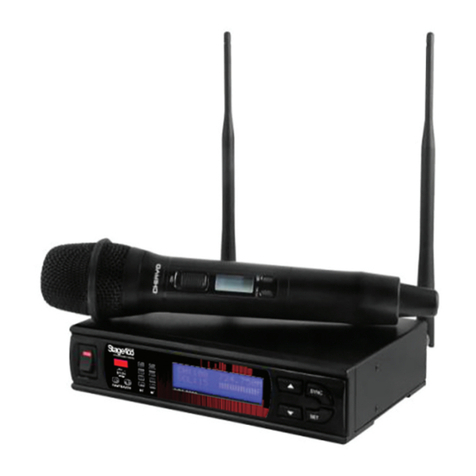
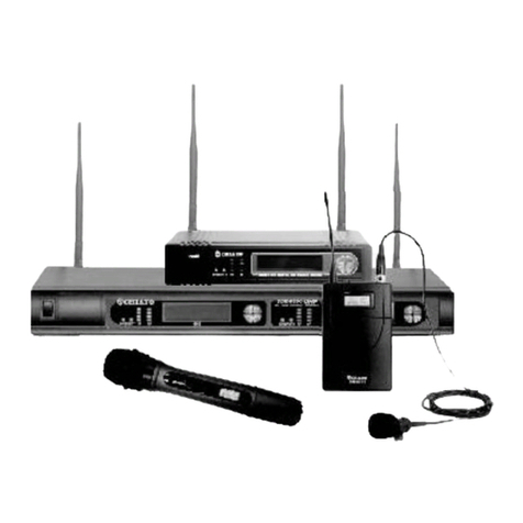
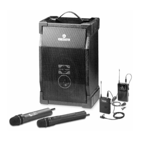
  9. Chiayo RRS-2000 User manual

Chiayo RRS-2000 User manual

RRS-2000
RCC-2000
eXtra Long Range (XLR) Wireless Microphone System
ISO 9001
ISO
140 0 1
REGIS T E R ED
ISO 14001
O H S A S
180 0 1
REGIS T E R ED
OHSAS 18001
GREEN PRODUCT
Operation manual
-1-
Thank you and congratulation for purchasing CHIAYO’s professional XLR (eXtra Long Range)
cellular concept multi-diversity reception wireless microphone system. Please read this manual
thoroughly to familiarize with the function of each part before use.
Basic Concept
This system consists of two main parts:
1. Remote Control Center RCC-2000
2. Remote Receiver Station RRS-2000
The Remote Control Center RCC-2000 is the nerve center of the whole system. It is capable of
controlling up to 4 units of Remote Receiver Station RRS-2000, delivering power supply and
receiving / monitoring signal of the individual Remote Receiver via Cat 5e cable.
Each Remote Receiver Station RRS-2000 has an antenna divider plus power distribution and is
capable of holding 2 diversity receiver modules RR-2000M (CH A and CH B). An optional
outdoor waterproof mounting kit PRR-2000 is available for outdoor installation.
Various Installation Scenarios:
Parts and functions of RCC-2000
RCC-2000 Front Panel
12 3 45
6
7
8
1. Power switch.
2. CH A CH B RF signal indicator of the 2 remote receivers.
3. CH A CH B AF signal indicator of the 2 remote receivers.
4. LCD display
5. UP button
6. DOWN button
7. MENU button
8. SET button
ISO 9001 / ISO 14001 / OHSAS 18001
-2-
RCC-2000 Rear Panel
1
234
5
6
7
8
9
1. DC-input
2. Remote Receiver Station RRS connector (RJ-45 jack for CAT.5e)
3. Remote Receiver Station RRS connector (RJ-45 jack for CAT.5e)
4. Remote Receiver Station RRS connector (RJ-45 jack for CAT.5e)
5. Remote Receiver Station RRS connector (RJ-45 jack for CAT.5e)
6. Channel B balanced audio output (XLR)
7. Channel B unbalanced audio output (Ø 6.3mm)
8. Channel A balanced audio output (XLR)
9. Channel A unbalanced audio output (Ø 6.3mm)
Various settings on the remote control center RCC-2000
Adjusting the volume
Press MENU button to go to , then hold SET to enter setting.
Choose A or B by SET button, and UP/DOWN buttons to adjust the volume. The setting will be
automatically saved after five seconds.
Warning: In order for this function to work correctly, the volume of the remote receiver module
side should be manually fixed at an appropriate level beforehand!
Changing ON/OFF status of the remote stations
Press MENU button to go to , then hold SET to enter setting.
Choose A or B by SET button, and UP/DOWN buttons to switch ON/OFF status of individual
Remote Station R1,R2,R3 and R4. The setting will be automatically saved after five seconds
and shown at the individual.
Warning: This function is only possible when the remote receiver module is switched ON
beforehand!.
-3-
Changing the frequency
Press MENU button to go to , then hold SET to enter setting.
Choose A or B by SET button, and UP/DOWN buttons to change the frequency. The setting will
be automatically saved after five seconds and will be sent to and shown at all the connected
RR-2000M's 2-digit 7-segment LED display. CH A will be 01 and CH B will be 00 (for 100)
The display value indicates the RF signal strength.
Pointer ””indicates which RRS-2000’s module the audio comes
from. The item marked with “x” is power off on either the module itself or RCC-2000.
ISO 9001 / ISO 14001 / OHSAS 18001
-4-
Parts and functions of Remote Receiver Station RRS-2000 and RR-2000M
Each Remote Receiver Station RRS-2000 can hold up to 2 pieces of RR-2000M receiver modules!
RRS-2000 Front Panel
CH A CH B
12
3 4 5 6 7
RR-2000M RR-2000M
1. 7-segment LED display
2. Channel UP button
3. Channel DOWN button (RCC has priority and overrides this button for CH #)
4. AF signal indicator
5. RF signal indicator
6. Module power/volume control
Channel Name setting on the remote receiver RR-2000M
Each Remote Station RRS-2000 can hold up to 2 units of RR-2000M receiver modules. A
channel (CH A) is assigned on the left and B channel (CH B) assigned on the right of this rack.
If this unit is connected to the Remote Station's RS1of the RCC-2000, module A must be set to
A1 and module B to B1. If another RRS-2000 is connected to the RS2 RJ-45 connector, its
module A must be set to A2 and module B set to B2. And so on.
To do the setting, first hold both UP and DOWN buttons till the LED flashes. Then press UP
button to select A or B and DOWN button to select 1/2/3/4.
Precisely, the two receivers of 1st Station should be named as A1 and B1, for 2nd station A2
and B2, for 3rd Station A3 and B3, for 4th Station A4 and B4. This should be done so in
accordance with the preset programming in the Remote Control Center RCC-2000.
(RCC has priority and overrides this button for CH #)
After name setting, the LED will return back to the allocated channel number programmed at
the RCC-2000.
-5-
RRS-2000 Rear Panel
123
1. Antenna B (TNC)
2. RJ-45 jack CAT.5e cable.
3. Antenna A (TNC)
Rack Mounting for RCC-2000
RCC-2000 has a half-19"-casing design. It can be cabinet-mounted with either one or two units.
Individual kits for mounting one or two units are available and please refer to following
assembly illustration.
ISO 9001 / ISO 14001 / OHSAS 18001
-6-
Outdoor weatherproof mounting of Remote Receiver Station RRS-2000
Remote Station can be mounted outdoor in a weatherproof casing PRR-2000 as follow:
-7-
UHF handheld microphones(SQ-SQ-6100/SQ-7100)
Parts and functions
1 2 3 4 5 6 91011
7 8
Microphone parts and functions
SQ-6100
SQ-7100
Cartridge
1
1
Battery weak/power LED
2
2
Power switch
3
7
LCD
4
4
Battery compartment
5
5
Bottom cap
6
6
Locking button
7
-
Audio mute switch
-
3
Setting button
8
8
Up button
9
9
Down button
11
11
Charging port
10
10
Battery installation
Insert or replace the batteries according to the correct polarity after opening the compartment.
Many batteries are known to have leakage problem of conductive and corrosive liquid. So
please remove the batteries if they are not to be used for a long period.
Other settings
1. Channel setting
Use UP or DOWN button to go to the CHANNEL/ FREQUENCY page.
The cursor will flash to allow changes to be made. Pressing UP or DOWN button will increase
or decrease the channel number. The corresponding frequency will change accordingly. When
a desired channel is selected, it will be automatically saved and stored in the memory.
2. Making changes to Battery selection
Use UP or DOWN button to go to the Battery selection page.
Press UP or DOWN button to move the cursor to either NiMH (rechargeable battery) or AKLN
(Alkaline battery) position.
When the desired battery has been selected, it will be automatically saved and stored in the
memory.
ISO 9001 / ISO 14001 / OHSAS 18001
-8-
Remark: NiMH battery must be selected when rechargeable battery is being used. Never
select AKLN (Alkaline) when microphone is intended for charging as Alkaline battery can’t be
charged. Wrong selection of battery will result in battery sensing electronics to display wrong
and misleading status information.
3. Making changes to Sensitivity Level
Use UP or DOWN button to go to the SENS SET page.
Press UP or DOWN button to increase or decrease the Sensitivity Level of the microphone.
The MAX level is 4 and the MIN level is 1.When a desired sensitivity level has been selected
for your application, it will be automatically saved and stored in the Memory.
Remark: When selecting Sensitivity level, please bear in mind that Level 1 is for close
proximity singing purposes whereas Level 4 is for use of microphone on tripod mount for
speech purposes. When Level 4 setting is used for close proximity singing, high SPL input will
result in undesirable distortion in the output.
After performing setting changes, you could turn the protective cover 180°in either direction to
block the buttons from being accidentally adjusted.
-9-
UHF belt-pack transmitters(SM-7100)
Parts and functions
1
234
6
5
7
8
12
9
11
10
13
14
15 15
Transmitter parts and functions
SM-7100
Antenna
1
Battery weak/audio mute indicator
2
Audio mute switch
3
(Lavalier microphone) Mini XLR connector
4
LCD
5
Charging port
6
Cover release button
7
Power switch
8
Gain control (GT, high impedance)
9
Gain control (MT, low impedance)
10
Setting button
11
Up button
12
Down button
13
Battery compartment
14
Charging contacts
15
ISO 9001 / ISO 14001 / OHSAS 18001
-10-
Battery installation
Insert or replace the batteries according to the correct polarity after opening the compartment.
Many batteries are known to have leakage problem of conductive and corrosive liquid. So
please remove the batteries if they are not to be used for a long period.
Other settings
1. Channel setting
Use UP or DOWN button to go to the CHANNEL/ FREQUENCY page.
The cursor will flash to allow changes to be made. Pressing UP or DOWN button will increase
or decrease the channel number. The corresponding frequency will change accordingly. When
a desired channel is selected, it will be automatically saved and stored in the memory.
2. Making changes to Battery selection
Use UP or DOWN button to go to the Battery selection page.
Press UP or DOWN button to move the cursor to either NiMH (rechargeable battery) or AKLN
(Alkaline battery) position.
When the desired battery has been selected, it will be automatically saved and stored in the
memory.
Remark: NiMH battery must be selected when rechargeable battery is being used. Never
select AKLN (Alkaline) when microphone is intended for charging as Alkaline battery can’t be
charged. Wrong selection of battery will result in battery sensing electronics to display wrong
and misleading status information.
CHIAYO ELECTRONICS CO.,LTD.
Http://www.chiayo.com.tw Email: [email protected]
Office: 30, Lane 27, Section 4, Jen-Ai Road, Taipei 10685, Taiwan / Tel: 886-2-27415741 / Fax: 886-2-27525242
Factory: 88, Chung-Hsiao Street 2, Chiayi 60080, Taiwan / Tel: 886-5-2711000 / Fax: 886-5-5767611
12I1287

This manual suits for next models

1

Other Chiayo Microphone System manuals
Chiayo QR-4000 U User manual

Chiayo

Chiayo QR-4000 U User manual

Chiayo R-1001 User manual

Chiayo

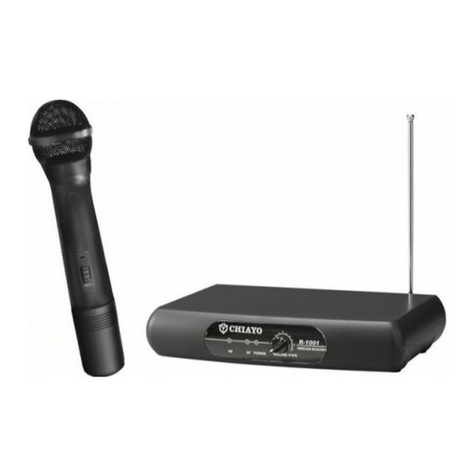
Chiayo R-1001 User manual

Chiayo RR-2000 User manual

Chiayo

Chiayo RR-2000 User manual

Chiayo DH2400 User manual

Chiayo

Chiayo DH2400 User manual

Chiayo Live-100 series User manual

Chiayo

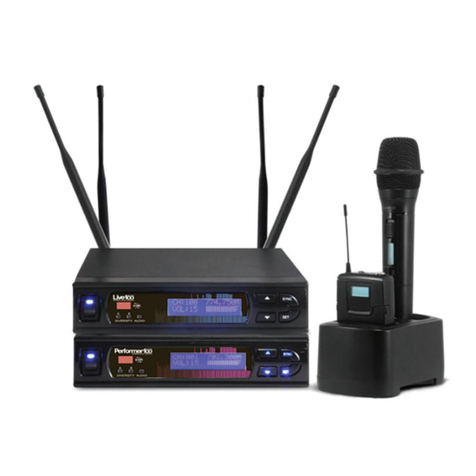
Chiayo Live-100 series User manual

Chiayo COACH PRO User manual

Chiayo

Chiayo COACH PRO User manual

Chiayo QR-2000N User manual

Chiayo

Chiayo QR-2000N User manual

Chiayo UDR-500 User manual

Chiayo

Chiayo UDR-500 User manual

Chiayo IWR-320 User manual

Chiayo

Chiayo IWR-320 User manual

Chiayo R-1010 User manual

Chiayo

Chiayo R-1010 User manual

Chiayo SDR-8200 User manual

Chiayo

Chiayo SDR-8200 User manual

Chiayo AIR-812 User manual

Chiayo

Chiayo AIR-812 User manual

Chiayo SDR-5100 IrDA User manual

Chiayo

Chiayo SDR-5100 IrDA User manual

Chiayo DWR-5420 User manual

Chiayo

Chiayo DWR-5420 User manual

Chiayo IRX2 User manual

Chiayo

Chiayo IRX2 User manual

Chiayo Q-818 User manual

Chiayo

Chiayo Q-818 User manual

Chiayo IRX2 User manual

Chiayo

Chiayo IRX2 User manual

Chiayo SDR-5216 User manual

Chiayo

Chiayo SDR-5216 User manual

Chiayo IWR-200 User manual

Chiayo

Chiayo IWR-200 User manual

Chiayo Stage-100 Series User manual

Chiayo

Chiayo Stage-100 Series User manual

Chiayo IWM-202 User manual

Chiayo

Chiayo IWM-202 User manual

Chiayo NDR-3100 User manual

Chiayo

Chiayo NDR-3100 User manual

Chiayo SDR-6200 IrDA User manual

Chiayo

Chiayo SDR-6200 IrDA User manual
Chiayo Artist User manual

Chiayo

Chiayo Artist User manual

Popular Microphone System manuals by other brands

WisyCom CSI16T user manual

WisyCom

WisyCom CSI16T user manual

Saramonic UwMic9 user manual

Saramonic

Saramonic UwMic9 user manual

Audio Technica Artist Elite 4000 Series Installation and operation guide

Audio Technica

Audio Technica Artist Elite 4000 Series Installation and operation guide

JBL WEM-1 owner's guide

JBL

JBL WEM-1 owner's guide

Paso NA153 Instructions for use

Paso

Paso NA153 Instructions for use

FUTAIHUA CMC187 user manual

FUTAIHUA

FUTAIHUA CMC187 user manual

auna PRO UHF-550 Quartett manual

auna PRO

auna PRO UHF-550 Quartett manual

Shure 404B datasheet

Shure

Shure 404B datasheet

Shure KCX Quick setup

Shure

Shure KCX Quick setup

Party Light & Sound WM-USB instruction manual

Party Light & Sound

Party Light & Sound WM-USB instruction manual

Chord 171.924UK user manual

Chord

Chord 171.924UK user manual

DAPAudio EB-16 manual

DAPAudio

DAPAudio EB-16 manual

Power Dynamics 179.120 instruction manual

Power Dynamics

Power Dynamics 179.120 instruction manual

Karma SET 7440 instruction manual

Karma

Karma SET 7440 instruction manual

Pyle Pro PDWM4650 user manual

Pyle Pro

Pyle Pro PDWM4650 user manual

Lexicon-Global VPT100 Setup guide

Lexicon-Global

Lexicon-Global VPT100 Setup guide

Redback C 8884 operating instructions

Redback

Redback C 8884 operating instructions

Sennheiser EMP 2015 instruction manual

Sennheiser

Sennheiser EMP 2015 instruction manual

manuals.online logo
manuals.online logoBrands
  • About & Mission
  • Contact us
  • Privacy Policy
  • Terms and Conditions

Copyright 2025 Manuals.Online. All Rights Reserved.