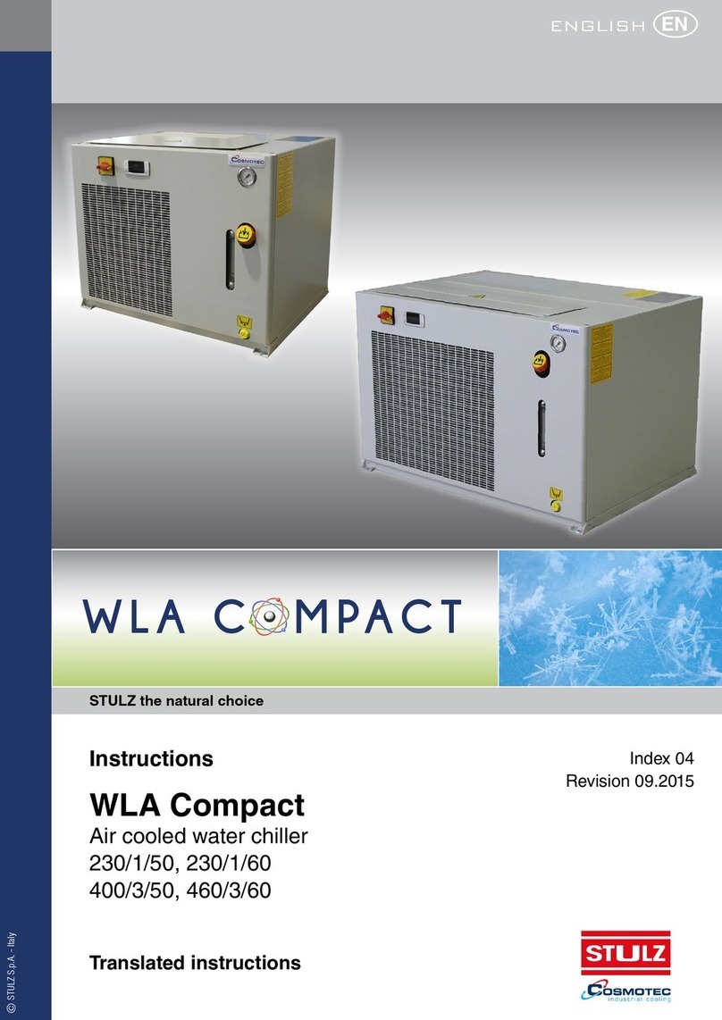
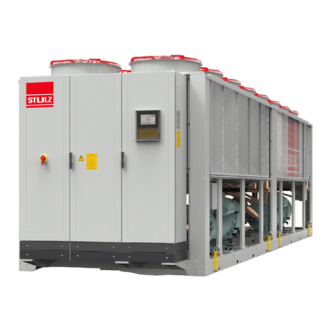
Stulz WSA Explorer Series User manual

Index i09
Issue 06.2016
WSA Explorer
Original instructions
Water cooled liquid chillers
400V / ~3 / 50Hz

2EN/06.2016/i09 © STULZ S.p.A. – all rights reserved
WSA EXPLORER ORIGINAL INSTRUCTIONS
ABOUT STULZ
Customer focus, entrepreneurial spirit and technological
expertise – these have formed the basis for the
successful growth of STULZ.
In 1971 we began specializing in the development
and production of precision air conditioning units and
chillers. That's a wealth of experience gathered over 40
years and from many thousands of projects that we have
implemented worldwide. We have systems and solutions
of all sizes and with the most diverse requirements -
take advantage of our know-how.
Founded in Hamburg in 1947, today STULZ has a
presence in over 140 countries. The STULZ Group
has STULZ subsidiaries in 17 countries, 7 production
plants in Europe, the USA, India and 2 in China and
more than 140 exclusive sales and service partners on
all continents. The family-owned company employs a
workforce of over 5,300 all over the world.
STULZ S.p.A.
via Torricelli, 3
37067 Valeggio Sul Mincio
Verona - Italy

3© STULZ S.p.A. – all rights reserved EN/06.2016/i09
WSA EXPLORER ORIGINAL INSTRUCTIONS
WSA Explorer – High quality liquid
chiller made in Italy
Dear Customer,
Thank you for purchasing a STULZ chiller.
It is the result of many years of research and design studies, as well as a fine matching of
materials and technologies to obtain a high quality chiller.
The CE mark guarantees that the STULZ products fulfill the requirements of the European
Machinery Directive for safety.
The level of quality is permanently checked at every phase, from design to production and makes
STULZ products synonymous of SAFETY, QUALITY and RELIABILITY.
For any questions or requests concerning products by STULZ SpA, please contact our
Aftersales at
telephone 0039 045 6331615
fax 0039 045 6331635
email aftersales@stulz.it
Or visit our website for more information about our products and services:
www.stulz.it

4EN/06.2016/i09 © STULZ S.p.A. – all rights reserved
WSA EXPLORER ORIGINAL INSTRUCTIONS
Table of Contents
1. Introduction ...........................................................................................6
1.1 Introduction .............................................................................................................................................. 6
1.2 Warranty...................................................................................................................................................... 6
1.3 Safety ............................................................................................................................................................ 7
1.3.1 Symbols used in the manual.................................................................................................................................. 7
1.3.2 Labels.................................................................................................................................................................................... 7
1.3.3 Safety Instructions....................................................................................................................................................... 9
1.3.4 Handling refrigerants................................................................................................................................................. 9
1.3.5 Safety and environmental requirement....................................................................................................... 10
2. Residual risk ........................................................................................12
2.1 Transport and installation.............................................................................................................12
2.2 Start-up....................................................................................................................................................12
2.3 Operation................................................................................................................................................12
2.4 Maintenance.........................................................................................................................................13
2.5 Dismantling............................................................................................................................................13
2.6 Safety Data............................................................................................................................................13
3. Transport/ Storage...............................................................................15
3.1 Delivery of units..................................................................................................................................15
3.2 Storage.....................................................................................................................................................16
3.3 Transport ................................................................................................................................................. 16
3.3.1 Transport protection ...............................................................................................................................................16
3.3.2 Centre of gravity......................................................................................................................................................... 20
4. Description ..........................................................................................22
4.1 Type Code ..............................................................................................................................................22
4.2 Intended use.........................................................................................................................................23
4.3 Chiller Design.......................................................................................................................................23
4.3.1 General............................................................................................................................................................................. 23
4.3.2 Versions............................................................................................................................................................................ 23
4.3.3 Refrigerant Circuit.....................................................................................................................................................23
4.3.4 Compressor...................................................................................................................................................................24
4.3.5 Evaporator......................................................................................................................................................................24
4.3.6 Condenser...................................................................................................................................................................... 24
4.3.7 Electrical Cabinet....................................................................................................................................................... 24
4.3.8 Sensors ............................................................................................................................................................................24
4.3.9 C2020 ..............................................................................................................................................................................25
4.4 Piping diagrams..................................................................................................................................25
4.4.1 Legend .............................................................................................................................................................................26
4.5 Hydraulic diagrams...........................................................................................................................31
4.5.1 Legend .............................................................................................................................................................................31
5. Technical Data .....................................................................................35
5.1 Application limits ..............................................................................................................................35
5.1.1 Storage conditions .................................................................................................................................................. 35
5.1.2 Operating conditions............................................................................................................................................... 35
5.2 Chilled water quality .........................................................................................................................37
5.2.1 Glycol correction factors........................................................................................................................................37
5.3 Pressure Drops....................................................................................................................................38
5.4 Head pressure available ...............................................................................................................39
5.5 Technical Data .....................................................................................................................................41
5.6 Dimensional drawings ....................................................................................................................52

5© STULZ S.p.A. – all rights reserved EN/06.2016/i09
WSA EXPLORER ORIGINAL INSTRUCTIONS
Subjet to change without notice
5.7 Electrical connection data............................................................................................................ 56
6. Installation ...........................................................................................57
6.1 Positioning ..............................................................................................................................................57
6.1.1 Minimum distance from obstacles or other chillers............................................................................ 58
6.1.2 Distance of installation of several units......................................................................................................58
6.2 Weight on the supports.................................................................................................................59
6.3 Refrigerant circuit..............................................................................................................................62
6.4 External water circuit ......................................................................................................................62
6.5 Water connection .............................................................................................................................. 64
6.6 Filling and bleeding air ..................................................................................................................65
6.7 Electrical connection .......................................................................................................................66
6.8 Opening the electric cabinet .....................................................................................................66
6.9 Position of the electrical connections ..................................................................................67
6.10 Pump control..................................................................................................................................... 68
6.10.1 System with external pump ............................................................................................................................. 68
7. Commissioning ....................................................................................69
7.1 Preparation.............................................................................................................................................69
7.2 First Startup ........................................................................................................................................... 69
7.2.1 Oil pre-heating ..............................................................................................................................................................70
7.2.2 Commissioning of the chilled water circuit ................................................................................................70
7.2.3 Commissioning of the refrigerant circuit .....................................................................................................71
8. Maintenance ........................................................................................73
8.1 Safety instructions.............................................................................................................................73
8.1.1 Warning notes...............................................................................................................................................................73
8.2 Maintenance intervals .....................................................................................................................73
8.3 Refrigerant Circuit..............................................................................................................................74
8.3.1 Refrigerant charge.....................................................................................................................................................74
8.3.2 Quantity.............................................................................................................................................................................75
8.3.3 Tightness of refrigerant circuit...........................................................................................................................75
8.3.4 Purity...................................................................................................................................................................................75
8.3.5 Exchange of filter drier...........................................................................................................................................75
8.3.6 HP switch.........................................................................................................................................................................76
8.3.7 LP switch...........................................................................................................................................................................76
8.3.8 Expansion valve............................................................................................................................................................77
8.3.9 Compressor.....................................................................................................................................................................77
8.4 Air circuit ..................................................................................................................................................79
8.4.1 Condenser.......................................................................................................................................................................79
8.4.2 Condenser Fan.............................................................................................................................................................79
8.4.3 Filter ....................................................................................................................................................................................79
8.5 Evaporator circuit................................................................................................................................79
8.5.1 Tightness.........................................................................................................................................................................80
8.5.2 Evaporator......................................................................................................................................................................80
8.5.3 Differential pressure switch ................................................................................................................................ 80
8.6 Electric circuit ...................................................................................................................................... 80
8.6.1 Powerboard ...................................................................................................................................................................80
8.7 Unit in general......................................................................................................................................80
9. Malfunction..........................................................................................82
10. Dismantling and disposal.....................................................................84
11. CE declaration of Conformity ...............................................................85
12. Options ................................................................................................86

6EN/06.2016/i09 © STULZ S.p.A. – all rights reserved
WSA EXPLORER ORIGINAL INSTRUCTIONS
1. Introduction
1.1 Introduction
These operating instructions contain basic information which is to be complied with for instal-
lation, operation and maintenance. They must therefore be read and complied with by the fitter
and the responsible trained staff/operators before assembly and commissioning. All procedures
detailed in the manual, including tasks for installation, commissioning and maintenance must
only be performed by suitable trained and qualified personnel. They must be permanently avail-
able at the place where the system is used.
The manufacturer will not be liable for any injury or damage caused by incorrect installation,
commissioning, operation or maintenance resulting from a failure to follow the procedures and
instructions detailed in the manual.
1.2 Warranty
The warranty is limited to free replacement and shipping of any faulty part, or sub-assembly
which has failed due to poor quality or manufacturing errors. All claims must be supported by
evidence that the failure has occurred within the warranty period, and that the chiller has been
operated within the designed parameters specified.
All warranty claims must specify the model and serial number of the chiller. This information is
printed on the name plate, fitted on the door from the electrical cabinet.
The warranty will be invalid in case of any modification on the chiller which is not written
approved from STULZ.
To claim any warranty purpose the following conditions need to be satisfied:
The initial startup of the chiller has to be carried out by trained personnel authorized from
STULZ.
Only STULZ approved spare parts and liquids are allowed to be used.
All scheduled maintenance operations described in this manual must be performed accordingly
by trained and qualified personnel.
Not fulfilling at least one these conditions will automatically void the warranty.

7© STULZ S.p.A. – all rights reserved EN/06.2016/i09
WSA EXPLORER ORIGINAL INSTRUCTIONS
1.3 Safety
1.3.1 Symbols used in the manual
DANGER Risk of death or injury to the operator
WARNING Risk of damage to the unit
INFORMATION Important information, use note
ESD CAUTION Risk of damage to electronic components
1.3.2 Labels
Label recalling the instruction manual.
Location: on the side of the powerboard.
Entrance of the hydraulic circuit of
the chiller (intet of the chiller).
Location: next to the inlet fitting of
the hydraulic circuit.
Exit of the hydraulic circuit of the
chiller (outlet of the chiller).
Location: next to the outlet fitting
of the hydraulic circuit.
Evaporator drain.
Location: next to the taps to empty
the evaporators.
Hot surface.
Location: in the proximity of the input / output pipes of condensers (under the
protective casing) and on the compressors. With equipped antifreeze option,
even in the proximity of the heaters around the evaporator and the steel
hydraulic piping.

400/3/50 V
45 bar
85 °C
239/150,5 A
195 kW (W15L35)
45 °C
C1=16,5 - C2=16,5 kg
R410A
1900 kg
Tensione nominale - Rated voltage -
Nennspannung - Tension nominale
PS HP (Max pressione ammissibile HP - Max allowable pressure
HP - Max zulässiger Druck HP - Pression maximum admise HP)
TS MAX (Refrigerante - Refrigerant - Kaltemittel - Refrigerant)
Avviamento/marcia - Starting/run current -
Anlaufstrom/Nennstrom - Démarrage/marche
Resa nom. - Cooling cap. - Kalteleistung -
Puissance nominale
Potenza Assorbita - Input power - Leistungsaufnahme -
Puissance absorbée
TSS (Max temp. Di stoccaggio - Max Storage temp. - Max
Lagertemperatur - Temp. Max d'emmagasinage)
Carica gas - Filling capacity - Fullmenge - Charge de gaz
Refrigerante tipo - Refrigerant type - Kaltemittel - Refrigerant type
Peso - Weight - Gewicht - Poids
89,6 kW (W25L45)
Contiene gas fluorurati ad effetto serra disciplinati dal protocollo di Kyoto - Device
containing HFC fluids causing greenhouse effect regulated by Kyoto protocol - Das Gerät
erhält wie vom Kyoto-Protokoll geregelte Fluorkohlenwasserstoffe Treibhausgasen -
Dispositif contenant fluides HFC à effet de serre disciplinés par le protocole de Kyoto
REFRIGERATORE DI LIQUIDO - LIQUID COOLER -
KUHLANLAGE - REFROIDISSEUR DE LIQUIDE
SERIE - SERIES - SERIE - SERIE
DATA - DATE - DATUM - DATE
WPAR044207ZFT0 7035
N°0000408788
07/11/12
MODELLO - MODEL - TYP - MODELE
MADE IN ITALY
ORDINE - ORDER - ORDER - COMMANDER
2120002673
- 1 0 °C
TS MIN (Refrigerante - Refrigerant - Kaltemittel - Refrigerant)
26 bar
PS LP (Max pressione ammissibile LP - Max allowable pressure
LP - Max zulässiger Druck LP - Pression maximum admise LP)
II
CAT PED
Modulo valutazione - Evaluation Module - Bewertungsverfahren -
Procédure d'évaluation
A1
0035
8EN/06.2016/i09 © STULZ S.p.A. – all rights reserved
WSA EXPLORER ORIGINAL INSTRUCTIONS
Discharge of the safety valves of the chiller.
Location: in the proximity of the refrigerant discharges of the safety valves.
The chiller is identified by the nameplate shown on the left.
The identification nameplate also shows the serial number of
the unit, it is important to know the label as it is essential to get
assistance or any information concerning the unit described in
this manual.
Location: on the side of the powerboard.
Lifting point.
Location: near the lifting points on the base frame of the unit.
Ground point.
Location: on the structure, close to properly designed holes.

9© STULZ S.p.A. – all rights reserved EN/06.2016/i09
WSA EXPLORER ORIGINAL INSTRUCTIONS
1.3.3 Safety Instructions
INFORMATION
This cooling unit contains fluorinated greenhouse gas covered by the Kyoto protocol
In these STULZ chillers the refrigerant R134a is used. Refrigerants are volatile or highly volatile
fluorinated hydrocarbons which are liquefied under pressure. They are incombustible and not
hazardous to health when used as intended.
DANGER
• Works have to be carried out by competent staff only
• Observance of the regulations for accident prevention
• Stay out of danger when lifting and setting off the unit
• Secure the unit to avoid the risk of overturning
• Safety devices may not be bypassed
• Respect the corresponding EN- and IEC standards for the electrical connection of the unit
and observe the conditions of the power supply companies
• Switch off the voltage from the unit when working on it
• The unit must be earthed
WARNING
• The unit may only be used to cool water according to the Stulz specification.
• Observe the national regulations of the country where the unit will be installed
• The refrigerant circuit contains refrigerant and refrigerating plant oil, observe professional
disposal for maintenance and when setting the unit out of service
• Cooling water additives have an acidic effect on skin and eyes, wear safety glasses and
safety gloves
• Observe personal protective equipment when working on the refrigerant circuit
INFORMATION
• Respect material compatibility in the whole hydraulic circuit
• The male triangular wrench is to be placed in a visible location in the immediate vicinity of
the unit
1.3.4 Handling refrigerants
According to EN 378, refrigerants are divided in groups in respect of health and safety.
• Adherence to the regulations by law and guide-lines
• Execution only by competent staff
• Responsibility for correct disposal of refrigerant and system parts is incumbent on the
operator
• Refrigerants have a narcotic effect when inhaled in high concentrations.
• The room is to be evacuated immediately if high concentrations of refrigerant suddenly occur.
The room may only be entered again after adequate ventilation.

10 EN/06.2016/i09 © STULZ S.p.A. – all rights reserved
WSA EXPLORER ORIGINAL INSTRUCTIONS
• If unavoidable work is required in the presence of a high concentration of refrigerant, breath-
ing apparatus must be worn. This does not mean simple filter masks. Comply with breathing
protection data sheet.
• Safety glasses and safety gloves are to be worn.
• Do not eat, drink or smoke at work.
• Liquid refrigerant must not get onto the skin (risk of burns).
• Only use in well ventilated areas.
• Do not inhale refrigerant vapours.
• Warn against intentional misuse.
• It is absolutely essential to comply with the first aid measures if accidents occur.
• Refrigerants containing FCs contribute to the global warming and with this to climate changes.
The FCs must therefore be disposed of in accordance with the regulations, i.e. only by compa-
nies specially qualified and licensed as recognised disposal companies for refrigerants.
1.3.5 Safety and environmental requirement
The following requirements relate to the operation of refrigerating plants within the European
Community.
• The used components must correspond to the pressure equipment guide-line EC/97/23 and
EN 378 part 1-4.
• Independent of the design, the equipment and inspection before the delivery, also the opera-
tor of such plants has duties according to EN 378 and national regulations.
• This concerns the installation, the operation and the repeated inspection:
• Installation: according to EN 378
• Operation: Determination of emergency measures (accidents, malfunctions)
Creation of an abbreviated instruction and notification (template page)
1. A unit protocol must be kept.
2. To be stored in the proximity of the unit
3. Access for competent staff in case of repairs and repeated inspection must be ensured.
• Repeated inspection: according to EN 378
The operator is responsible for the execution.
The operator must ensure that all maintenance, inspection and assembly work is carried out
by authorised and qualified specialist staff who have made an in-depth study of the operating
instructions. It is absolutely essential to comply with the procedure for shutting down the system
described in the operating instructions. Before maintenance work, the unit must be switched off
at the main switch and a warning sign displayed to prevent unintentional switching-on.
First aid measures
• If health problems occur during or after handling fluorinated hydrocarbons, a doctor is to be
consulted immediately.
• The doctor is to be informed that the work involved the use of fluorinated hydrocarbons.
• In the case of acute effects, the casualty is to be brought into the fresh air as quickly as
possible.
• Splashes of fluorinated hydrocarbons in the eyes can be blown out or fanned out by an assis-
tant. Then rinse with water.
Independent conversion and manufacture of replacement parts
The system may only be converted or modified after consultation with STULZ. Original replace-

11© STULZ S.p.A. – all rights reserved EN/06.2016/i09
WSA EXPLORER ORIGINAL INSTRUCTIONS
ment parts and replacement parts/accessories authorised by STULZ are an aid to safety.
Unacceptable operating methods
The operating safety of the system is only guaranteed when it is used as intended. The limit val-
ues stipulated in the technical data must not be exceeded under any circumstances.

12 EN/06.2016/i09 © STULZ S.p.A. – all rights reserved
WSA EXPLORER ORIGINAL INSTRUCTIONS
2. Residual risk
2.1 Transport and installation
Area Danger Risk Preventative measures
Under the unit Faulty lifting system of the unit
causing its fall.
Bruises, trauma. Keep away from the danger area while
handling the unit
Beside the unit Support of the unit unstable or
inadequate causing its tipping.
Bruises, trauma. Make sure the unit support is adequate
to its weight, is stable and level. Wear
protective equipments (helmet, gloves,
safety shoes)
In the lower part of the
unit
Sharp edges, built-in parts Cuts, contusions, burns, forma-
tion of acid vapours
Keep away from the danger area while
handling the unit. Wear protective equip-
ments (helmet, gloves, safety shoes)
Electrical box Connection cable under volt-
age, sharp edge of openings
for the cable introduction
Electric shock, cable damage at
positioning
Check and make sure the unit is de-en-
ergized. Stand on isolated ground. Take
care that sharp edges are always protect-
ed by rubber grommets. Wear protective
equipments (helmet, gloves, safety shoes)
2.2 Start-up
Area Danger Risk Preventative measures
In the lower part of the
unit, refrigerant piping
Defective filling line for refrig-
erant, leaks in the refrigerant
piping, closed stop valves,
defective safety valve
Discharge of refrigerant under
high pressure, burns in case of
contact to the skin, formation of
acid vapours with open flames
Open stop valves.
Wear safety glasses and gloves
In the lower part of the
unit, water piping
Leaks in the water lines, closed
stop valves
Discharge of water under high
pressure, contact with the skin
of ethylen glycol, irritation of
eyes and respiratory system by
glycol vapours, increased risk of
electric shock in combination
with electricity, risk of slipping
Open stop valves.
Wear rubber gloves, ethylen glycol is
adsorbed by the skin Avoid swallowing
water with glycol additives
Electrical box Short circuit Electric arc, acid vapours Retighten terminal connections, Wear
protective gloves
2.3 Operation
Area Danger Risk Preventative measures
In the lower part of the
unit, refrigerant piping
Leaks in the refrigerant piping,
defective safety valve/high
pressure switch, fire
Discharge of refrigerant under
high pressure, explosion of
pipe sections, formation of acid
vapours with open flames
In case of fire wear protective mask
Hot gas line The line can take a tempera-
ture up to 70°C
Burn in case of contact to the
skin
Wear safety gloves. Cover lower arms
with clothing
Electrical alimentation Falsely dimensioned cables or
protection devices
Short-circuit, fire, acid vapours Correctly design alimentation cables and
protection elements. Wear protective
mask

13© STULZ S.p.A. – all rights reserved EN/06.2016/i09
WSA EXPLORER ORIGINAL INSTRUCTIONS
2.4 Maintenance
Area Danger Risk Preventative measures
At the lower part of the
unit, refrigerant piping
Leaks in the refrigerant piping,
defective safety valve/high
pressure switch
Discharge of refrigerant under
high pressure, burns in case of
contact to skins, formation of
acid vapours with open flame
Wear safety glasses and gloves
Pressure lines,
compressor
Heat Burns in case of contact to
the skin
Wear safety gloves. Avoid contact to hot
unit parts
Fin heat exchanger, air
side
Sharp edges, fins Injuries by cutting Wear safety gloves
Electrical box Live components, supposed to
be voltage-free
Electric shock 1. Disconnect mains
2. prevent reconnection
3. test for absence of harmful voltages
4. ground and short circuit L1, L2, L3
conductor in electric cabinet
5. Cover or close off nearby live
components
To energize apply these procedures in
reverse order
2.5 Dismantling
Area Danger Risk Preventative measures
Refrigerant piping Soldering off or cutting the
refrigerant pipes still under
pressure
Discharge of refrigerant under
high pressure, burns in case of
contact to the skin
Depressurize pipes before disconnecting
them. Wear safety glasses and gloves
Water piping Unscrewing the water pipes
still under pressure
Discharge of water under high
pressure, contact with the skin
of ethylen glycol, increased
risk of electric shock in com-
bination with electricity, risk of
slipping
Drain of cooling water by drain valve.
Wear rubber gloves
Electrical box Live electrical alimentation
cable
Electric shock Check de-energized state of the alimen-
tation before dismantling, wear safety
gloves
2.6 Safety Data
Safety data of the refrigerant
1. Identification of the
substance / preparation
Identification of
preparation
STAR COLD 134a
Recommended uses Refrigerant
2. Composition/
Information on
ingredients
Tetrafluoroethane
(C2H2F4)
CAS No. 811-97-2
CE No.: 212-377-0
Concentration: 100%
WARNING
Please, refer to the specific “Safety Data Sheet” of refrigerant gas

14 EN/06.2016/i09 © STULZ S.p.A. – all rights reserved
WSA EXPLORER ORIGINAL INSTRUCTIONS
Safety data of the oil
1. Identification of the
substance / preparation
Identification of preparation BITZER BSE170 lubricant oil
Product Description Polyol Ester
Product Code 11867339 Ester
Intended use Synthetic refrigeration compressor oil
Company Name CPI Corporation Pty Ltd
148 Old Pittwater Road, Brookvale NSW 2100, Australia
2. Hazards identification Hazard Classification: Non hazardous substance. Non-dangerous good. No special warning labels
are required. Does not contain any hazardous ingredients at or above regu-
lated thresholds
The product contains no known carcinogens. Classified in accordance with
Approved Criteria for Classifying
Hazardous Substances
NOHSC:
1008 and according to Australian Dangerous Goods Code.
Note: This material should not be used for any other purpose than the intended
use in Section 1 without
expert advice. Health studies have shown that chemical exposure may
cause potential human health risks
which may vary from person to person.
WARNING
Please, refer to the specific “Safety Data Sheet” of lubrificant oil

DATA: 07/11/2012
MATRICOLA: 0000408788
MODELLO: WPAR044207ZFT0 7035
ALIMENTAZIONE: 400 /3/50
Ord.Prod. 2120002673
WPAR044207ZFT0 7035
0000408788
2120002673
MODELLO/MODEL: WPAR044207ZFT0 7035 S.N.: 0000408788
ALIMENTAZIONE/POWER SUPPLY: 400 /3/50
LOTTO/LOT: 2120002673 DATA/DATE: 07/11/2012
NOTE/NOTES:
ITEM
maximum storage
temperature
45 °C
TSS:
15© STULZ S.p.A. – all rights reserved EN/06.2016/i09
WSA EXPLORER ORIGINAL INSTRUCTIONS
3. Transport/ Storage
3.1 Delivery of units
To assure a persistent quality and reliability, all chillers are tested and inspected before leaving
the factory. The chillers are completely assembled when shipped and contain refrigerant under
pressure. It is also possible to ship the chillers without refrigerant gas. In this case the refrigerant
is substituted be nitrogen.
The chiller units must always be transported upright.
INFORMATION
The refrigerant circuit is filled with R134a refrigerant ready to use
The chiller is labelled as
follows:
• STULZ Logo
• STULZ order number
• Type of unit
• Packing piece – content
• Warning symbols
INFORMATION
• Due to the pre-filled refrigerant, the unit is marked as transport of dangerous goods
• The refrigerant is non-toxic and non-flammable
• For special shipping indication, please contact the corresponding sales department
• Special transport regulations must be checked country specifically
INFORMATION
When delivery is accepted, the unit is to be checked against consignment papers
for completeness and checked for external damage which is to be recorded on the
conseignment papers in the presence of the freight forwarder.
• You receive the consignment papers with the delivery of the chiller
• The shipment is made ex works, in case of shipment damages, please assert your claim
directly towards the carrier.

16 EN/06.2016/i09 © STULZ S.p.A. – all rights reserved
WSA EXPLORER ORIGINAL INSTRUCTIONS
3.2 Storage
If you put the unit into intermediate storage before the installation, the following measures have
to be carried out to protect the unit from damage and corrosion:
• Make sure that the water connections are provided with protective hoods. If the intermediate
storage exceeds 2 months, we recommend filling the pipes with nitrogen.
• The temperature at the storage point should not be higher than 45°C and not lower than
–5°C, and the site should not be exposed to direct sunlight.
• The storage point must be indoor.
• The unit should be packaged before the storage to avoid the risk of damage and corrosion.
• The unit should be stored in a location with minimum activity to reduce the risk of accidental
physical damage.
• A periodic inspection is highly recommended. If your chiller contains refrigerant gas during the
storage period you also have to consider the current F-Gas regulations and EN 378.
3.3 Transport
The STULZ chillers can be lifted and moved by lifting devices with ropes or belts. There are lift-
ing plates attached to the base frame for this purpose. The lifting plates are standard wise sup-
plied and installed on the chiller. In case of shipping in container, the plates can be removed to
save movement space. Check the specific manual to re-install the plates.
The drawings on the following pages show the dimensions for the lifting points and the position
of the centre of gravity.
INFORMATION
The rope forces are higher than the weight forces according to the geometry. Due to the risk
of scratching the side planking we advise not to use chains.
WARNING
All the chillers are designed to be lifted and moved with empty hydraulic circuit
3.3.1 Transport protection
The standard packaging of the chiller is bubble wrap around the chiller and at the top.
WARNING
The standard packaging is not suitable for transport by sea or by air

17© STULZ S.p.A. – all rights reserved EN/06.2016/i09
WSA EXPLORER ORIGINAL INSTRUCTIONS
WSA 160
LIFTING
2473
3000 821 434 2237
2278
3893
45.0°
4255
5.0°
5.0°
Spacer
Rope
Shakles
Lifting plate

18 EN/06.2016/i09 © STULZ S.p.A. – all rights reserved
WSA EXPLORER ORIGINAL INSTRUCTIONS
LIFTING
45.0°
3892.9
624 1011
2473
2237
2278
3000
5.0°
5.0°
4635
WSA 220
LIFTING
45.0° 45.0°
2440 844 2440 811
2473
2237
2278
424
3217
6959
5.0°
5.0°
WSA 250, WSA 280, WSA 300

19© STULZ S.p.A. – all rights reserved EN/06.2016/i09
WSA EXPLORER ORIGINAL INSTRUCTIONS
LIFTING
821 434
8119
2466
2237
2278
3000 864 3000
45.0° 45.0°
3893
100
5.0°
5.0°
LIFTING
45.0° 45.0°
3888
2473
1282 3016 3000 3016 1669
11983
2237
2278 100
5.0°
5.0°
WSA 320, WSA 360, WSA 380 WSA 480, WSA 640

20 EN/06.2016/i09 © STULZ S.p.A. – all rights reserved
WSA EXPLORER ORIGINAL INSTRUCTIONS
3.3.2 Centre of gravity
Centre of gravity
Reference point
xy
z
xy
z
xy
z
xy
z
xy
z
xy
z
8 fans
12 fans
Base without pump
WSA 160 WSA 220
x1250 mm 1240 mm
y1700 mm 1900 mm
z880 mm 870 mm
F.C. without pump
WSA 160 WSA 220
x1250 mm 1240 mm
y1700 mm 1900 mm
z1065 mm 1053 mm
Base without pump
WSA 250 WSA 280 WSA 300
x1210 mm 1210 mm 1210 mm
y3100 mm 3120 mm 3120 mm
z940 mm 940 mm 940 mm
F.C. + 2 pumps
WSA 160 WSA 220 WSA 220
x1483 mm 1483 mm 1483 mm
y3271 mm 3292 mm 3292 mm
z1137 mm 1137 mm 1137 mm
This manual suits for next models
10
Table of contents
Other Stulz Chiller manuals
Popular Chiller manuals by other brands

AquaEuroUSA
AquaEuroUSA 1 HP instruction manual

Daikin
Daikin WSC063 Installation and maintenance manual

American Panel
American Panel AP26BC-2T instruction manual

American Panel
American Panel AP26BC-1T instruction manual

Boyd
Boyd AAVID Kodiak G02 Series Technical manual

Trane Technologies
Trane Technologies CVHE Installation, operation and maintenance