2Centrifugal Chillers IM 1044-2
Table of Contents
Introduction................................... 3
General Description....................................3
Application ................................................. 3
Installation..................................... 4
Receiving and Handling .............................4
Location and Mounting...............................5
Operating/Standby Limits........................... 6
System Water Volume................................. 6
Low Condenser Water Temperature
Operation....................................................7
Water Piping ............................................... 9
Field Insulation Guide .............................. 13
Physical Data and Weights........................ 15
Complete Unit Physical Data.................... 17
Oil Coolers................................................ 19
Oil Heater ................................................. 22
Relief Valves............................................. 22
Electrical................................................... 23
Power Wiring............................................ 23
Installation Instructions for 10/11kV Motor
Units ......................................................... 25
Full Metering Option................................ 29
Control Power Wiring Options................. 29
Field Wiring, Controls & Starters............. 31
Multiple Chiller Setup .............................. 34
Prestart System Checklist ......................... 37
Commissioning............................ 38
Standby Power.......................................... 38
MicroTech IIControl ............................ 38
Capacity Control System .......................... 40
Surge and Stall.......................................... 42
Lubrication System................................... 42
Hot Gas Bypass.........................................44
Condenser Water Temperature.................. 44
Maintenance ................................ 45
Pressure/Temperature Chart...................... 45
Routine Maintenance................................45
Annual Shutdown .....................................49
Annual Startup..........................................49
Repair of System....................................... 50
Oil Analysis .............................................. 51
Maintenance Schedule..............................54
Long Term Storage ................................... 56
Service Programs...................................... 57
Operator Schools ......................................57
Warranty Statement................................... 57
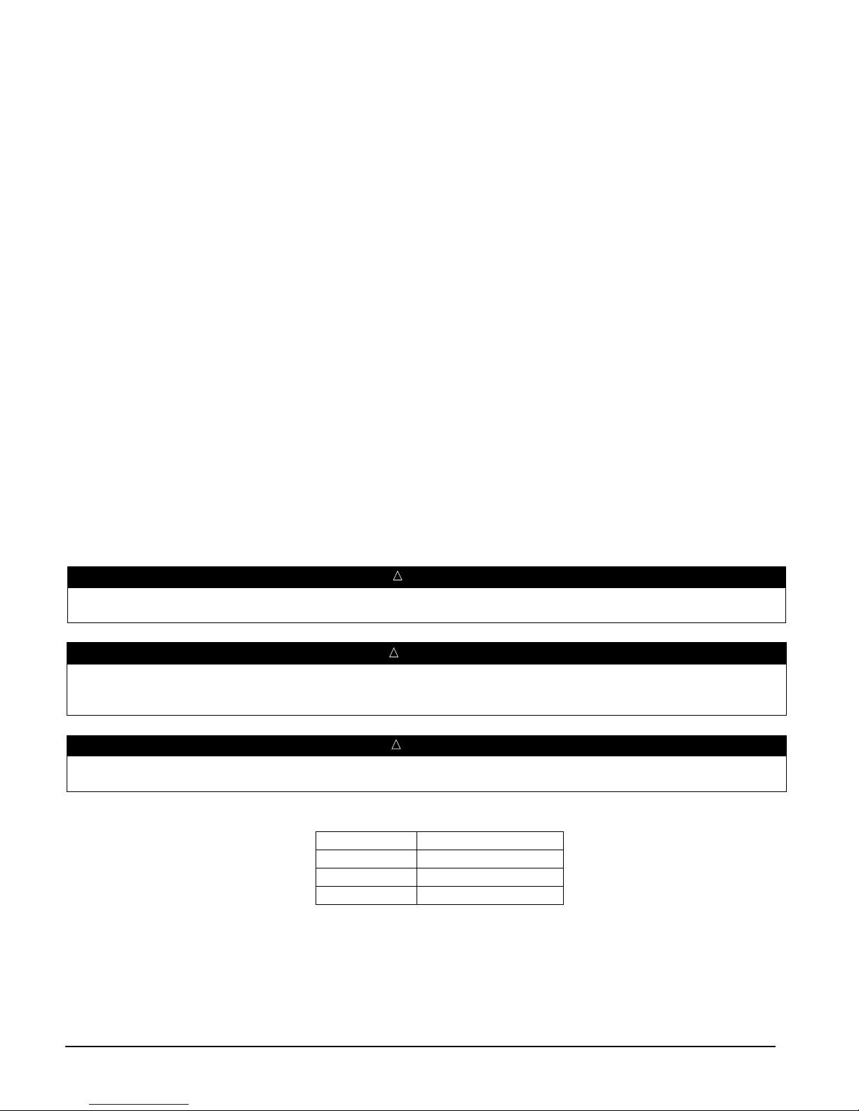
Hazard Identification
Dangers indicate a hazardous situation which will result in death or serious injury if not avoided.
Warnings indicate potentially hazardous situations, which can result in property damage, severe personal injury, or death if not
avoided.
Cautions indicate potentially hazardous situations, which can result in personal injury or equipment damage if not avoided.
©2012 Daikin.Illustrations and data cover the Daikin product at the time of publication and we reserve the right to make changes in design and
construction at anytime without notice.
™® The following are trademarks orregistered trademarks of their respective companies: BACnet from ASHRAE; LONMARK, LonTalk, LONWORKS, and the
LONMARK logo are managed, granted and used by LONMARK International under a license granted by Echelon Corporation; ElectroFin from AST ElectroFin
Inc.; Modbus from Schneider Electric; MicroTech II, Open Choices from Daikin;Loctite from Henkel Company; 3M, Scotchfil and Scotchkote from the 3M
Company; Victaulic from Victaulic Company; Megger from Megger Group Limited.


