Stuv STUV 16 User manual
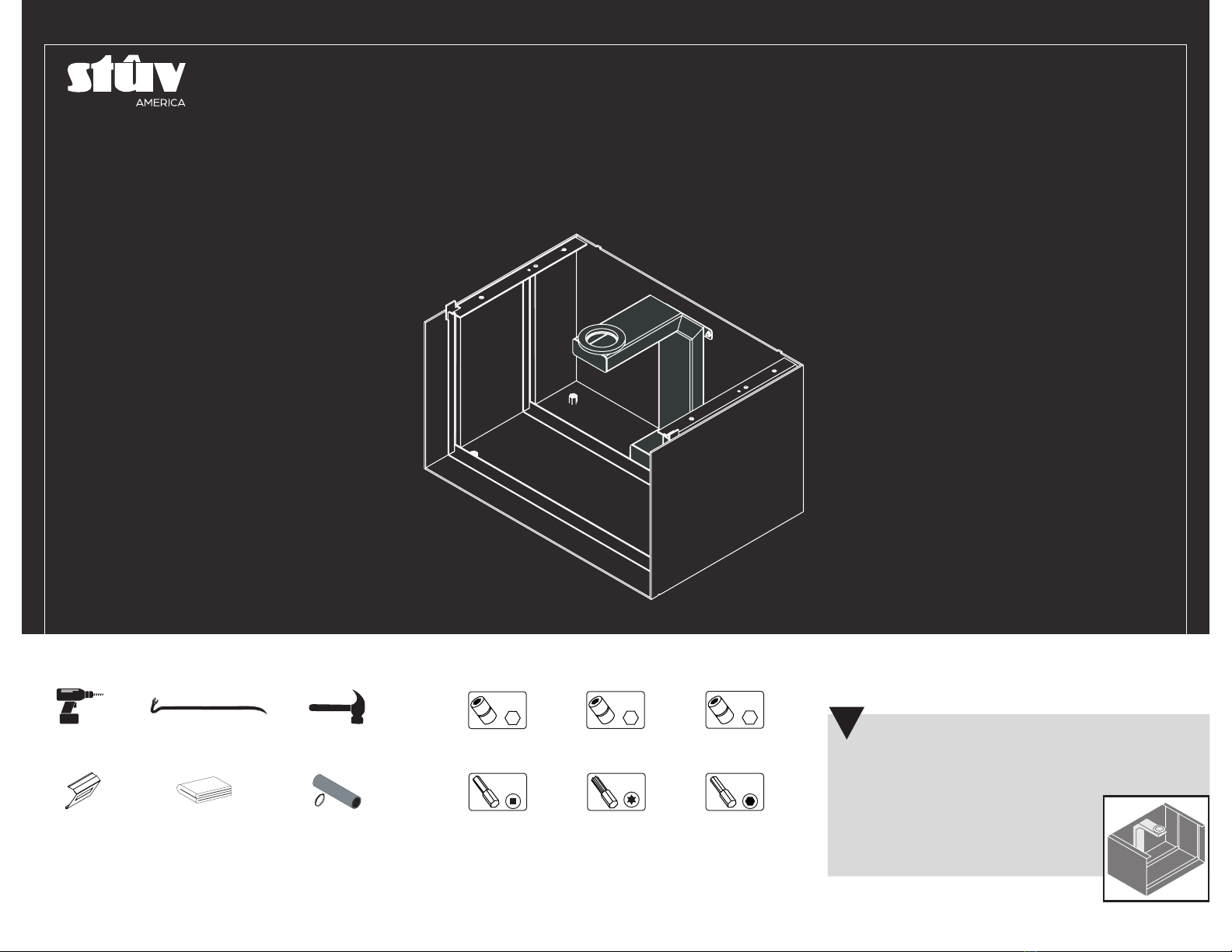
REQUIRED TOOLS REQUIRED HARDWARE
HammerImpact driver 8 mm
hex socket
5 mm
hex socket
No. 2
square bit
Crowbar
Torx 20 bit
10 mm
hex socket
Cube handles Protective fabric
or cardboard
10mm
#2 T20
8mm
H BASE
STÛV 16
INSTALLATION MANUAL
7mm
3mm
3 mm
hexagonal bit
Ø4’’Clamping collar
and flexible duct
(option)
EN
IMPORTANT
This document is an appendix to the Stûv 16
installation manual. For a successful installation,
it is important to follow these
instructions carefully. Look for
this symbol in the Stûv 16
installation manual to know
when to refer to this appendix.
!

1
DIMENSIONS

1
3DIMENSIONSHBASE STÛV16
.1 DIMENSIONS
SIDE VIEW FRONT VIEW
DESCRIPTION 16-58 16-68 16-78
H base AW1301001200 AW1301001300 AW1301001400
17 ⁄" A
39 ¾"
15 ¾"
⁄"
4"
2 ¾" 2 ⁄"
1 ⁄"
4 ⁄"
2 ⁄"
11 ¾"
3 ⁄"
2 ⁄"
2 ½"
11 ⁄"
BOTTOM VIEW M6x16 hex bolts
(4x)
3
5
2
Stûv 16-Cube
(sold separately)
H base
4
2
3
5
1
OPTION : AW1200200700
Outside air intake connector
M4 nuts (x4)
Air inlet channel
Cylindrical connector
Self-drilling screws (x2)
Offset reducer
4
1
.2 EXPLODED VIEW
1
Non-combustible*
Non-combustible*
*See Stûv 16-cube installation
manual for more details .
FRONT
VIEW A
16-58 22 ⁄ "
16-68 26 ¾"
16-78 30 ¾"

1
4DIMENSIONSHBASE STÛV16
All components added between the H base and the external dimensions of the
insulated shell (V) must be made of non-combustible materials.
The junction between the non-combustible material under the H base and the
non-combustible floor protection in front of the fireplace must be airtight to keep
embers from getting inside the wall or under the subfloor.
The red line on the illustration shows where to place the sealing
strip.
The V* dimension indicates the minimum measurement to
cover the insulated shell.
To make it easier to affix the wall finishing, we recommend
cutting the cement board wider to reach the wall structure's
wood frame. This will help make the two sides around the H
base more rigid.
The wood frame will therefore be used to affix both the drywall
and the cement board. If a structure is added around the H
base to affix the cement board, it must be made of a non-
combustible material.
PROTECTION OF THE COMBUSTIBLE MATERIALS
AFFIXING THE WALL FINISHING
It is mandatory to extend the non-combus-
tible floor protection under the H base. It is
also mandatory to protect the wall structure
by adding non-combustible materials verti-
cally on the sides and in the back.
W
39 ¾"
V*
additional
non-combustible
mandatory
non-combustible
extension
sealing strip
NOTE
These obligations must be
respected in addition to the
minimum clearances indicated on
the previous pages.
!
cement board
MODEL V W
16-58 29 ⁄" 22 ⁄"
16-68 33 ⁄" 26 ⁄ "
16-78 37 ⁄" 30 ¾"
cement board
drywall
combustible
(drywall)
combustible
non-combustible
(cement board)
Sealing strip
.3 INSTALLING A 16-Z WITH AN H BASE

2
INSTALLATION
2.1 UNPACKING .................................................................................................................................... 5
2.2 OPTION: OUTSIDE AIR INTAKE KIT ........................................................................................... 6
2.3 INSTALLING THE STOVE ............................................................................................................. 7
2.4 POSITIONING THE CUBE SHELL ................................................................................................ 9
6INSTALLATIONHBASE STÛV16
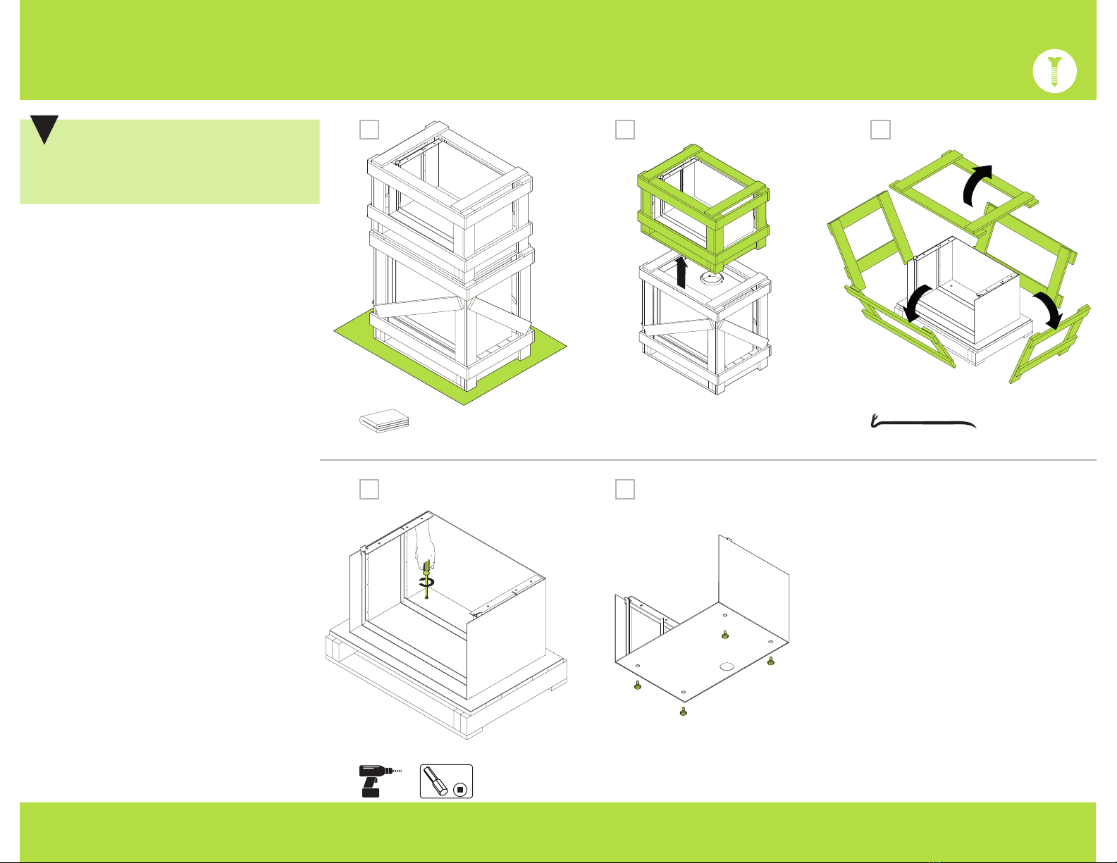
2.1 UNPACKING
Step 4 Remove the 4 screws securing the
H base to the pallet.
Step 5 In the complementary box
accompanying the Stûv 16, there is 4
leveling feet These are to be screwed
under the H base
Step 1 Protect the floor with a piece of
cardboard or a protective fabric before
unpacking the Stûv 16 and the H base.
Step 2 Separate the H base pallet from
the Stûv 16 pallet.
Step 3 Dismantle the pallet and check its
contents against the list on page 3. You
will need the Stûv 16 base plate for the
next several steps.
IMPORTANT
The paint is fragile. Be careful not to
scratch the H base with the nails in the
pallet when unpacking.
!
1
23
x4 x4
54
321
#2

7INSTALLATIONHBASE STÛV16
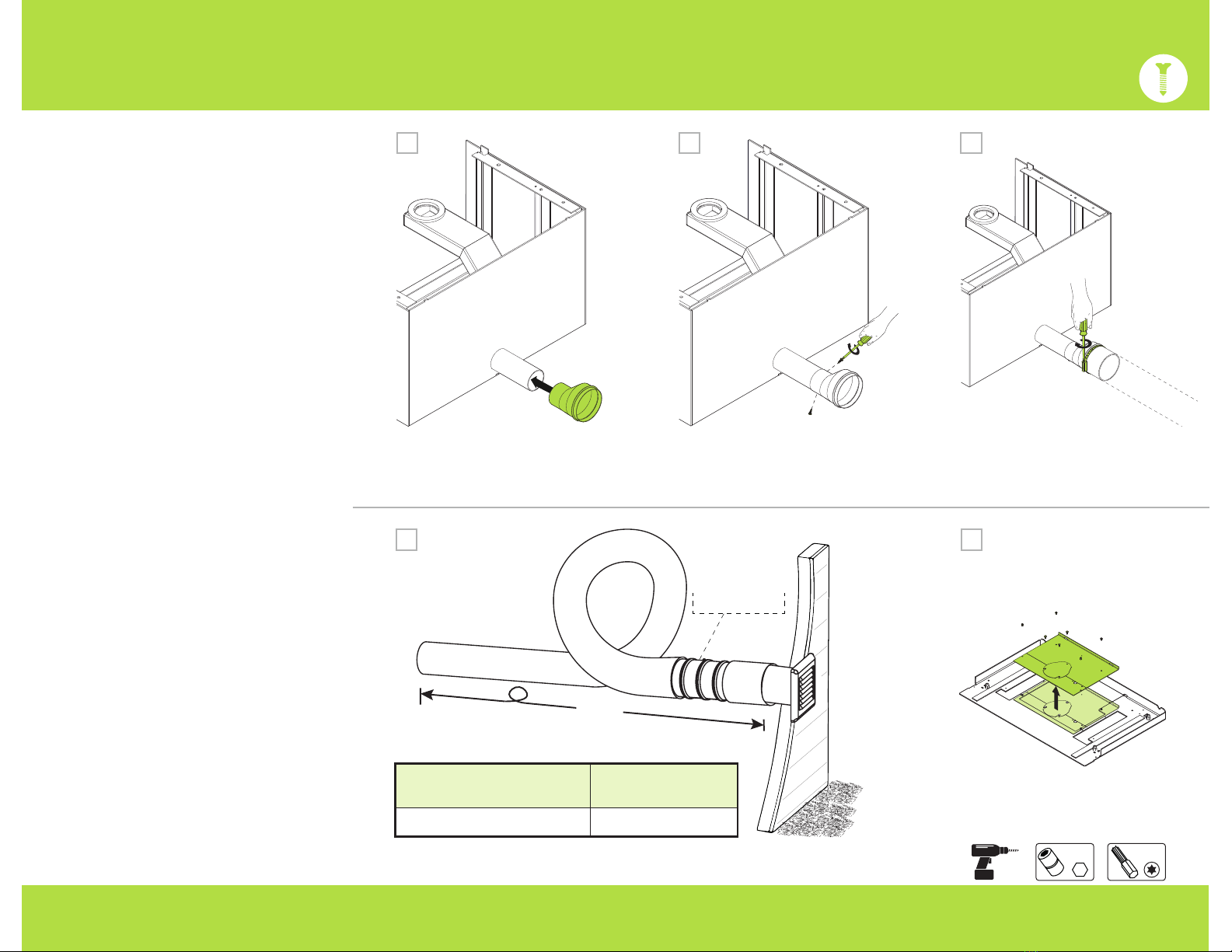
2.2 OPTION: OUTISE AIR INTAKE
7mm
Step 8 Fit the cylindrical connector into
the selected opening and insert it all the
way in.
Step 9 When installing the air inlet
channel, make sure both the circles from
the cylindrical connector and the air inlet
channel are aligned. See the sectional
view in the circle in Figure 9.
Step 10 Using the four (4) M4 nuts
provided, attach the air inlet channel to
the H base.
Step 6 The outside air connector can be
connected either at the bottom OR to the
back of the base. Using a hammer, knock
out the pre-cut circle in the base and the
air inlet channel.
Step 7 If connecting at the back, use
the pre-cut circle previously removed and
place it between the bottom of the air
inlet channel and the bottom of the base.
OR
1098
7
IMPORTANT
Only follow these steps if the outside air
intake option was selected.
If not, go to page 8.
!
6UNDER BEHIND
x4
8INSTALLATIONHBASE STÛV16
2.3 INSTALLING THE STOVE
Step 11 Slide the offset reducer onto the
cylindrical connector.
Step 12 Secure the cylindrical connector
and the reducer with the two self-drilling
screws provided.
Step 13 Connect the offset reducer to
the Ø4’’ outside air duct (not provided)
and secure with a clamping collar.
x2 131211
Step 14 In areas where winter
temperatures go bellow -10 °C / 14 °F, it
is mandatory that the duct leading to the
outside air have a minimum of 10' long.
It is recommended that you form a loop
with the flexible duct inside the wall.
An air damper is also recommended when
installing an outside air intake.
Step 15 Remove the air traps from the
Stûv 16 base plate. These items will not be
used in this installation.
10’
Air damper
14
Outisde air kit 4" air damper
AW12002000001 AW1200100300
15
7mm T20
9INSTALLATIONHBASE STÛV16
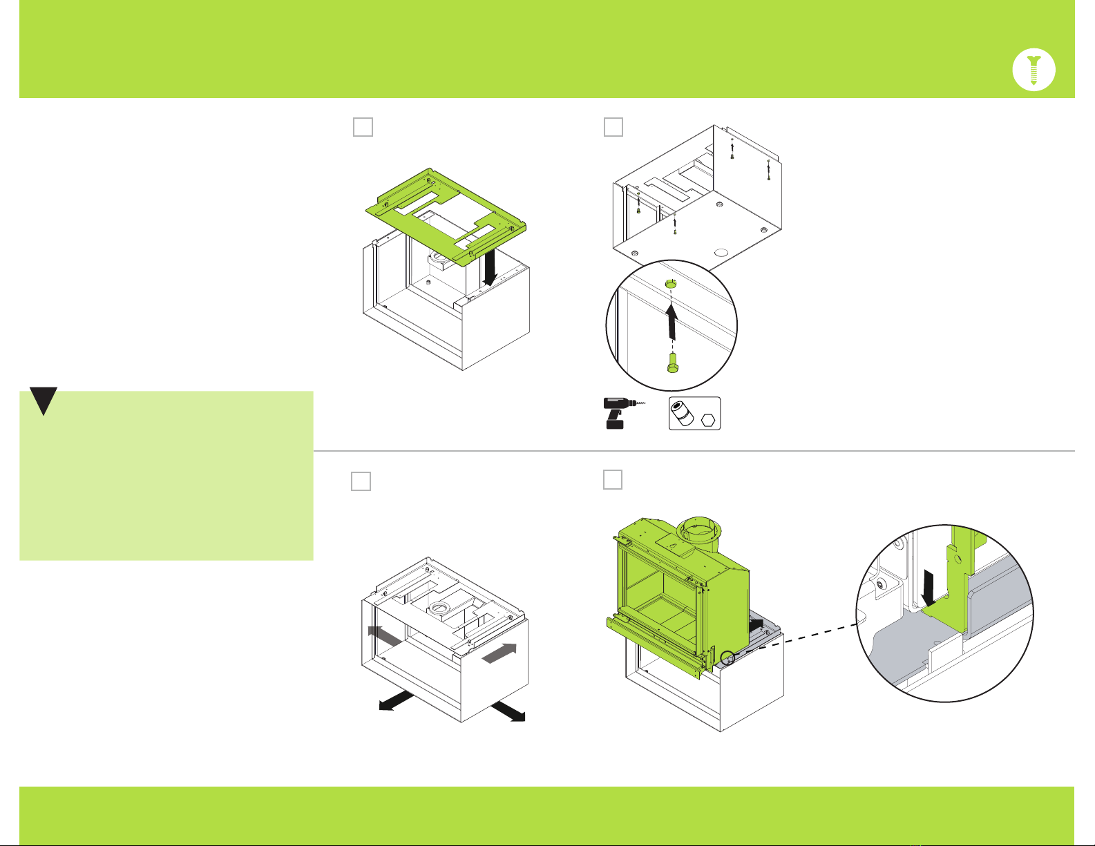
2
Step 16 Place the base plate on the H
base. Locate the threaded holes adjacent
to the leg insert notches.
Step 17 Thread the M6x16 hex bolts, but
do not screw them in completely.
ATTENTION
Confirm that the positioning respects
all the safety standards indicated in the
Stûv 16 installation manual.
The steps to follow for preparing the
stove without its shell can be found in
the Stûv 16-cube installation manual.
Refer to this manual for instructions.
!
18
1716
10mm
x4
1919
Step 18 Position the base in its final
location. A final adjustment may be need
to be once the cube shell is in place.
Step 19 Place the stove (without the
shell or door) on the base plate. Validate
the positioning by checking the notches
inserted in the cut-outs.
.3 INSTALLING THE STOVE
10INSTALLATIONHBASE STÛV16
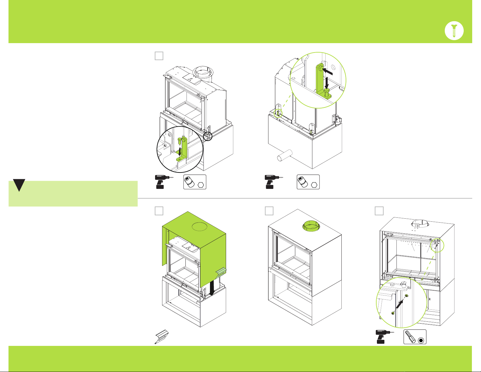
2.4 POSITIONING THE CUBE SHELL
Step 21 Use the cube handles to position
the shell on the stove.
Step 22 Align the cut-out in the shell
with the stove's flue.
Step 23 Secure the shell with the 4
screws in the front, starting with the lower
screws.
Step 20 Using the four connecting
brackets, M5x12 hex bolts and M5 nuts
supplied in the complementary enclosed
box, attach the stove and base plate
together on all sides (front, rear, left and
right).
CAUTION
The paint is fragile!
!
232221
2020
3mm
x4
8mm8mm

11INSTALLATIONHBASE STÛV16
2
7mm
.4 POSITIONING THE CUBE SHELL
Step 27 Check the adjustment at the
back of the stove: the depth and then
laterally. Confirm the alignment at the
front.
Step 28 Tighten the four M6 bolts under
the base plate to solidify it.
Step 24 To secure the upper part of the
shell and the stove, loosen the hex-head
screw.
Step 25 Rotate the lock until it fits around
the button-head screw.
Step 26 Tighten the screw.
4
321
2827
262524
10mm
x4
7mm
CAUTION
In order to increase the safety of your
installation, we recommend limiting
the storage of logs to the interior area
of the H base. Do not store any highly
flammable material, such as paper and
fire starters.
!!
CAUTION
!!
9310400022 | January 2022
And manufactured in North America by :
Stûv America inc. – Canada
stuvamerica.com
34, Boulevard de l’Aéroport
Bromont Qc Canada J2L 1S6
1-514-396-3463 | 1-866-487-7888
Stûv fireplaces are designed by:
Stûv sa – Belgique
stuv.com
Rue Jules Borbouse n°4 B-5170
Bois-de-Villers
Other manuals for STUV 16
1
Table of contents
Other Stuv Fireplace Accessories manuals


Popular Fireplace Accessories manuals by other brands


Lennox Hearth Products
Lennox Hearth Products Decorative Style View MPB-45 installation instructions

Valor
Valor GV60CKO installation manual

Valor
Valor G3 Series installation instructions

Regency
Regency HEAT WAVE 946-556 manual

Napoleon
Napoleon GA-566 installation instructions

Boulevard
Boulevard DFEV60LSS-1 Installation instruction guide

Quadra-Fire
Quadra-Fire LOGS-QFI30 Log Placement Instructions

Hearth & Home
Hearth & Home FOLIO Series installation instructions

Valor
Valor G3.5 Series installation manual

Valor
Valor MADRONA Series installation instructions

IHP
IHP SV4.5HTKCT installation instructions

pleasant hearth
pleasant hearth OFP24WG quick start guide