
PAGE 15 STUV 6 FREESTANDING | SPECIFICATIONS & MANUFACTURER INSTALLATION GUIDE
^
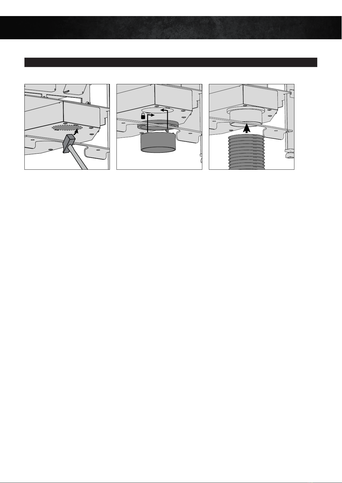
5. AIR INTAKE
COMBUSTION AIR INLET
OPTION 1: AIR FROM THE ROOM
You can chose the combustion air to be drawn directly from the room. You must make sure the room is sufficiently ventilated when the stove is in
use.
NB
Beware of active air extractive systems (cooker hood, air-conditioning unit, controlled mechanical ventilation, another stove etc.) in the same
space or in a neighbouring room. They also use up a lot of air, could cause low pressure in the area and disrupt the smooth running of the stove. It
is also important to make sure that the configuration chosen is completely compatible with local and national regulations.
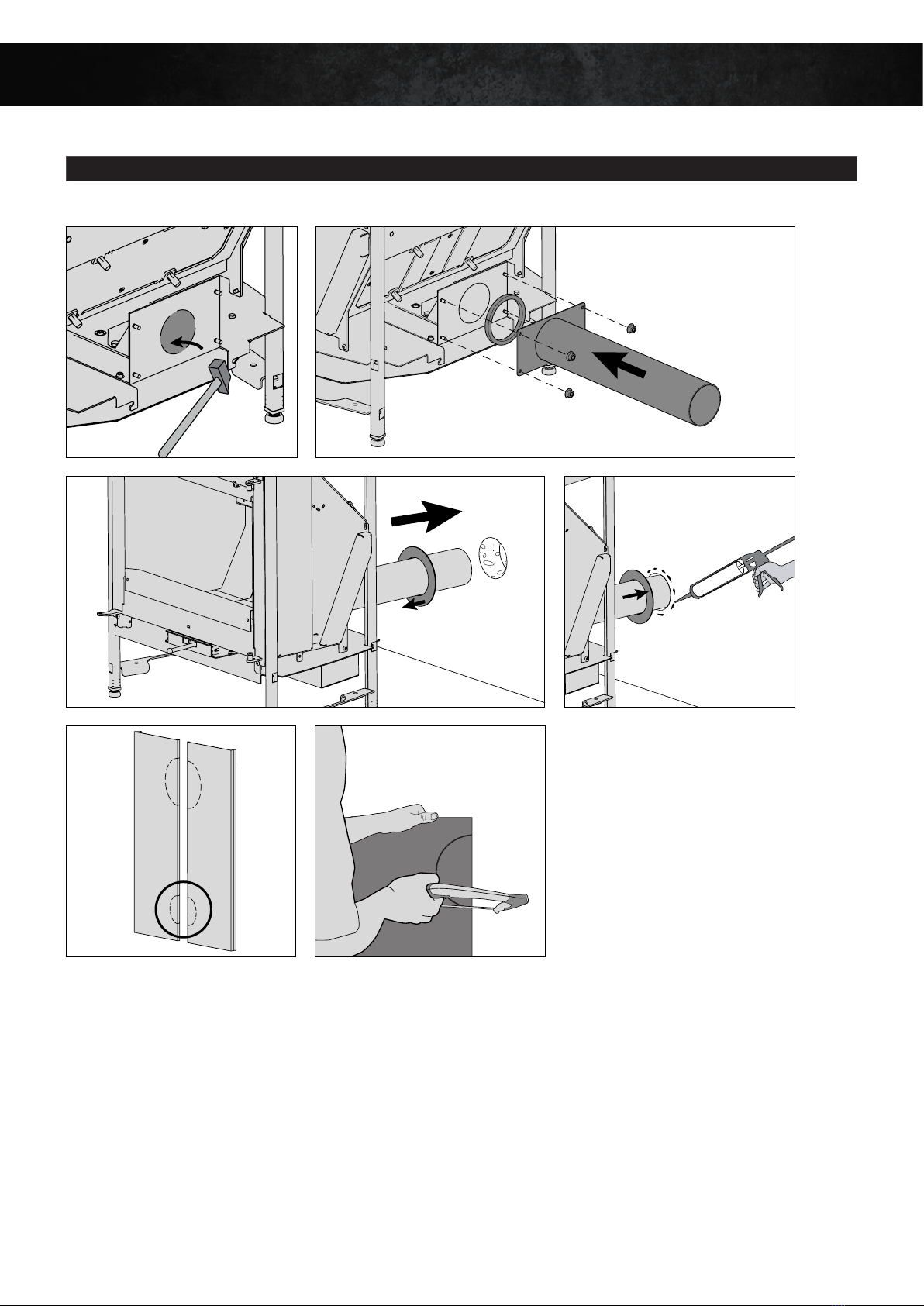
OPTION 2: AIR FROM OUTSIDE
External air inlet
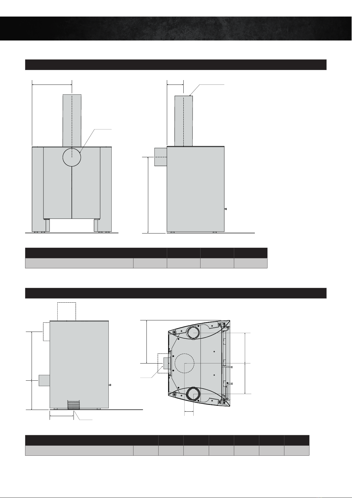
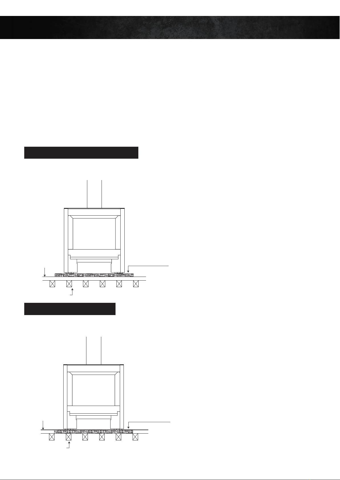
An adequate air inlet should ideally be pointing either: - vertically under the stove, to be connected via a 80mm nozzle [figure 1].
- horizontally behind the stove, to be connected using an external air inlet kit at the back and a 80mm nozzle [figure 2].
This air inlet should preferably come from a ventilated cavity, a ventilated space (cellar), directly from the outside (mandatory in some countries).
In this case, be aware of the risk of condensation.
The duct that brings in the external air...
... will be protected from the outside with a grill where the cross-section of the clearance is at least equivalent to the cross-section of the air inlet.
Watch out for water getting in as well as wind, as these could make the system ineffective.
.... will be as short as possible to prevent pressure loss and make sure the house doesn’t get cold.
If you use our standard 80mm flexible duct, we recommend a maximum length of 2m and no more than 4 bends. If you do not follow these
recommendations, you will need to compensate by having a larger diameter and/or a more flexible tube.
Make sure you do not squash the duct.
12


 owner's manual")


