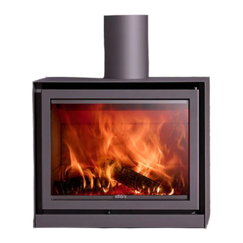
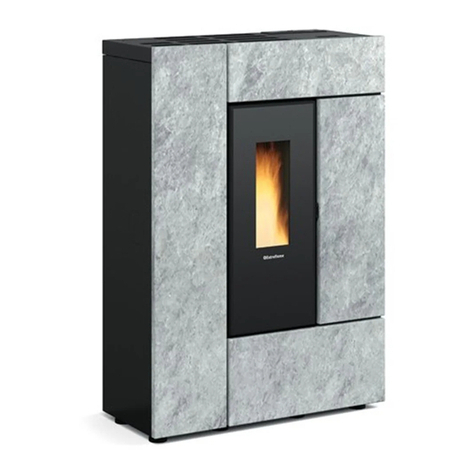
Stuv 21 Series User manual

S
T
U
^
V
21:
SPECIFICATIONS &
MANUFACTURER
INSTALLATION
GUIDE

1. PRELIMINARY
INSTALL
INFORMATIONS
STU
^
V
21
|
MODEL
SPECIFICATIONS
PAGE
2
In relation to the installation and use of this appliance, the installer and the user should strictly
adhere to local and national regulations as well as Australian & New Zealand Standards AS/NZS
2918:2001. They should also follow
the instructions detailed in the Stûv 21 installation and user
manual. Safe operation of the fireplace is directly dependent thereon. The liability of the manufacturer
can neither be retained nor assured following failure of installation or incorrect use which is not
compliant with AS/NZS 2918:2001.
As each installation is different, a qualified and licensed trade’s professional should take all required
preliminary precautions depending on the technical elements inherent to each job.
In-observance of the assembly instructions in conjunction with AS/NZS 2918:2001 entails the liability
of the person who carries it out.
Fireplace structure and finishes shall be to your own design providing the exact and minimum
dimensions are maintained.
The floor must have adequate strength to support the fireplace. N.B. Timber floors may require
additional reinforcing.
Construction of the fireplace structure from floor to ceiling shall be: solid brick (110mm minimum),
Silicate board (40mm), stone (100mm minimum) or AAC block (75mm minimum).
When installed on a combustible floor surface the Stûv 21 firebox must be positioned on top of an
18mm cement sheet floor plate and raised to a minimum height of 150mm using the appliance
adjustable feet.
As a result of faulty assembly, use of parts or additional components not supplied by the
manufacturer/distributor, and/or modifying of the appliance or components will result in inferior or
unsafe operation. Should this occur the manufacturer/distributor bears no liability, and will result in a
null and void product warranty.

2.
SPECIFICATIONS
STU
^
V
21
|
MODEL
SPECIFICATIONS
PAGE
3
SINGLE
FRONTED
MODEL
-
STUV
21
DIMENSIONS
(mm)
OTHER
DETAILS
STUV 21 / 95 SF STUV 21 / 105 SF STUV 21 / 125 SF STUV 21 / 135 SF
OUTPUT KW 10kw to 18kw 7kw to 19kw 11kw to 23kw 11kw to 21kw
HEATING CAPACITY 120m2125m2145m2130m2
MINIMUM FLUE HEIGHT 4.5m 4.5m 4.5m 4.5m
WEIGHT (excluding zero clearance casing) 292kg 224kg 305kg 286kg
MAX LOG SIZE 60cm 80cm 100cm 100cm
ACTIVE FLUE SIZE
STUV 21 / 95 SF STUV 21 / 105 SF STUV 21 / 125 SF STUV 21 / 135 SF
A950 1050 1250 1350
B1455 1040 1295 1040
C590 496 563 500
D770 870 1070 1170
E615 400 535 400
ACTIVE FLUE SIZE
300mm,350mm
ADDITONAL FLUE LINERS
250mm
250mm
300mm,350mm 250mm,300mm
200mm 300mm
350mm,400mm

2.
SPECIFICATIONS
STU
^
V
21
|
MODEL
SPECIFICATIONS
PAGE
4
Extended exhaust plate
STÛV
21
/
95
DF
STÛV
21
/
125
DF
A
950
1250
B
1455
1295
C
670
670
D
770
1070
E
615
535
OTHER
DETAILS
STÛV
21
/
95
DF
STÛV
21
/
125
DF
OUTPUT
KW
12kw
to
27kw
14kw
to
27kw
HEATING
CAPACITY
165m2
165m2
MINIMUM
FLUE
HEIGHT
4.5m
4.5m
WEIGHT
(excluding
zero
clearance
casing)
297kg
310kg
MAX
LOG
SIZE
700mm
1000mm
ACTIVE
FLUE
SIZE
250mm
300mm
ADDITIONAL FLUE LINERS
300mm, 350mm
350mm, 400mm
DOUBLE
FRONTED
MODEL
-
STUV
21
DIMENSIONS
(mm)

3. CLEARANCES
-
IMPORTANT
STU
^
V
21
|
MODEL
SPECIFICATIONS
PAGE
5
When installed on a combustible floor surface the Stûv 21 firebox must be positioned on top of an 18mm cement
sheet floor plate and raised to a minimum height of 150mm using the appliance adjustable feet.
When installed on a non-combustible floor the fireplace can be installed directly onto the floor and adjusted in
height using the adjustable feet.
In a cavity built out of bricks, block work or 75mm ACC block the appliance must be installed with a minimum
gap of 50mm at the back and on
the sides.
In a cavity built out of silicate boards the appliance must be installed with a minimum gap of 100mm at the back
and on the sides.
Only non-combustible material (silicate board, Promatect H 12mm or brickwork) shall be used on the front wall
of the
cavity.
All internal framework above the appliance shall be made of non-combustible material.
The
cavity
above
the
appliance
must
be
capped
and
must
have
a
minimum
of
2500cm2
of
venting.
The appliance must be fitted with the standard triple skin flue.
To conform to the requirement of the joint AS/NZS 2918:2001 the appliance must be bolted down to comply
with the seismic restrain provisions.

4. INSTALLATION
-
FLOOR
PREPARATION
STU
^
V
21
|
MODEL
SPECIFICATIONS
PAGE
6
The Stûv 21 can be installed straight
onto the surface with no prior
preparation required.
NON-COMBUSTIBLE
FLOOR
The Stûv 21 must be installed on
a 18mm tick cement sheet plate
(minimum) and raised using the
appliance’s adjustable feet so that the
bottom edge of the firebox door is at
least 300mm from the floor.
BRICK
WORK
50mm
AIR
GAP
18mm
CEMENT
SHEET
TIMBER
FLOOR
COMBUSTIBLE
FLOOR
NON-COMBUSTIBLE
SURFACE
300mm
minimum
COMBUSTIBLE
SURFACE

STU
^
V
21
|
MODEL
SPECIFICATIONS
PAGE
7
NON-COMBUSTIBLE
FLOOR
CAVITY
LID
30MM
SILICATE
BOARD
70mm
SILICATE
BOARD
COMBUSTIBLE
WALL
NON
COMBUSTIBLE
BOARD
100mm
AIR
GAP
50mm
AIR
GAP
NON-COMBUSTIBLE
FLOOR
FRONT
BACK

STU
^
V
21
|
MODEL
SPECIFICATIONS
PAGE
8
When installed on a combustible floor surface the Stûv 21 firebox must be positioned on top of a 18mm cement
sheet floor plate and raised to a minimum height of 150mm using the appliance adjustable feet.
STÛV
21
/105
SF
STÛV
21
/
135
SF
STÛV
21
/
95 SF/DF
STÛV
21
/
125
SF/
DF
A
1300
1600
1200
1500
B
1140
1140
1555
1395
C
150
150
150
150
D
800
800
800
800

STU
^
V
21
|
MODEL
SPECIFICATIONS
PAGE
9
NON-COMBUSTIBLE
FLOOR
CAVITY
LID
30MM
SILICATE
BOARD
NON
COMBUSTIBLE
BOARD
BRICKWORK
50mm
AIR
GAP
NON-COMBUSTIBLE
FLOOR
FRONT
BACK

STU
^
V
21
|
MODEL
SPECIFICATIONS
PAGE
10
For installations where a combustible floor is
situated in front of the Stûv 21 a non combustibe
hearth (floor protector) is required.
For installations where
t
he
Stûv 21
is raised and an
outside air kit is being
fitted below the appliance
there is an
OPTIONAL STEEL
STAND available.

STU
^
V
21
|
MODEL
SPECIFICATIONS
PAGE
11
The minimum flue run for all Stûv fireplaces must be 4.5m from
the
appliance to the top of the external flue.
Coming off of the appliance the flue must run straight vertically for a
minimum of 900mm before a bend or elbow can be included in the flue
run. Elbows or bends in the flue must be a maximum angle of 45º
STÛV
21
/105
SF
STÛV
21
/
135
SF
STÛV
21
/
95
DF
STÛV
21
/
125
DF
A
200mm
250mm
250mm
300mm
B
250mm
300mm
300mm
350mm
C
300mm
350mm
350mm
400mm
4500mm
MIN
FLUE SYSTEM (Triple flue system)

STU
^
V
21
|
MODEL
SPECIFICATIONS
PAGE
12

STU
^
V
21
|
MODEL
SPECIFICATIONS
PAGE
13

4. INSTALLATION -
SHELVES
STU
^
V
21
|
MODEL
SPECIFICATIONS
PAGE
14
A
COMBUSTIBLE
SHELF

5.
C0NVECTION
STU
^
V
21
|
MODEL
SPECIFICATIONS
PAGE
15
Convection air inlets are through single wall flexible ducts.
Convection air outlets must be through insulated double wall ducts.
It is important that the air flow is continuous. It is therefore forbidden to remove the air from a room and
send it to another airtight room.
Use a
minimum
of
2
fresh
air inlets
and
2
hot
air outlets.
The
distance
between
the
ceiling
and
the
center
of
the
hot
convection
grill
must
be
at
least
35cm.
The horizontal distance between the hot air convection grill and the appliance cannot be greater than 3m.
The vertival distance between the hot air convection grill and the appliance is not limited.
See
fig
I
and
J.
Figure
I
35cm
(minimum)
155cm
(minimum
-
from
the
base
of
the
appliance)
CONVECTIONAIRINLET
CONVECTION AIR OUTLET
35cm
(maximum)

5.
C0NVECTION
STU
^
V
21
|
MODEL
SPECIFICATIONS
PAGE
16
The convection air never comes into contact with the fire. The convection is an independant air channel.
The air circulates around the combustion chamber, gets hot and goes out through convection grates in
the same room or in other rooms.
CONVECTION
AIR
CIRCULATION
CONVECTION
AIR
INLET
CONVECTION
AIR
INLET
HOT AIR
OUTLETS
CONVECTION
AIR
CIRCULATION

6.
C0MBUSTION
STU
^
V
21
|
MODEL
SPECIFICATIONS
PAGE
17
When operating with an open fire, the Stûv 21 consumes a large amount of air. Therefore, we recommend
providing an external air supply, although this is not mandatory.
A sufficient air inlet must be created under the stove, at the front. When not using the air intake box with
connected duct, the base of the fire must be supplied with fresh air. The fresh air must come from a ventilated
empty space, a ventilated room or from outside the house (mandatory for passive/air tight buildings).
ONLY
DUCT
THE
FRESH
AIR
INLET
TO
THE
APLLIANCE
USING
THE
INTAKE
BOX.
The air intake, which varies depending on the model, should ideally be located beneath the front of the unit
and incorporate a shut-off register (fig a).
Ideally the fresh air inlet would be fitted with a closure valve (fig e and f) to prevent the room from becoming
cold when the appliance is not in use. It should ideally be located as close as possible to the outside wall and
controlled from inside the room.
a. COMBUSTION
AIR
CIRCULATION b. COMBUSTION
AIR
INLET
c. COMBUSTION
AIR
INLET
WITH
DUCTED
INTAKE
BOX
d.
COMBUSTION
AIR
INTAKE
BOX (Double-sided fires x 2)
e. EXTERNAL
COMBUSTION
AIR
INTAKE
f.
EXTERNAL
COMBUSTION
AIR
INTAKE

6.
C0MBUSTION
STU
^
V
21
|
MODEL
SPECIFICATIONS
PAGE
18
INLET
DIAMETER
STÛV
21
/
105
SF
150mm
STÛV
21
/
135
SF
150mm
STÛV
21
/
95
DF
150mm
STÛV
21
/
125
DF
150mm
EXTERNAL
COMBUSTION
AIR
(INTAKE
BOX)
EXTERNAL
COMBUSTION
AIR
(NO
INTAKE
BOX)
INTERNAL
COMBUSTION
AIR
(INTAKE
BOX)
EXTERNAL
COMBUSTION
AIR DOUBLE SIDED (INTAKE
BOX)
COMBUSTION
AIR
INLET

STU
^
V
21
|
MODEL
SPECIFICATIONS
PAGE
19
TEST
REPORT
NO
ASFT18044
(PRELIMINARY
REPORT)
TESTING
LABORATORY:
Australian
Solid
Fuel
Testing
MANUFACTURER:
Stûv
MODEL:
Stûv
21
WORK
REQUESTED:
Compliance
with
AS/NZS2918:2001
Standards
ISSUE
DATE:
4/05/2018
CONCLUSION:
The Stûv 21 Inbuilt appliance installed with a triple skin flue system, conforms to the requirements
of Australian/New Zealand Standard 2918:2001, with respect to floor, side wall and rear wall
surface temperatures, when tested in accordance with Appendix B of AS/NZS2918;2001.

STU
^
V
21
|
MODEL
SPECIFICATIONS
PAGE
20
What
you
should
burn
•
Untreated,
air
dried
softwood
•
Split logs
with a
humidity
content
of less
than
20%
Do not burn
•
Trash
•
Painted
plastic
•
Coated
or
preservative
treated
wood
•
Waste
or
black
coal
•
Inflammable
liquids
•
Fire
gels
•
Moist
wood
with
a
residual
humidity
content
of
more
than
20%
(this
may
cause
soothing
of
the
chimney).
Other manuals for 21 Series
6
This manual suits for next models
6
Table of contents
Other Stuv Stove manuals
Popular Stove manuals by other brands

Quadra-Fire
Quadra-Fire GARN-DMBK-IPI-B installation manual

COMPANION
COMPANION PRI2223 owner's manual
Premier
Premier EF-0578E instruction manual
Dimplex
Dimplex LVT20-AU instruction manual
LA NORDICA
LA NORDICA Termo Isotta DSA Instructions for installation, use and maintenance

klover
klover PELLET FIRE PLACE 22 Instructions for installation, use and maintenance manual
