Stuv 6-IN User manual

T25
STÛV 6-IN
INSTALLATION MANUAL
Keep these instructions for future reference
EN
Hammer
Measuring
tape
Crowbar
Cutting pliers
Chimney kit
(flexible or rigid)
Impact drill
Level
5 mm
hex bit
5mm
Torx 20 bit
T20
Protective fabric or
cardboard
Stûv handles
REQUIRED TOOLS REQUIRED HARDWARE REQUIRED MATERIAL
Pliers
T30
Torx 30 bit
8 mm
hex socket
8mm
7mm
7 mm
hex socket
Torx 25 bit
No. 2
square bit
#2
Ø4’’ clamping collar
and flexible duct
(option)
No. 8
wood screw
10 mm
hex socket
10mm
No. 10
concrete screw

2
STÛV 6
APPENDICES
This manual explains how to carry out a standard installation of a Stûv 6 unit. To
install a frame, an air damper or any other option, it is necessary to respect, when
applicable, certain particularities that are outlined in the appendices provided. If
the appendices are missing, contact customer service and request the necessary
instruction manual(s), mentioning the code(s) under the icons below.
Look for these symbols. They signal a change from the standard installation. It is
very important to skim through the manual and appendices before starting and to
follow the instructions closely during installation to ensure no steps are omitted.
Keep all instruction manuals provided close at hand to have all the information
needed and to ensure proper and safe installation.
Thank you for choosing a
Stûv fireplace! It has been
designed to offer maximum
pleasure, comfort and
safety. The utmost
care has been taken in
manufacturing this product.
If, despite this, you should
still find a flaw, please
contact your dealer.
THIN EDGE FRAME
9310400023
PICTURE TYPE FRAME
9310400024
AIR DAMPER
9310400019

3
STÛV 6
TABLE OF CONTENTS
1. CERTIFICATION 4
1.1 Certification
1.2 Technical Specifications
1.3 Marking Label
1.4 Safety Instructions
2. COMPONENTS 9
2.1 List of Components
2.2 Frames
2.3 Optional Kits
VISSERIE À PRÉVOIR
6. USE 35
7. MAINTENANCE 41
VISSERIE À PRÉVOIR
8. WARRANTY 45
6.1 Wood Selection
6.2 Safety
6.3 Door Handling
6.4 Starting the Fire
6.5 Reloading the Fire
6.6 Ash Removal
7.1 Glass Pane and Seals
7.2 Creosote and Chimney-Sweeping
7.3 Component Replacement
8.1 Warranty Details
8.2 Warranty Form
3. DIMENSIONS 14
3.1 Overall Dimensions
3.2 Dimensions of the Connectors
3.3 Dimensions of the Opening
3.4 Non-Combustible Materials
3.5 Risk Area
3.6 Convection Air
3.7 Combustion Air
VISSERIE À PRÉVOIR
4. INSTALLATION 22
4.1 Combustion
4.2 Unpacking and Moving
4.3 Disassembly
4.4 Connection to the Combustion
Air Intake
4.5 Reassembly and Chimney
5. CHIMNEY 32
5.1 Dimensions and Certification
5.2 Typical Installation
5.3 Connection to a Chimney Pipe
5
5
6
7
10
12
13
36
37
38
38
40
40
42
42
43
46
47
15
16
17
18
20
20
21
23
24
25
27
29
33
33
34

1.1 CERTIFICATION ............................................................................................................................ 5
1.2 TECHNICAL SPECIFICATIONS ................................................................................................... 5
1.3 MARKING LABEL ......................................................................................................................... 6
1.4 SAFETY INSTRUCTIONS ............................................................................................................. 7
1
CERTIFICATION

5
1
CERTIFICATIONSTÛV 6
.1 CERTIFICATION
Tested and certified by CSA
as for standard:
ULC STD S 628 & UL STC 1482-7
EPA 2020 CRIB WOOD
CUS
Before installing and using this Stûv unit,
read thie entire manual and contact
the local authorities to obtain a building
permit. Take note of all applicable
regulatory requirements.
This unit must be installed by a qualified
professional. Improper installation could
result in a fire.
The instructions for the installation of
this wood-burning fireplace comply with
the above-mentioned standards. They
must be closely followed to eliminate
the risk of serious problems.
Do not install the fireplace in a mobile
home. Do not connect the fireplace to
a hot air distribution system.
To reduce the risk of fire, read this
manual carefully before installing or
using the fireplace. If the installation
instructions are not followed and the
fireplace is improperly installed, the risk
of an incident occurring increases. This
can result in fire, property damage,
bodily injury and even death.
Keep these instructions for future
reference.
NOTE
We strongly recommend that our products be installed
and maintained by professionals certified by the
Association des Professionnels du Chauffage if you are
in Quebec or by Wood Energy Technical Training for the
rest of Canada, and by the National Fireplace Institute
in the United States.
!
.2 TECHNICAL SPECIFICATIONS
1
STÛV 6 66x50 76x60
Maximum power ( BTU) 34,000* 48,000**
Performance 68.4% 68.3%
Fine particle emissions 1.93 g/h 1.89 g/h
Max. log length 16" 20"
Weight 165 lb. 200 lb.
Combustion chamber volume 1.08 ft.31.58 ft.3
Wood consumption⁄H 2.7 lb. 3.9 lb.
Fuel Cord wood
This manual describes the installation and operation of the Stûv 6-in wood heater.
This heater meets the 2020 U.S. Environmental Protection Agency's crib wood
emission limits for wood heaters sold after May 15, 2020.
*Under specific test conditions this heater has shown to deliver heat at rates ranging
from 14 802 to 17121 Btu/hr.
**Under specific test conditions this heater has shown to deliver heat at rates
ranging from 22 079 to 23 338 Btu/hr.
United States Design Patent No. US D898,173 S
6
1
CERTIFICATIONSTÛV 6
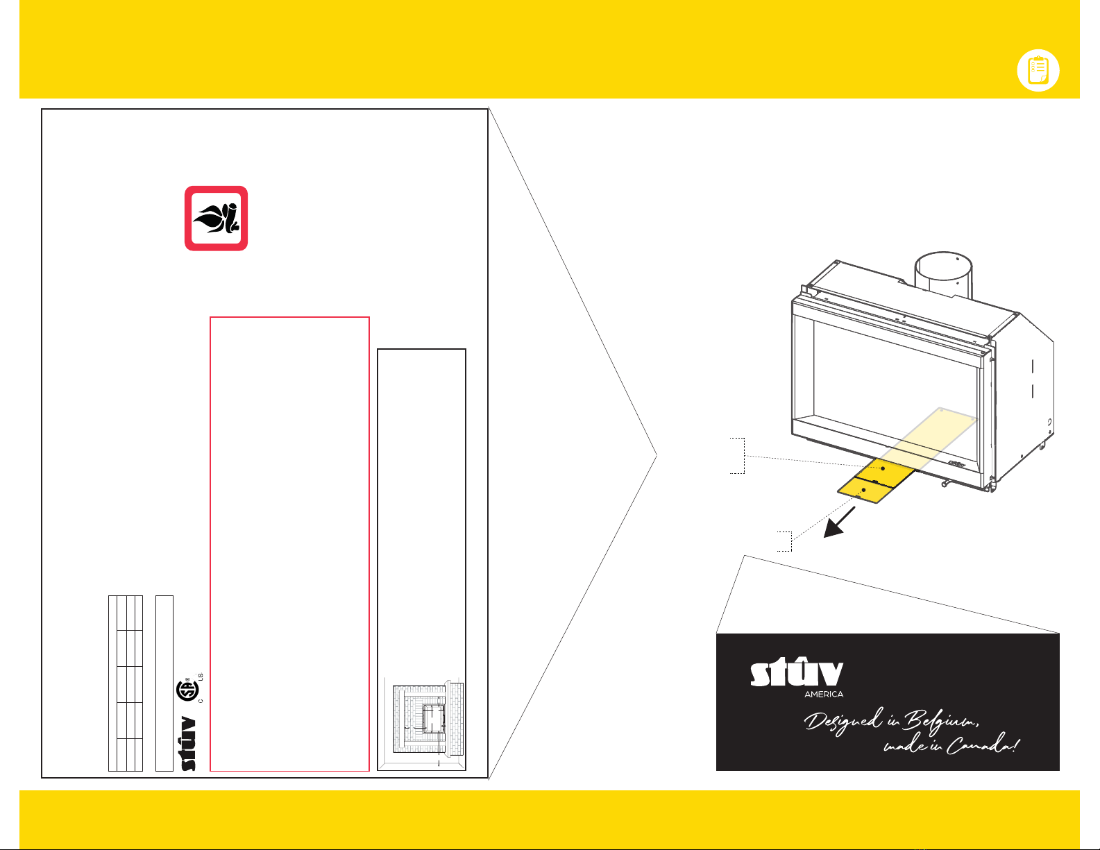
.3 MARKING LABEL
Marking
label
This Stûv fireplace must be registered to be covered by the warranty. Please refer to
the last section of this document for guidance.
The self-adhesive marking label and the riveted label with the serial number
are located in the drawer under the combustion chamber. They contain all the
information needed to register this product.
Serial number
A-000 000
- Fuel : Cord wood Only.
- This fireplace has been altered to accommodate a fireplace insert and should
be inspected by a qualified person prior to re-use as a conventional fireplace.
- Refer to local building code for heart extension dimensions.
- For safe operation, install and use only in accordance with Stûv America's
installation and operating instructions.
- Replace glass only with Stûv's ceramic glass 4mm thick.
- Do not operate unit with doors open and load on open fire door.
- Components used with fireplace must be listed. See owners manual.
- Contact your local building or fire officials about restrictions
and installation inspections in your area.
- Do not overfire - If stove or chimney connector glows, you are overfiring.
- Do not connect this unit to a chimney flue serving another appliance.
- Inspect and clean chimney frequently - Under certain conditions of use,
creosote buildup may occur rapidly.Inspect and repair wood heater for
proper operation
- Do not use grate or elevate fire. Build wood fire directly on hearth.
- This wood heater needs periodic inspection and repair for proper
operation. Consult the owner’s manual for further information. It is against
federal regulations to operate this wood heater in a manner inconsistent
with the operating instructions in the owner’s manual.
- CAUTION: Hot parts. Do not operate unit with damper removed.
- Combustible : Bois de corde seulement.
- Ce foyer peut avoir été modifié pour accueillir un encastrable. Il doit être remis dans son état
d'origine avant d'être utilisé comme foyer à combustible solide.
- Se référer au code du batiment local pour le prolongement de l'âtre.
- Pour un fonctionnement sécuritaire et conformément au règlements fédéraux, suivre la notice
d'installation et le mode d'emploi de Stûv America.
- Remplacer le verre uniquement par un verre de céramique Stûv de 4mm d'épaisseur.
- Ne pas utiliser l'appareil les portes ouvertes et charger seulement à feu ouvert.
- Les composantes utilisées dans l'appareil doivent être répertoriées. Voir la notice d'utilisation.
- Communiquer avec les autorités locales en matière de construction ou d'incendie pour
connaître les restrictions et inspections d'installation dans votre région.
- Ne pas chauffer au point ou des parties deviennent rougeoyantes.
- Ne pas relier cet appareil à un conduit de cheminée servant un autre appareil.
- Inspecter et nettoyer la cheminée fréquemment - Dans certaines conditions d'utilisation,
l’accumulation de créosote peut se faire rapidement. Inspecter et réparer l’insert pour assurer
le bon fonctionnement.
- Ne pas utiliser de chenet. Ne pas surélever le feu. Brûler le bois directement au fond de l'âtre.
- Cet insert a besoin d'inspection et d'entretien périodiques pour sa bonne utilisation. Consultez
le manuel d'utilisation pour davantage d'informations. L'utilisation contraire au manuel
d'utilisation représente une violation de la loi fédérale.
- ATTENTION : Pièces chaudes. Ne pas faire fonctionner avec le clapet retiré.
This fireplace has been altered to accommodate a fireplace insert
and should be inspected by a qualified person prior to re-use as a
conventional fireplace.
Ce foyer a été équipé d’un insert récupérateur de chaleur et devra
être inspecté par une personne qualifiée pour être à nouveau utilisé
comme un foyer conventionnel.
!CAUTION !
DO NOT REMOVE THIS LABEL / NE PAS RETIRER CETTE ÉTIQUETTE
The minimum clearances are indicated for all types of combustible materials (e.g.: wood, gypsum, etc.).
Les dégagements minimaux indiqués sont pour tous matériaux combustibles (ex. : bois, gypse, etc.).
HOT WHILE IN OPERATION DO
NOT TOUCH, KEEP CHILDREN,
CLOTHING AND FURNITURE
AWAY. CONTACT MAY CAUSE
SKIN BURNS. SEE NAME-PLATE
AND INSTRUCTIONS.
CHAUD LORSQU’EN FONCTION.
GARDER LES ENFANTS,VÊTE-
MENTS ET MEUBLES HORS DE
PORTÉE. TOUCHER L’APPAREIL
POURRAIT CAUSER DES BRÛ-
LURES. VOIR LA FICHE SIGNALÉ-
TIQUE ET INSTRUCTIONS.
C
E
A
B
G
D
A: 66x50 : 26", 76x60: 29 /"
B: 66x50 : 19 /", 76x60: 23 /"
C: 14" D: 4"
E: 20 /" for 8" shelf or TV / pour une tablette de 6" ouTV
G: Canada 4" - 18" United States 5 /" - 16"
For more details, consult the installation manual
Pour plus de détails, consulter la notice d'installation
Clearances to combustible floor from the bottom of the unit:
Dégagements au sol combustible à partir du dessous de l’unité :
Protection =
Ember protection / protection braise 12"
États-Unis: 5 /"
Canada: 4"
MODELS/MODÈLES:
STÛV 6-in 66x50, 76x60
MANUFACTURED BY / FABRIQUÉ PAR :
STÛV AMERICA 34, Boul. de l'Aéroport
Bromont QC Canada J2L 1S6 [stuvamerica.com]
LABEL NO. / NO. D’ÉTIQUETTE :
STÛV 6 _ 000 000
2021
DATE OF MANUFACTURE / DATE DE FABRICATION
JAN FEB MAR APR
2022 MAY JUN JUL AUG
2023 SEP OCT NOV DEC
CERTIFIED TO / CERTIFIÉ:
ULC STD S 628 & UL STC 1482-7, EPA 2020 CRIB WOOD
6-in 66x50 : 1.93 G/HR (EPA 2020), 6-in 76x60: 1.89 G/HR (EPA 2020)
LISTED FACTORY BUILT STOVE FOR USE IN CANADA AND THE U.S.A.
NOT SUITABLE FOR MOBILE HOME INSTALLATION
POÊLE PRÉ-FABRIQUÉ HOMOLOGUÉ POUR LE CANADA ET LES É-U.
NE PAS INSTALLER DANS UNE MAISON MOBILE
U.S. ENVIRONMENTAL PROTECTION AGENCY
Certified to comply with 2020 particulate emission standards for single burn rate heaters.This
single burn rate wood heater is not approved for use with a flue damper.
AGENCE DE PROTECTION DE L’ENVIRONNEMENT É-U
Conforme aux standards d’émissions pour foyers à combustion constante 2020. Ce foyer à
vitesse de combustion constante n’est pas approuvé pour utilisation avec un clapet de fumée.
CHIMNEY TYPE (See manual for appropriate choice)
Use rigid or flexible liner. Use only a 6" or 7" liner listed per UL 1777; ULC S-635 ou ULC S-640.
TYPE DE CHEMINÉE (Voir le manuel d’instruction pour les bons choix)
Utilisez une gaine rigide ou flexible. Utilisez seulement une gaine de 6" ou 7" certifiée
selon les normes UL 1777; ULC S-635 ou ULC S-640.
ATTENTION!

7
1
CERTIFICATIONSTÛV 6
.4 SAFETY INSTRUCTIONS
1. It is essential that the installation of
this Stûv be carried out by a qualified
professional. For all applicable
regulatory requirements, contact
the local fire department before
beginning work.
2. The instructions for the installation
of this unit comply with the
abovementioned standards. They
must be closely followed to eliminate
the risk of serious problems. Any
use contrary to the user manual is a
violation of federal law.
3. Improper installation of this Stûv
unit could result in a fire. To reduce
the risk of fire, follow the installation
instructions to the letter. Failure to
follow the instructions in this manual
may result in property damage,
bodily injury or death.
4. This unit requires periodic inspection
and maintenance for proper
operation (minimum three times
during the heating season).
5. Any modifications made to this
unit may pose a hazard and will
void the warranty. Should repairs
be necessary, use only Stûv
replacement parts.
6. Combustible materials such as
firewood, wet clothing, etc. placed
too close to the unit could catch fire.
7. We recommend storing solid fuels in a
clean, dry environment. Do not place
this type of fuel within the risk area or
in the loading/ash removal area.
8. Never leave the fireplace unattended
when the door is open.
9. Always close the door after the
ignition period.
10. Open the door only to reload the
fire.
11. Do not burn garbage, plastic,
petroleum-based materials,
gasoline, rubber, industrial solvents,
flammable liquids such as naphtha
and motor oil, paper, cardboard,
wood extracted from salt water
and dried, painted wood or any
substance that emit dense fumes
and strong odours.
12. Make sure the home is equipped
with a smoke and carbon monoxide
detector.
13. Do not connect this appliance to
a chimney pipe serving another
appliance.
14. This unit is hot when in use. Keep
children, clothing and furniture
at a safe distance. Touching the
appliance while it is in operation may
WARNING
!
cause burns.
15. Some parts of the fireplace can be
very hot when operated at rated
capacity.
16. Do not allow the fireplace to heat to
the point where parts become red.
17. Do not use a grate or other methods
to elevate the fuel. Burn firewood
directly on the firebricks.
18. Do not overheat the unit.
Attempting to exceed the single burn
rate of this unit may permanently
damage it.
19. Conduct regular maintenance
of the fireplace as previously
recommended.
20. Never use chemicals or other liquids
such as gasoline, gasoline-based
lantern fuel, kerosene, charcoal liquid,
or similar liquids to start or feed a
fire in the fireplace. Keep all such
liquids away from the unit while it is in
operation.
21. Do not install this unit in a mobile
home.
22. The air inlets and outlets must
remain free of obstacles at all times.
23. The installation of the unit must
comply with all local and national
regulations.
24. Inspect and sweep the chimney
frequently. In certain operating
conditions, creosote can build up
quickly. Inspect and repair the insert
to ensure proper operation.
25. Objects placed in front of the unit
must be kept at a distance of at
least 48'' (4') from the unit's glass
face.
26. This wood heater has a
manufacturer-set minimum low
burn rate that must not be altered.
It is against federal regulations
to alter this setting or otherwise
operate this wood heater in a
manner inconsistent with operating
instructions in this manual.


2
COMPONENTS
2.1 LIST OF COMPONENTS .............................................................................................................. 10
2.2 FRAMES ........................................................................................................................................ 12
2.3 OPTIONAL KITS .......................................................................................................................... 13

10
2
COMPONENTSSTÛV 6
.1 LIST OF COMPONENTS
Option Included
7
4
8
2
1
10
3
5
6
12 11
9

11
2
COMPONENTSSTÛV 6
# DESCRIPTION CODE QTY
1Fireplace N/A 1
2Support casing N/A 1
3Outside air intake connector - from underneath AW1200202400 1
4Outside air intake connector - from back AW1200206700
54" air damper AW1200100300 1
6Outside air intake kit AW1200200001 1
745° - 6" smoke outlet connector AW1202000000
1
45° - 7" smoke outlet connector AW1202000001
890° - 6" smoke outlet connector AW1202000100
90° - 7" smoke outlet connector AW1202000101
9Thin edge frame AW1100600101
1
10 2"picture type frame AW1100600702
11 4" picture type frame AW1100600704
12 6" picture type frame AW1100600706
66x50 FW1000600101 76x60 FW1000600XXX
.1 LIST OF COMPONENTS
# DESCRIPTION CODE QTY
1Fireplace N/A 1
2Support casing N/A 1
3Outside air intake connector - from underneath AW1200202400 1
4Outside air intake connector - from back AW1200206700
54" air damper AW1200100300 1
6Outside air intake kit AW1200200001 1
745° - 6" smoke outlet connector AW1202000000
1
45° - 7" smoke outlet connector AW1202000001
890° - 6" smoke outlet connector AW1202000100
90° - 7" smoke outlet connector AW1202000101
9Thin edge frame AW1100600XXX
1
10 2"picture type frame AW1100600XXX
11 4" picture type frame AW1100600XXX
12 6" picture type frame AW1100600XXX

12
2
COMPONENTSSTÛV 6
.2 FRAMES (MANDATORY OPTION)
THIN EDGE FRAME
L
H
⁄"
PICTURE TYPE FRAME
Thin edge CODE L H
66x50 AW1100600101 26" 19 "
76x60 AW1100600XXX 29 " 23 "
4" CODE A B
66x50 AW1100600704 33 " 23 "
76x60 AW1100600XXX 37 " 27 "
6" CODE A B
66x50 AW1100600706 37 " 25 "
76x60 AW1100600XXX 41 " 29 "
2" CODE A B
66x50 AW1100600702 29 " 21 "
76x60 AW1100600XXX 33 " 25 "
A
B
⁄"
2" | 4" | 6"
2 ½" to 3 ¼"

13
2
COMPONENTSSTÛV 6
.2 OPTIONAL KITS (NOT INCLUDED)
OUTSIDE AIR KIT
Follow the instructions supplied with the air damper.
Follow the instructions supplied with the air damper.
AIR DAMPER For outside air intake
WIRE
4’
THREADED ROD
M10 x 3 ½’’
HANDLE
1’’ x ⁄’’
NUT
M10
WASHER
M10
FINISHING WASHER
M5 int.
Ø
4"
5"
Ø4"
OUTSIDE AIR INTAKE CONNECTORS
2 ⁄"
Ø4"
Ø4"
SMOKE OUTLET CONNECTORS
4 ⁄ "
3 ⁄"
VERTICAL | 90°
Ø6" AW1202000100
Ø7" AW1202000101
ANGLED | 45°
Ø6" AW1202000000
Ø7" AW1202000001
FROM BACK
AW1200206700
FROM UNDERNEATH
AW1200102400
Ø6" ou 7"
Ø6" ou 7"
2 ¾"
2 ½"
Installation p.23, 27 and 28
Installation p.23 and 30
5 ⁄ "⁄ "
1"

3.1 OVERALL DIMENSIONS ............................................................................................................. 15
3.2 DIMENSIONS OF THE CONNECTORS ...................................................................................... 16
3.3 DIMENSIONS OF THE OPENING ............................................................................................... 17
3.4 NON-COMBUSTIBLE MATERIALS ........................................................................................... 18
3.5 RISK AREA ................................................................................................................................... 20
3.6 CONVECTION AIR ...................................................................................................................... 20
3.7 COMBUSTION AIR ....................................................................................................................... 21
3
DIMENSIONS

15
3
DIMENSIONSSTÛV 6
.1 OVERALL DIMENSIONS
A
B
C
D
G H
9"
14"
16 ¼"
MODEL A B C D E F G H
66x50 24 ½" 23 ¼" 24 ⁄" 11 ⁄" 20 ⁄" 12 ⁄" 16 ¾" 19 ¼"
76x60 28 ⁄" 27 ⁄" 28 ⁄" 15 ⁄" 24 ½" 16 ⁄" 20 ¾" 23 ⁄"
F
E

16
3
DIMENSIONSSTÛV 6
.2 DIMENSIONS OF THE CONNECTORS
AØ6"
or
Ø7"
10 ⁄"
5 ⁄ "
A
9 ⁄ "
B
11 ⁄ "
2 ⁄"
A
Ø4"
1 ¼"
3 ⁄"
A
Ø4"
OUTSIDE AIR INTAKE - FROM UNDERNEATH
SMOKE OUTLET AT 90°
OUTSIDE AIR INTAKE - FROM BACK
Installation p.23 et 30
Installation p.23 et 27 Installation p.23 et 28
Installation p.23 et 30
MODEL A B
66x50 11 ⁄" 18 ⁄"
76x60 13 ⁄" 23 ⁄"
SMOKE OUTLET AT 45°
BOTTOM VIEW
BOTTOM VIEW
1 ⁄"
Ø6"
or
Ø7"

17
3
DIMENSIONSSTÛV 6
12 ½"
16 ⁄"2 ⁄"
B
A
⁄*
*⁄" expansion joint mandatory around the frame
FLUSH THIN EDGE FRAME
PROTRUDING THIN EDGE FRAME
PICTURE TYPE FRAME
12 ½" to 13 ¼"
B
A
16 ¼" to 17"
MODEL A B C D
66x50 26" 19 ⁄" 24 ½" 18 ⁄"
76x60 29 ⁄" 23 ⁄" 28 ⁄" 22 ⁄"
.3 DIMENSIONS OF THE OPENING
NOTE
Masonry is not always perfectly level. We suggest that at least /''
clearance be added to the dimensions listed in the table.
!
2 ½" to 3 ¼"
9 ⁄ "
16 ⁄"
2 ⁄"
D
C
FROM THE GLASS TO THE FRAME
3 ¾"
inside the frame
2 ½"
inside the frame
3 ½"
under the frame

18
3
DIMENSIONSSTÛV 6
16¾"
min.
8" max.
P
H
14"
min.
4" (E)
1 ½"
(D)
.4 NON-COMBUSTIBLE MATERIALS
MASONRY HEARTH
The Stûv 6-in is designed to be installed in a masonry hearth. The specific di-
mensions for each of the frames are indicated on the previous page. For bigger
hearths, larger picture type frames are available, or a painted steel plate can be
cut in the shape of the hearth.
This fireplace must be installed in a masonry hearth that complies with the
building code.
The minimum distance from a perpendicular combustible wall is 14" from the fire-
place glass.
television
combustible shelf
COMBUSTIBLE SHELF
It is possible to install a shelf, a television or a decorative object made of combus-
tible material starting at the height of 16 ¾" from the inside of the unit's frame and
a side trim from a lateral distance of 1 ½".
To plan their installation, it is important to respect the minimum and maximum di-
mensions stated below and calculate the dimensions from the inside of the thin or
picture-type frame. The increase in the depth of the shelf is calculated at an angle
of 45 ° from the minimum measurements entered. The same goes for the thickness
of the side borders.
H =
Height under the shelf from the
inside of the finishing frame
Minimum height : 16 ¾" P =
Depth of the shelf from the face of the
finishing frame at the minimum height
Maximum depth: 8" from the wall
- 8 ¾"
P =
For a specific depth:
H
+ 8 ¾"
H =
For a specific height:
P
E =
Maximum thickness at the minimum
lateral distance of 1 ½"
Maximum thickness: 4"
+ 2 ½"
E =
For a specific thickness:
D
D =
Lateral distance from inside the
finishing frame
Minimum distance: 1 ½"
- 2 ½"
D =
For a specific lateral distance:
E
NOTE
Any combustible material cannot be install within the dimensions in red.
!
16¾"
min.

19
3
DIMENSIONSSTÛV 6
.4 NON-COMBUSTIBLE MATERIALS
To be compliant with the building code, floor protection is mandatory. The
floor area in front of the unit must be protected by floor protection made of a
non-combustible material.
This protection must extend the entire width of the glass pane plus 8" on each
side, on the projection (P) according to the standards applicable in the country
concerned. P (projection) must be calculated starting from the glass pane.
FLOOR PROTECTION
Floor
protection ZP
(Canada)
P
(United States)
66x50 36 ⁄" 18" 16"
76x60 40 ½" 18" 16"
R-VALUE
Floor protection
MODEL X min.
Without R-value
66x50 8 ½"
76x60
If the masonry chimney conforms to N.F.P.A. 211, this means there is no R value to
calculate. In any other case, an R value must be calculated and respected to install
the Stûv 6.
Follow the minimum distance requirements according to the Country where the
fireplace will be installed and affix materials that meet minimum R value require-
ments. The X dimension must be calculated from under the frame.
Material
¼" ceramic R = 0.02
½" cement board R = 0.26
½" micore 1602R=1.27
1" micore 1602 R= 2.54
Exemple Canada
½" micore 1602(1.27) + ½" cement board (0.26) = 1.53
Exemple United States
1 ¼ " micore 1602 (3.18) + ¼" ceramic (0.02) = 3.2
X min.
(Canada)
R-VALUE
(Canada)
½" 1.49
X min.
(United States)
R-VALUE
(United States)
2" 2.96 P
Z
X
8"
L

20
3
DIMENSIONSSTÛV 6
.5 RISK AREA
The Stûv 6 unit is equipped with an integrated convection air circuit. Fresh air
enters into the convection mantel through the inlets under the door and via the
bimetallic system, and is heated as it circulates around the combustion chamber.
Natural convection: after being heated in the convection circuit, the air escapes
through the hollow joint above the unit's door. A light air flow is naturally created.
.6 CONVECTION AIR
3
The heat radiating from the glass pane is significant. Any combustible objects must
be placed at least 48" by 90° from the glass face to prevent all risk of fire.
CAUTION - FIRE HAZARD
To avoid major damage, no combustible material should be placed in front
of a hot air outlet. In addition, blocking it may cause the unit to overheat
and, in some cases, lead to a fire.
Be sure to follow the above recommendations to avoid heat traps and
other major damage risks.
!
45° 45°
Risk area
48”
COLD Air
HOT Air
Table of contents
Other Stuv Stove manuals


Popular Stove manuals by other brands

Haas+Sohn
Haas+Sohn Storberg 253.17-AL PD/ST Assembly instructions

Jumbuck
Jumbuck CS460 manual

Bravetti
Bravetti PLATINUM PRO EP836 Use and care instructions

Regency
Regency greenfire GFI55 Technical manual

Dimplex
Dimplex ELECTRALOG CS3311 Parts and service manual

Euro Appliances
Euro Appliances EO8060DX Usage and care guide


HASE
HASE Jena B.11 Instructions for use

Reading Stove Company
Reading Stove Company Pine HF-75 owner's manual

Snow Peak
Snow Peak GS-011 instruction manual

Storch
Storch NOBLESSE SE Series manual

Ashley
Ashley AP5613-P Owner’s Instruction and Operation Manual

Lennox Hearth Products
Lennox Hearth Products BELLA quick start guide