Sua ionMig 200 PFC User manual

ionMig 200 PFC
Copyright © Mundaka Welding & Gases, Inc.
ionMig 200 PFC
INVERTER IBGT – MIG WELDING MACHINE
OPERATION MANUAL
IMPORTANT: Read this Owner’s Manual Completely before attempting to use this
equipment. Save this manual and keep it handy for quick reference. Pay particular
attention to the safety instructions we have provided for your protection. Contact your
distributor if you do not fully understand this manual.

ionMig 200 PFC
Copyright © Mundaka Welding & Gases, Inc.
2
CONTENT
1. Safety..............................................................................................................................................3
1.1 Signal Explanation.......................................................................................................................3
1.2 Arc Welding Damage ...................................................................................................................5
1.3 The knowledge of Electric and Magnetic Fields........................................................................5
2. Overview.........................................................................................................................................6
2.1 Brief Introduction.........................................................................................................................6
2.2 Working Principle ........................................................................................................................7
3.1 Parameters................................................................................................................................. 10
3.2 Duty cycle and Over-heat...........................................................................................................11
3.3 Equipment Connection.............................................................................................................. 12
3.4 Maintenance of MIG Gun mechanism ...................................................................................... 13
3.4.1 Dissection graphics for the MIG GUN...................................................................................13
3.4.2 The parts list for the MIG GUN............................................................................................... 14
3.4.3 The operation for the MIG GUN .............................................................................................14
4. Operation......................................................................................................................................16
4.1 Layout for the front and rear panel ..........................................................................................16
4.2 Welding operation...................................................................................................................... 18
4.2.1 MIG mode operation:..............................................................................................................18
4.2.2 TIG mode operation:...............................................................................................................21
4.2.3 MMA mode operation: ............................................................................................................22
4.3 Welding parameters................................................................................................................... 22
4 .4 Operation environment.............................................................................................................22
5 Maintenance & Troubleshooting..................................................................................................23
5.1 Maintenance...............................................................................................................................23
5.2 Troubleshooting.........................................................................................................................25
5.3 Electrical schematic drawing....................................................................................................27
ionMig 200 PFC
Copyright © Mundaka Welding & Gases, Inc.
3
1. Safety
1.1 Signal Explanation
Welding is dangerous, and may cause damage to you and others, so take good protection when
welding. For details, please refer to the operator safety guidelines in conformity with the accident
prevention requirements of the manufacturer.
Professional training is needed before operating
the machine.
·Use labor protection welding supplies authorized by
national security supervision department.
·The operator must be special personnel with a valid
"metal welding (OFC) operations" operation
certificate.
·Cut off power before maintenance or repair.
Electric shock—may lead to serious injury or even
death.
·Install ground device according to the application
criteria.
·Never touch the live parts when skin bared or wearing
wet gloves/clothes.
·Make sure that you are insulated from the ground and
workpiece.
·Make sure that your working position is safe.
Smoke& gas—may be harmful to health.
·Keep the head away smoke and gas to avoid
inhalation of exhaust gas from welding.
·Keep the working environment in good
ventilation with exhaust or ventilation equipment
when welding.
Arc radiation—may damage eyes or burn skin.
·Wear Suitable welding masks and protective
clothing to protect your eyes and body.
·Use suitable masks or screens to protect
spectators from harm.

ionMig 200 PFC
Copyright © Mundaka Welding & Gases, Inc.
4
Improper operation may cause fire or explosion.
·Welding sparks may result in a fire, so please
make sure no combustible materials nearby and
pay attention to fire safety.
·Have a fire extinguisher nearby, and have a
trained person to use it.
·Airtight container welding is forbidden
·Pipe thaw with this machine is forbidden.
Hot workpiece may cause severe scalding.
·Don’t contact hot workpiece with bare hands.
·Cooling is needed during continuous use of the
welding torch.
Magnetic fields affect cardiac pacemaker.
·Pacemaker users should be away from the
welding spot before medical consultation.
Moving parts may lead to personal injury.
·Keep yourself away from moving parts such as
fan.
·All doors, panels, covers and other protective
devices should be closed and in place.
Machine fault—seek professional help when
encountering any difficulties.
·Consult the relevant contents of this manual If
you encounter any difficulties in installation and
operation.
·Contact the service center of your supplier to
seek professional help If you still cannot fully
understand after reading the manual or still
cannot solve the problem according to the
manual.

ionMig 200 PFC
Copyright © Mundaka Welding & Gases, Inc.
5
1.2 Arc Welding Damage
The following signals and word explanations are to some damages for your body or others
happening on the welding operation. While seeing these, please remind of yourself or others to
be dangerous.
Only ones who are trained professionally can install, debug, operate, maintain and repair the
equipment.
During the operation, non-concerned people should be lift, especially for children.
After shut off the machine power, please maintain and examine the equipment according to §5
because of the DC voltage existing in the electrolytic capacitors.
1.3 The knowledge of Electric and Magnetic Fields
Electric current flowing through any conductor causes localized Electric and Magnetic Fields
(EMF). The discussion on the effect of EMF is ongoing all the world. Up to now, no material
evidences show that EMF may have effects on health. However, the research on damage of
EMF is still ongoing. Before any conclusion, we should minimize exposure to EMF as few as
possible.
In order to minimize EMF, we should use the following procedures:
oRoute the electrode and work cables together – Secure them with tape when possible.
oAll cables should be put away and far from the operator.
oNever coil the power cable around your body.
oMake sure welding machine and power cable to be far away from the operator as far as
possible according to the actual circumstance.
oConnect the work cable to the workpiece as close as possible to the area being welded.
The people with heart-pacemaker should be away from the welding area.

ionMig 200 PFC
Copyright © Mundaka Welding & Gases, Inc.
6
2. Overview
2.1 Brief Introduction
MIG SERIES arc welding machine adopts the latest pulse width modulation (PWM) technology and
insulated gate bipolar transistor (IGBT) power module, which can change work frequency to medium
frequency so as to replace the traditional hulking work frequency transformer with the cabinet medium
frequency transformer.Thus, it is characterized with portable, small size, light weight, low consumption
and etc.
MIG SERIES arc welding machine uses Mix gas as shielded gas to realize gas shielded welding,
active gas(Ar+O2、Ar+CO2)as shielded gas to realize MAG welding and inactive gas(Ar)as
shielded gas to realize MIG welding.
MIGSERIESarcweldingmachinehasautomaticprotectionfunctionswithintelligenttoover-voltage,
over-current and over-heat. If any one of the above problems happens, the alarm lamp on the front
panel will be lighted and output current will be shut off automatically to protect itself and prolong the
equipment using life.
MIG SERIES Features:
1. Digital control system, real-time display the welding parameters;
2. High performance multifunction power source (MMA/MIG/MAG);
3. Waveform control, stable welding arc;
4. IGBT technology, low power dissipation;
5. Rated duty circle is 40 % (40℃).
MULTIMIG 160/200 has another feature: Synergic control of the welding currentand voltage.
MIG SERIES arc welding machine is suitable for all positions welding for various plates made of
stainless steel, carbon steel, alloyed steel, copper, titanium, etc, which is also applied to pipe
ionMig 200 PFC
Copyright © Mundaka Welding & Gases, Inc.
7
installment, mold mend, petrochemical, architecture decoration, car repair, bicycle, handicraft and
common manufacture.
MAG--Metal Active Gas Welding
MIG--Metal Insert Gas Welding
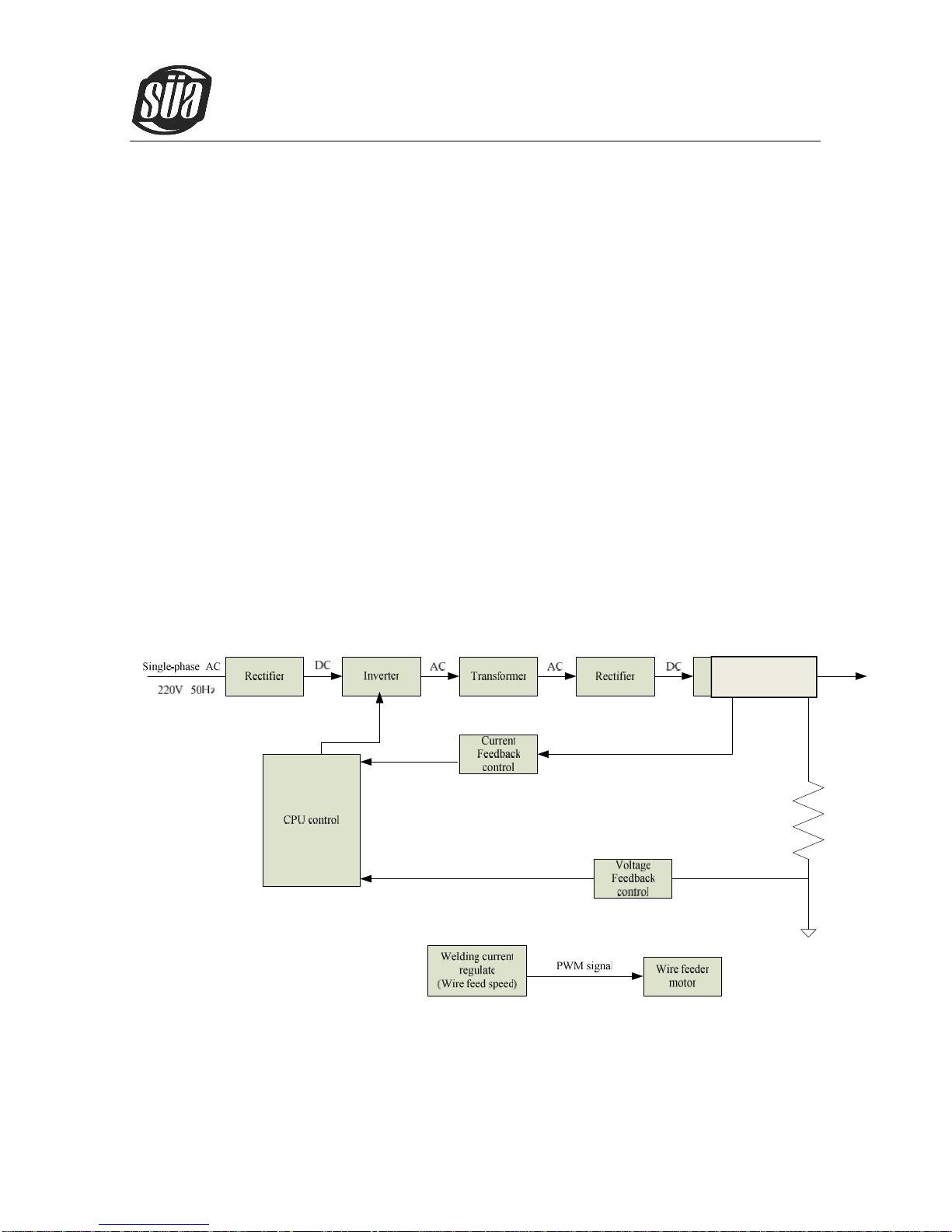
2.2 Working Principle
The working principle of MIG SERIES arc welding machine is shown as the following figure.
Single-phase 220V work frequency AC is rectified into DC(350V), then is converted to
medium frequency AC (about 40KHz) by inverter device (IGBT), after reducing voltage by
medium transformer (the main transformer) and rectifying by medium frequency rectifier (fast
recovery diodes), and is outputted by inductance filtering. The circuit adopts current feedback
control technology to insure current output stably when MMA or TIG. And adopts voltage
feedback control technology to insure voltage output stably when MIG. Meanwhile, the
welding current parameter can be adjusted continuously and infinitely to meet with the
requirements of welding craft.
Current sensor
ionMig 200 PFC
Copyright © Mundaka Welding & Gases, Inc.
8
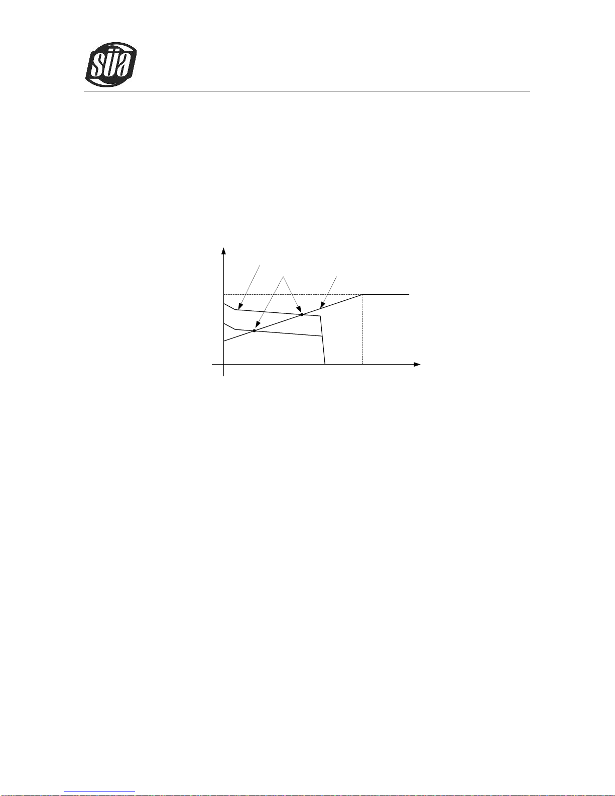
2.3 Volt-Ampere Characteristic
MIGSERIESweldingmachinehasanexcellentvolt-amperecharacteristic,whosegraphisshown
as the following figure. The relation between the rated loading voltage U2and welding current I2is as
follows: U2=14+0.05I2(V)
44
14
0 600 Io(A)
Uo(V)
Working point
Volt-ampere characteristic The relation between the rated loading
voltage and welding current
ionMig 200 PFC
Copyright © Mundaka Welding & Gases, Inc.
9
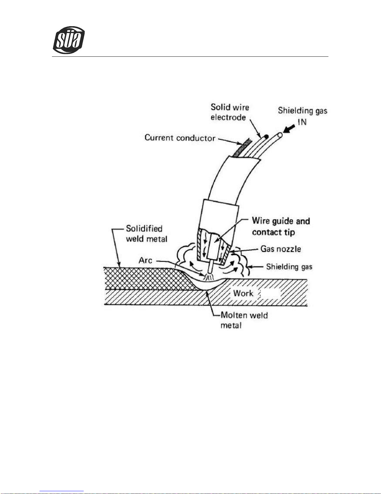
2.4 Principles of welding

ionMig 200 PFC
Copyright © Mundaka Welding & Gases, Inc.
10
3. Installation and Adjustment
3.1 Parameters
Model
Parameters
MultiMIG200PFC
MultiMIG250PFC
Input Voltage(V)
1-110±10%
1-220±10%
1-110±10%
1-220±10%
Input Current(A)
MIG 31.7
MMA 32
TIG 19
MIG 26
MMA 30
TIG 19.5
MIG 43
MMA 37
TIG 32
MIG 43
MMA 44
TIG 36
Input Power(KW)
MIG 3.4
MMA 3.5
TIG 2.1
MIG 26
MMA 30
TIG 19.5
MIG 4.7
MMA 4.0
TIG 3.5
MIG 9.4
MMA 9.6
TIG 7.9
Welding Current(A)
MIG 40-140
MMA 10-110
TIG 10-150
MIG 40-200
MMA 10-200
TIG 10-200
MIG 40-160
MMA 10-130
TIG 10-130
MIG 40-250
MMA 10-250
TIG 10-250
No-load Voltage(V)
66
66
66
66
Duty cycle(40℃)
MIG 140A30%
MMA 110A30%
TIG 150A40%
MIG 200A30%
MMA 200A25%
TIG 200A35%
MIG 160A35%
MMA 130A30%
TIG 140A35%
MIG 250A35%
MMA 250A30%
TIG 250A35%
Diameter(mm)
Fe :0.6、0.8、0.9、1.0 、1.2 Ss 0.8、0.9、1.0 、1.2
Protection class
IP23
Insulation class
H
Dimensions(mm)
550*214*395
635*240*430
Weight(Kg)
12.5
25
Note: The above parameters are subject to change with the improvement of
machines.
ionMig 200 PFC
Copyright © Mundaka Welding & Gases, Inc.
11
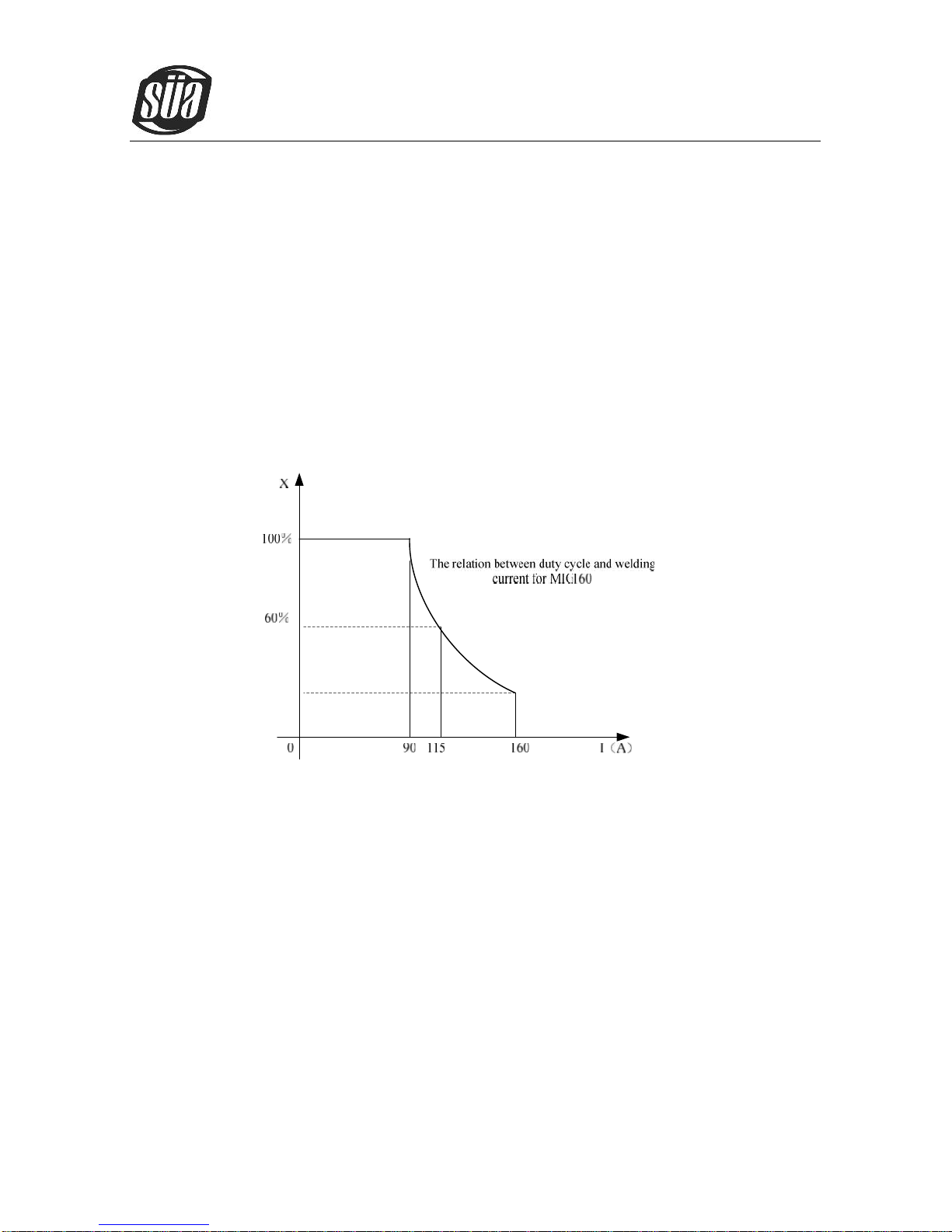
3.2 Duty cycle and Over-heat
The letter “X” stands for the duty cycle, which is defined as the proportion of the time that a
machine canworkcontinuouslywithinacertaintime(10minutes).The rateddutycycle means the
proportion of the time that a machine can work continuously within 10 minutes when it outputs the
rated welding current.
The relation between the duty cycle “X” and the output welding current “I” isshown as the right
figure.
If transformer is over-heat, the heat relay inside it will open and will output an instruction to
circuit board, cutAC relay andthe output welding current,and brighten the over-heat pilot lamp in
the front panel.At this time, the machine should be relaxed for 15 minutes to cool the fan. When
operating the machine again, the welding output current or the duty cycle should be reduced.
ionMig 200 PFC
Copyright © Mundaka Welding & Gases, Inc.
12
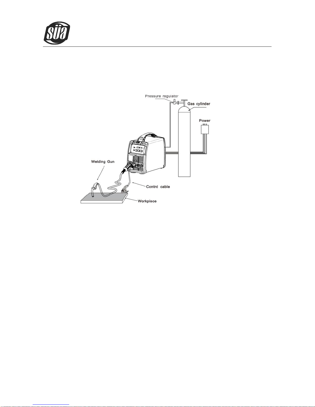
3.3 Equipment Connection
Operation Steps:
1. Connect the power source input cable of welding machine with the output port of air switch in
electric box on the spot.
2. Connect the cable plug of wire feeder to the positive output of welding machine.
3. Connect the control cable plug of wire feeder to the aero socket on the front board of welding
machine.
4. Connect the negative pole of welding machine to the work piece (base metal).
5. Connect the output pipe of gas cylinder to the input joint of gas valve on the wire feeder and
clamp it.
6. Insert the torch joint into theoutput of wire feeder unit and keep the wire aim atthe wire feeder
7. Connect the shielded gas pipe of torchwith the output of front panel on wire feeder.

ionMig 200 PFC
Copyright © Mundaka Welding & Gases, Inc.
13
8. Connect the control cable pin of torch with the two-lead aero socket of front panel on wire
feeder.
9. Notice that the wire diameter should be accordant with the wire wheel and torch tip and press
the wire properly with the handle.
3.4 Maintenance of MIG Gun mechanism
3.4.1 Dissection graphics for the MIG GUN
标准化
工艺
批准
日期
设计
制图
校对
审合
处数
标记 更改文件号 重量(g)
共页共
日期
签字
上海亿诺科技有限公司
零部件描述 参考编号 材料
公差选择范围
页
外形尺寸
ICT2098
描 述
图 号
序号 备 注
焊枪15/3米/弹性针/蓝色手柄 -------
上海市顾戴路2535弄99号3号楼2楼
16
图 号
序号
1
2
9
3
6
7
8
11
10
12
13
描 述 数量 备 注
12
34
7
11
1213
14
15
1617
ICS0063
ICU0003-08
ICZ6087
ICV0685
IHQ0070
IFT0874
IHJ0715
IHJ0782
14
IHJ0028
IHJ0645
IFT0063
IZT0071
1
1
1
1
3
1
1
1
1
1
1
1
18
17 送丝管锁紧螺母
带绝缘层送丝管0.6-0.8 3米 蓝色IIC0500
导电嘴 0.8/M6*25
喷嘴 D.12 14-15AK
螺丝 M4X6 UNI 6107
15AK 枪颈(包括六角适配器和塑料适配器)
MIG蓝色手柄
焊枪用开关 21.8mm
螺丝 D.3x10
电缆护套 12-16-25 MMQ
电缆支撑用球节 15AK
手柄锁紧环
二氧化碳欧式后把套
数量
1
1
19
18
10
95 6
8
塑料适配器
六角适配器
IZH0667
IHJ0030
5
4
1
15
ITB0059 欧式中央插头/弹性针 1
ICG6000
19 导电嘴扳手 1
IHJ0063 焊枪锁紧螺母/塑料螺纹 1
ICN0663 同轴电缆组/16mmq/3米 1
3.1 ICZ0087 15AK 枪颈 1
3.1

ionMig 200 PFC
Copyright © Mundaka Welding & Gases, Inc.
14
3.4.2 The parts list for the MIG GUN
NO.
Description
QTY.
Remark
1
Tip D.12 14-15AK
1
2
Electric nozzle 0.8/M6*25
1
3
15AK Goose gun neck(Hexangular adapter and Plastic adapter)
1
3.1
15AK Goose gun
1
4
Hexangular adapter
1
5
Plastic adapter
1
6
MIG blue handle
1
7
Torch Switch 21.8mm
1
8
Screw D.3*10
3
9
Handle locking ring
1
10
Cable fixing joint 15AK
1
11
Coaxial cable team /16mmq/3m
1
12
Cable thimble 12-16-25 MMQ
1
13
CO2Euro-rear thimble
1
14
Screw M4*6 UNI 6107
1
15
Torch locknut /plastic screw thread
1
16
Euro-main socket/flexibility pin
1
17
Feeding pipe locknut
1
18
Insulating feed pipe 0.6-0.8 3m, Blue
1
19
Spanner for the electric nozzle
1
3.4.3 The operation for the MIG GUN
1. Service the wire feed mechanism at least every time the reel is changed.
Check the wear of the feed roll groove and change the feed roll when necessary.
Clean the welding gun wire guide with compressed air.
2. Cleaning the wire guide
Pressure ofthefeedrollsremove metaldustfromthefiller wire’ssurface whichthenfinds its
way to the wire guide. If the wire guide is not cleaned, it gradually clogs up and causes wire
feed malfunctions. Clean the wire guide in the following manner:

ionMig 200 PFC
Copyright © Mundaka Welding & Gases, Inc.
15
Remove the welding gun’s gas nozzle, contact tip and contact tip’s adapter.
With a pneumatic pistol, blow compressed air through the wire guide.
Blow the wire feed mechanism and reel housing clean with compressed air.
Reattach the welding gun’s parts. Tighten the contact tip and contact tip’s adapter to spanner
tightness.
3. Changing the wire guide
If the wire guide is too worn or totally clogged, change it to a new one according to the following
instructions:
Open the mounting nut of the wire guide whichexposes the end of the wire guide.
Straighten the welding gun’s cable and withdraw the wire guide from the gun.
Push a new wire guide in to the gun. Make sure that the wire guide enters all the way into the
contact tip’s adapter and that there is an O-ring at themachine-end of the guide.
Tighten the wire guide in place with the mounting nut.
Cut the wire guide 2mm from the mounting nut andfile the sharp edges of the cut round.
Reattach the gun in place and tighten the parts to spanner tightness.

ionMig 200 PFC
Copyright © Mundaka Welding & Gases, Inc.
16
4. Operation
4.1 Layout for the front and rear panel

ionMig 200 PFC
Copyright © Mundaka Welding & Gases, Inc.
17
1. Choose weldingmode key:On TIGorMIG, Pressing thekey can choose 2Tor 4Tweldingmode.
2. Choose welding method key: Pressing the key can choose three function, MMA/TIG/MIG.
3. Welding current knob: Set the welding current.
4. Current display: Welding Current display when machine is working, Set current display before
welding. Unit:A.
5. Current LED:When the current LED is on, it display the actual output welding current(MIG).
6. Wire speed LED:You can use current setting knob to set the wire speed when the wire speed
LED is on (MIG).
7. Voltagedisplay:Weldingvoltagedisplaywhen machineisworking,Setvoltage displaywhenMIG
mode before welding. Unit:V.
8. Welding voltage/Down slope/Arc force knob: On MIG, when the program voltage can’t perfectly
match the welding current, the knob can adjust voltage On TIG, the knob can adjust the current
down time. On MMA, the knob can adjust the force current.
9. Power Led: Power led is lighted when open the machine.
10. Alarm Led: When the welder is over voltage, less voltage, over current or over heated, the alarm
pilot lamp will be on.
11. Wavecontrolknob:Controlsarccharacteristics,Determinestherateatwhichtheamperagerises
when a short circuit is produced.
12. TIG GAS Connect
13. MIG GUN Connect.
14. Output cathode:When MIG mode, this polarity must connect the work piece
15. TIG gun control connecter.

ionMig 200 PFC
Copyright © Mundaka Welding & Gases, Inc.
18
16. Output anode: When TIG mode, this polarity must connect the work piece
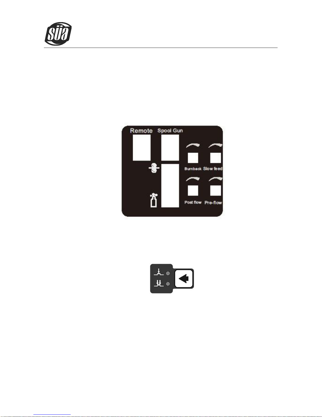
17. Remote Switch
18. Spool Gun Switch
19. Burn back knob
20. Slow feed knob
21. Manual wire switch & air check switch: up for manual wire and down forair check.
22. Post flow knob
23. Pre-flow knob
4.2 Welding operation
For example MULTIMIG 200
4.2.1 MIG mode operation:
1. Shielding Gas choice
1) When the wire material is Fe, the shielding gas is 80%Ar + 20%CO2 ;
2) When the wire material is Ss, the shielding gas is 98%Ar + 2%O2 ;
3) When the wire material isAl, the shielding gas is 100%Ar.
2. Welding state choice
1) Press the weld manner key, choose MIG manner and the MIG LED is lighted;
ionMig 200 PFC
Copyright © Mundaka Welding & Gases, Inc.
19
2) Spool Gun Switch turn off (down).
3) Manual wire switch & air check switch,Burn back adjust,Slow feed adjust, post flow
adjust, Pre-flow knob adjust;
4) Press the welding mode key, choose 2T or 4T;

ionMig 200 PFC
Copyright © Mundaka Welding & Gases, Inc.
20
5) Spool Gun Switch turn on (up):
3.Adjust Welding parameter
1) Different wire diameter, the minimum welding current is different;
2)Adjust the current knob, the corresponding welding voltage is changed automatically;
3) When the programmable welding voltage isn’t the perfect for the operator, the voltage can be
changed by adjusted the knob;
4) If the operator adjust the wave control knob, the arc characteristics can be controlled.
Table of contents
Other Sua Welding System manuals


