Sua ionMig 250 User manual

ionMig 250
Copyright © Mundaka Welding & Gases, Inc.
ionMig 250
INVERTER IBGT –MIG WELDING MACHINE
OPERATION MANUAL
IMPORTANT: Read this Owner’s Manual Completely before attempting to use this
equipment. Save this manual and keep it handy for quick reference. Pay particular
attention to the safety instructions we have provided for your protection. Contact your
distributor if you do not fully understand this manual.

ionMig 250
Copyright © Mundaka Welding & Gases, Inc.
2
CONTENT
1. SAFETY ...................................................................................................................................3
2. GENERAL DESCRIPTION.......................................................................................................5
3. CIRCUIT DIAGRAM.................................................................................................................6
4. MAIN PARAMETER.................................................................................................................7
5. PANEL INSTRUCTION ............................................................................................................8
5.1 Front panel instruction.........................................................................................................8
5.2 Back panel instruction .......................................................................................................10
5.3 Middle panel instruction .................................................................................................... 11
6. INSTALLATION & OPERATION ............................................................................................12
6.1 Input cable connection.......................................................................................................12
6.2.1 Arc welding installation...................................................................................................12
6.2.2 Sketch map of installation:..........................................................................................13
6.2.3 Operation .........................................................................................................................14
6.3.1 MIG welding installation..................................................................................................14
6.3.2 Sketch map of installation:..........................................................................................15
6.3.3 Operation:.....................................................................................................................15
6.4.1 No gas, self-protection welding installation:.................................................................16
6.4.2 Sketch map of installation:..........................................................................................17
6.4.3 Operation: ........................................................................................................................17
7. CAUTION ...............................................................................................................................18
7.1 Working Environment ........................................................................................................18
7.2 Good Ventilation .................................................................................................................18
7.3 Over-voltage is forbidden ..................................................................................................18
7. 4 Over-load is forbidden ......................................................................................................19
7. 5 Over-heating Protection....................................................................................................19
8. MAINTENANCE .....................................................................................................................19
9. TROUBLESHOOTING ...........................................................................................................20
ionMig 250
Copyright © Mundaka Welding & Gases, Inc.
3
1. SAFETY
Welding is dangerous, and may cause damage to you and others, so take good protection when welding.
For details, please refer to the operator safety guidelines in conformity with the accident prevention
requirements of the manufacturer.
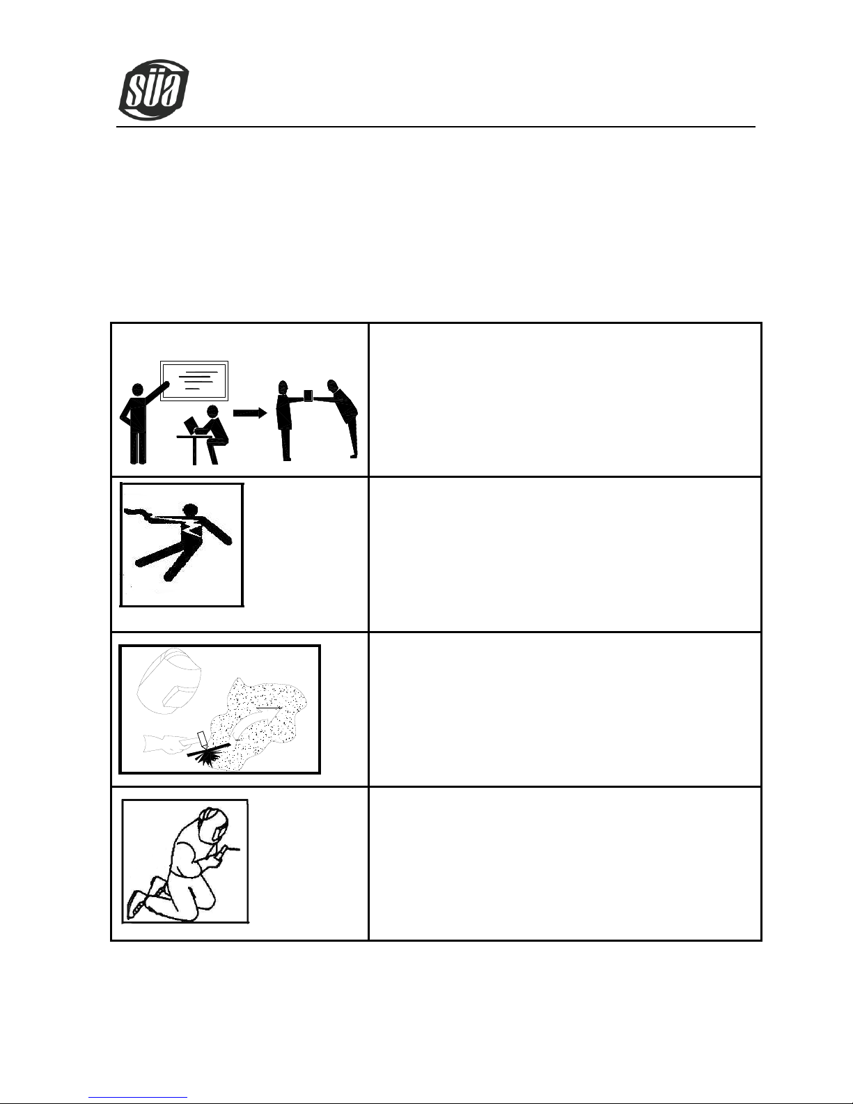
Professional training is needed before operating the
machine.
·Use labor protection welding supplies authorized by national
security supervision department.
·The operator must be special personnel with a valid "metal
welding (OFC) operations" operation certificate.
·Cut off power before maintenance or repair.
Electric shock—may lead to serious injury or even
death.
·Install grounding device according to the application criteria.
·Never touch the live parts when skin bared or wearing wet
gloves/clothes.
·Make sure that you are insulated from the ground and
workpiece.
·Make sure that your working position is safe.
Smoke& gas—may be harmful to health.
·Keep the head away smoke and gas to avoid inhalation of
exhaust gas from welding.
·Keep the working environment in good ventilation with
exhaust or ventilation equipment when welding.
Arc radiation—may damage eyes or burn skin.
·Wear Suitable welding masks and protective clothing to
protect your eyes and body.
·Use suitable masks or screens to protect spectators from
harm.
ionMig 250
Copyright © Mundaka Welding & Gases, Inc.
4
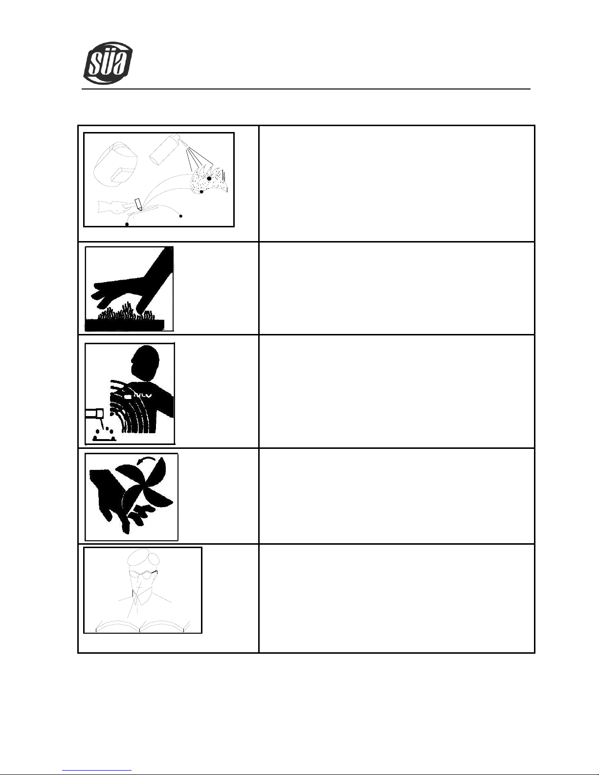
Improper operation may cause fire or explosion.
·Welding sparks may result in a fire, so please make sure no
combustible materials nearby and pay attention to fire
safety.
·Have a fire extinguisher nearby, and have a trained person to
use it.
·Airtight container welding is forbidden
·Pipe thaw with this machine is forbidden.
Hot workpiece may cause severe scalding.
·Don’t contact hot workpiece with bare hands.
·Cooling is needed during continuous use of the welding
torch.
Magnetic fields affect cardiac pacemaker.
·Pacemaker users should be away from the welding spot
before medical consultation.
Moving parts may lead to personal injury.
·Keep yourself away from moving parts such as fan.
·All doors, panels, covers and other protective devices should
be closed and in place.
Machine fault—seek professional help when
encountering any difficulties.
·Consult the relevant contents of this manual If you encounter
any difficulties in installation and operation.
·Contact the service center of your supplier to seek
professional help If you still cannot fully understand after
reading the manual or still cannot solve the problem
according to the manual.

ionMig 250
Copyright © Mundaka Welding & Gases, Inc.
5
2. GENERAL DESCRIPTION
Triple function machine that contain MIG welding, arc welding and no gas self-protection
welding.
Use IGBT with unique control method as inverter power device for increase the reliability
of welding machine.
The duty cycle is so high that can weld long time.
Closed loop feedback control, constant voltage output, fit for wide voltage range (±15%)
Adjustable welding voltage and current, excellent welding characteristics.
MIG welding use the unique welding dynamic characteristic control circuit, stable welding
arc, and little splash, beautiful shaping, high welding efficiency.
Function of removing the molten ball after welding available, high no-load, slow wire
feeding, high successful rate of arc starting.
The current of arc welding is stable, lift arc performance is excellent, and any model
welding rod is available.
Inverter frequency is 20 KHz, greatly reducing the volume and weight of the welder.
Great reduction in metal loss obviously enhances the welding efficiency and energy
saving effect.
Switching frequency is beyond audio range, which almost eliminates noise pollution.

ionMig 250
Copyright © Mundaka Welding & Gases, Inc.
6
3. CIRCUIT DIAGRAM
A

ionMig 250
Copyright © Mundaka Welding & Gases, Inc.
7
4. MAIN PARAMETER
TYPE
MIG200
MIG250
MIG200MY
MIG250MY
Input voltage (V)
Single-phase
AC230V±15%,50/60Hz
3-phase
AC410V±15%,50/60Hz
Rated input current (A)
33
45
16
22
Rated power supply capacity
(KVA)
7.5
10.4
6.6
9.2
Recommended fuse capacity
(A)
60
70
70
70
Arc welding current adjustment
range (A)
10~200
10~250
10~200
10~250
Gas protection welding current
adjustment range (A)
25~200
25~250
25~200
25~250
Gas protection welding voltage
adjustment range (V)
11~27
11~29
11~27
11~29
No-load voltage (V)
52
54
52
54
Feed speed adjustment range
(m/min)
1.5~16
1.5~16
1.5~16
1.5~16
Welding wire diameter
applicable (mm)
0.6/0.8/0.9 /1.0
0.6/0.8/0.9 /1.0
0.6/0.8/0.9 /1.0
0.6/0.8/0.9 /1.0
Rated duty cycle 40 °C
35% @ 250 Amp
Efficiency (%)
85
85
85
85
Power factor
0.75
0.75
0.85
0.85
Protection class
IP21S
Insulation class
F
Size (mm)
880×296×616
880×296×616
880×296×616
880×296×616
Weight (Kg)
75
77
75
77
ionMig 250
Copyright © Mundaka Welding & Gases, Inc.
8
5. PANEL INSTRUCTION
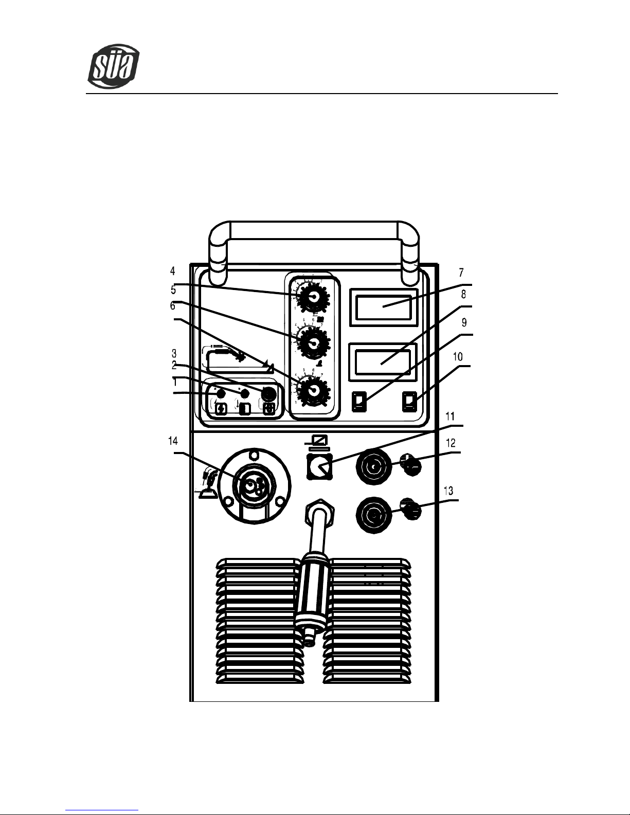
5.1 Front panel instruction
MIG 250
ARC
MIG
Pull
Push

ionMig 250
Copyright © Mundaka Welding & Gases, Inc.
9
(1) Power LED
(2) Over-heating LED
(3) Wire feeding switch
(4) Arc welding current adjustment
(5) Gas protection welding voltage adjustment
(6) The wire feeding speed of gas protection welding adjustment
(7) Voltmeter
(8) Ammeter
(9) Function switch of MIG welding and arc welding
(10)Function switch of wire feeding torch
(11)Socket of wire feeding torch control cable
(12) “+”output terminal
(13) “-”output terminal
(14) Euro-style welding torch connection of MIG welding
ionMig 250
Copyright © Mundaka Welding & Gases, Inc.
10
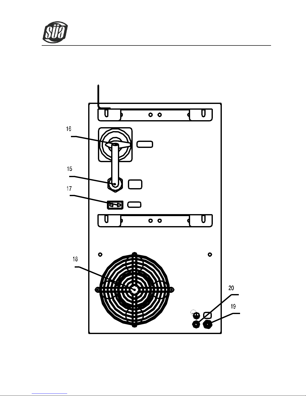
5.2 Back panel instruction
ionMig 250
Copyright © Mundaka Welding & Gases, Inc.
11
(15) Input power cable
(16) Power switch
(17) Power socket
(18) Fan
(19) Gas hose connector
(20) Grounding screw
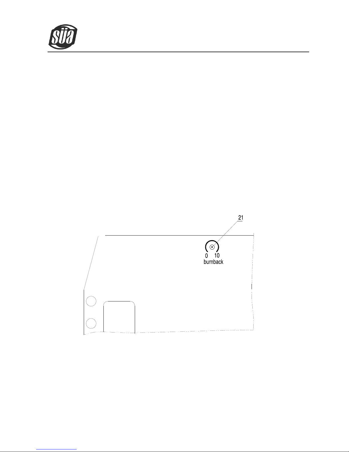
5.3 Middle panel instruction
(21)Burn back time adjustment

ionMig 250
Copyright © Mundaka Welding & Gases, Inc.
12
6. INSTALLATION & OPERATION
Note: ·Please install the machine strictly according to the following steps.
·Electric connection operation should be after turning off the power supply switch of the
switch box.
·The protection class of this machine is IP21S, so avoid using it in rain.
6.1 Input cable connection
A. Every machine has input cable, connecting them with the corresponding voltage class according to
the input voltage of welding machines. Please don’t connect with wrong voltage class. (Notice: when
connection the welding machine should be earthed reliably.)
B. The input cable should be connected well with the corresponding power supply connection pole or
socket, avoid oxidation.
C. Check if the input voltage within the fluctuation range.
6.2.1 Arc welding installation
A. Every welding machine matches two plugs. Insert the plug into the socket at the bottom of the front
panel, and tighten it, ensure contact good. Otherwise if the working time is long and the working
current is big, it will burn the pin and socket. Please treat it seriously.
B. Insert the welding clamp cable into the “+” socket at the bottom of the front panel, workpiece connect
with the“-”.
C. It should be pay attention to the wire’s polarity. Generally, DC welding machines have two connection
methods: positive connection and negative connection. Positive connection: insert the welding clamp
into the “-” and the workpiece into the “+”; Negative connection: insert the workpiece into the “-”
ionMig 250
Copyright © Mundaka Welding & Gases, Inc.
13
and the welding clamp into the “+”. Choose which connection method when welding should according
to workpiece metal and craft requirements. If select inappropriately, the electric arc will not stable,
also have some spatter, stick the welding rod and so on. In this case, you can replace the plug
conveniently to change the polarity.
D. If the distance between workpiece and welder is too far (50-100m), the welding cable and earth cable
are long, in this case, the cross-sectional area of wire should big enough to reduce the cable voltage
falling.
6.2.2 Sketch map of installation:
SWITCHING BOX

ionMig 250
Copyright © Mundaka Welding & Gases, Inc.
14
6.2.3 Operation
A. After installing the machine according to the above steps, set the power switch of the back panel in
the “on” position, and the machine will be started. The power supply LED lights, the fan begins to turn.
B. Select the arc welding through the function switch at the bottom of front panel. According to the
thickness of workpiece, adjust the “welding current adjustment knob”, let the welding performance
reach to the requirements.
C. General speaking, welding rod corresponding to the welding current as below:
Φ2.5:70-100A; Φ3.2 : 110-160A; Φ4.0 : 170-220A; Φ5.0 : 230-280A
6.3.1 MIG welding installation
A. Plug the welding torch into the “ ” output socket at the front panel of the machine, and tighten it.
Meanwhile, let the welding wire penetrate into the torch by hand.
B. Insert the cable plug with earth clamp into the “-” socket at the front panel of the machine, and tighten
it clockwise.
C. Insert the quick plug of wire feeder into the “+” socket at the front panel of the machine, and tighten it
clockwise.
D. Fix the wire reel to the wire feeding rack axis, matching the groove position of the wire feeding wheel
with the contact tip of the welding torch and the welding wire diameter.
Meanwhile, loosen the strut bracing, and make the wire into the glove of the wire feed wheel, press
the wire tightly, but not too tight, and then thread the wire into the torch. Press the” wire feeding”
button to feed the wire out of the welding torch.
E. Connect the air inlet at the back panel of machine to the gas bottle with gas reduced pressure
flowmeter by gas hose.

ionMig 250
Copyright © Mundaka Welding & Gases, Inc.
15
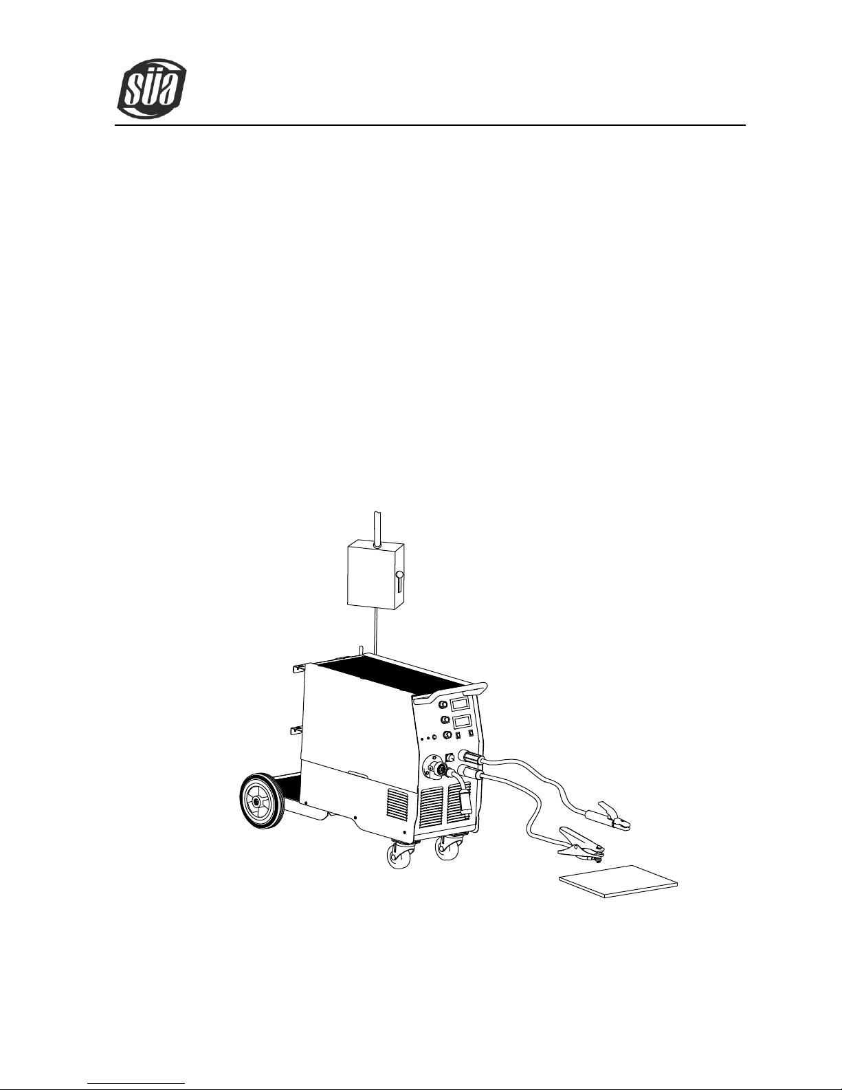
6.3.2 Sketch map of installation:
GAS HOSE
SWITCHING BOX
6.3.3 Operation:
A. After installing the machine according to the above steps, set the power switch of the back panel in
the “on” position, and the power supply LED lights, the fan begins to turn. Open the gas bottle and
adjust the flow meter on the gas meter to get the desired gas flow volume.
B. Set the function switch of the front panel in the gas protection welding status, and adjust the gas

ionMig 250
Copyright © Mundaka Welding & Gases, Inc.
16
protection welding voltage and wire feeding speed knobs, opt the suitable welding voltage and
current.
C. Press the welding torch switch to start working.
D. According to the requirements, adjust the burn back potentiometer in the middle panel to change the
length of welding wire extend contact tip after welding.
E. The gas will be cut off 1s after the arc stops.
6.4.1 No gas, self-protection welding installation:
A. Plug the welding torch into the “ ” output socket at the front panel of the machine, and tighten it.
Meanwhile, let the welding wire penetrate into the torch by hand.
B. Insert the cable plug with earth clamp into the “+” socket at the front panel of the machine, and tighten
it clockwise.
C. Insert the handle wire quick plug of wire feeder into the “-” socket at the front panel of the machine,
and tighten it clockwise.
D. Fix the wire reel to the wire feeding rack axis, matching the groove position of the wire feeding wheel
with the contact tip of the welding torch and the welding wire diameter.
Meanwhile, loosen the strut bracing, and make the wire into the glove of the wire feed wheel, press
the wire tightly, but not too tight, and then thread the wire into the torch. Press the” wire feeding”
button to feed the wire out of the welding torch.

ionMig 250
Copyright © Mundaka Welding & Gases, Inc.
17
6.4.2 Sketch map of installation:
SWITCHING BOX
6.4.3 Operation:
A. After installing the machine according to the above steps, set the power switch of the back panel in
the “on” position, and the power supply LED lights, the fan begins to turn.
B. Set the function switch of the front panel in the gas protection welding status, and adjust the gas
protection welding voltage and wire feeding speed knobs, opt the suitable welding voltage and
current.

ionMig 250
Copyright © Mundaka Welding & Gases, Inc.
18
C. According to the requirements, adjust the burn back potentiometer in the middle panel to change the
length of welding wire extend contact tip after welding.
D. Press the welding torch switch to start working.
7. CAUTION
7.1 Working Environment
A. Welding should be carried out in a relatively dry environment with its humidity of 90% or less.
B. The temperature of the working environment should be within -10C to 40C.
C. Avoid welding in the open air unless sheltered from sunlight and rain, and never let rain or water
filters the machine.
D. Avoid welding in dusty area or environment with corrosive chemical gas.
E. Avoid gas shielded arc welding in environment with strong airflow.
7.2 Good Ventilation
This welding machine has so big welding current when working that nature ventilation cannot meet the
cooling demand, while the inner fan enables the machine to work steadily by its effective cooling.
Operator should make sure the louvers are uncovered and unblocked. The minimum distance between
the machine and nearby objects should be 30cm. Good ventilation is of critical importance to the normal
performance and service life of the machine.
7.3 Over-voltage is forbidden
The power supply voltage has been showed in the main parameter table. General speaking, the voltage
in the welding machine will compensate the circuit automatically, for ensuring the welding current in the
permitted range. If the voltage exceeds the permitted limit, the machine will be damaged. The users
should know this situation, and take the corresponding measures. So pay attention to the changes in

ionMig 250
Copyright © Mundaka Welding & Gases, Inc.
19
voltage. Once over-voltage occurs, stop welding and switch off the power.
7. 4 Over-load is forbidden
The users should check the max permitted load current at any time (relatively the fixed duty cycle). The
welding current can’t exceed the max permitted load current. Over-loaded current will cut the welding
machine use life remarkably, and maybe burn the welding machine.
7. 5 Over-heating Protection
Over-heating protection appears while the machine is of overload status because of continuous welding
for a long time, and a sudden halt of welding occurs. In this case, it is unnecessary to restart the
machine, but just wait for the over-heating LED to go out, and welding can be recovered.
8. MAINTENANCE
WARNING: The following operation requires sufficient professional knowledge on
electric aspect and comprehensive security knowledge. Operators should be holders of
valid qualification certificates which can prove their skills and knowledge. Make sure the
input cable of the machine is cut off from the electricity before uncovering the welding
machine.
A. Check periodically whether inner circuit connection is ok (esp. plugs). Tighten the loose connection. If
there is oxidization, remove it with sandpaper and then reconnect.
B. Keep hands, hair and tools away from the moving parts such as the fan to avoid personal injury or
machine damage.
C. Clean the dust periodically with dry and clean compressed air. If welding in environment with heavy
smoke and pollution, the machine should be cleaned daily. The pressure of compressed air should

ionMig 250
Copyright © Mundaka Welding & Gases, Inc.
20
be at a proper lever lest the small parts inside the machine be damaged.
D. Avoid rain, water and vapor filters the machine. If there is, dry it and check the insulation with a
megger (including that between the connections and that between the connection and the case).
Only when there is no abnormal phenomena can welding be continued.
E. Check periodically whether the insulation skin of all cables are perfect. If there is any dilapidation,
wrap it or replace it.
F. Check periodically whether the gas hose has any cracks. If any, get them replaced.
G. Put the machine into the original packing in dry location if it is not to be used for a long time.
9. TROUBLESHOOTING
WARNING: The following operation requires sufficient professional knowledge on
electric aspect and comprehensive security knowledge. Operators should be
holders of valid qualification certificates which can prove their skills and
knowledge. Make sure the input cable of the machine is cut off from the
electricity before uncovering the welding machine.
Common Malfunction Analysis and Solution
Malfunction phenomena
Solution
1. The overheating protection
LED turns on.
A. Check the welding current and welding time. Operate according to the
requirement referring to the instruction manual.
B. Check the fan’s running status when welding. If the fan does not work,
check if there is a power supply of 230V: If the power supply is normal,
Table of contents
Other Sua Welding System manuals


Popular Welding System manuals by other brands

Miller
Miller Augmented Arc owner's manual

Lincoln Electric
Lincoln Electric SPEEDTEC 405S Operator's manual

ArcOne
ArcOne Inverter Power Sources User instruction manual

Miller Weldmaster
Miller Weldmaster Triad Extreme manual

K.C.D. STUDWELDING
K.C.D. STUDWELDING CD1000 instruction manual

Draper
Draper MPW190 instructions


