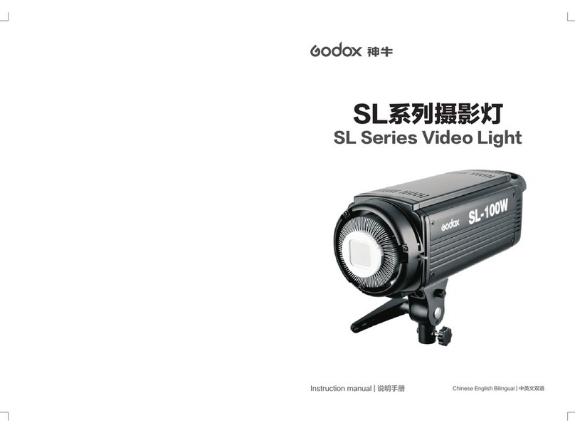
SubSurface Instruments AML+ User manual

SUBSURFACE
INSTRUMENTS, INC.
AML+™
OPERATOR’S
MANUAL
www.ssilocators.com

INSPECTION OF THE AML+
DO NOT open the housing of this unit.
Doing so will damage the transmission
and receiving antennas. There are no
user serviceable parts inside. Opening
the sealed case will void the warranty.
If maintenance, tuning, or repair
becomes necessary contact:
SubSurface Instruments, Inc.
email: info@ssilocators.com
Telephone: 920-347-1788 or
Or by mail:
SubSurface Instruments, Inc.
1230 Flightway Drive
De Pere, WI 54115 USA
AML SAFETY INFO
READ & OBSERVE ALL INSTRUCTIONS
Save these instructions for future reference.
2
Proudly Made in the USA

Do not direct the laser beam at
people or animals. Do not stare
into the laser beam. The AML+
produces Laser Class II/2M
laser radiation according to IEC
60825-1.
Looking directly into the
laser beam - especially with
optical instruments such as
binoculars or magniers - can
permanently damage the eye.
This is a professional tool, not
a toy. It should not be used by
children.
OPERATION
Only use this equipment for
the purpose specied by the
manufacturer. Any misuse may
void the warranty.
READ & OBSERVE SAFETY WARNINGS
Save these instructions for future reference.
D
F
I
E
P
English
German
French
Italian
Spanish
Portuguese
3

How the AML+ Works
The unit contains an internal control
circuit board, and an antenna board
that controls the center transmitter
and independent left and right signal
receivers.
A powerful 2.45 GHz ground-
penetrating, ultra-high frequency radio
signal locates density differences by
transmitting inverted conical shaped
UHF signals into the ground.
The unit locates objects by analyzing
differences in subsurface material
densities. Man-made objects or
geometries with a straight edge create
a change in conductivity, density and/
or permeability from surrounding
materials. This causes a distortion in
the return signal detected by the UHF
receivers on the sides of the AML+,
and is interpreted by the advanced
microprocessor circuit board
technology.
OPERATING INSTRUCTIONS
User Reference - Scanning QR Codes
AML+ reference videos and instructions can be accessed from
your smart phone using a standard QR code app. QR codes can
be found and scanned from the blade side (or backside) of your
AML+ unit. For more information on how to download and/or use a
QR code app, visit the app store on your smart phone. Reference
materials
can also be accessed by visiting the SSI website at
ssilocators.com.
4

FCC
This equipment was tested and
found to comply with the lim-
its for a Class A digital device,
pursuant to Part 15 of the FCC
rules. These limits are designed
to provide reasonable protec-
tion against harmful interference
when the equipment is operated
in a commercial environment.
This equipment generates,
uses, and can radiate radio
frequency energy.
IC (Industrie Canada)
Canadian Compliance State-
ment: Complies with the
Canadian ICES-003 Class B
specications. Cet appareil
numérique de la Classe B est
conforme à la norme NMB-003
du Canada.
This device complies with RSS
210 of Industry Canada. This
Class B device meets all the
requirements of the Canadian
interference-causing equip-
ment regulations. Cet appar-
eil numérique de la Classe B
respecte toutes les exigences
du Règlement sur le matériel
brouilleur du Canada.
FCC/IC/CE STATEMENTS
CE Approved
(European Countries)
European Community
Compliance Statement: The
equipment complies with the
RF Exposure Requirement
1999/519/EC, Council
Recommendation of 12 July
1999 on the limitation of
exposure of the general public
to electromagnetic elds (0–
300 GHz). This wireless device
complies with the R&TTE
Directive.
5

CONTROLS AND FUNCTIONS
1
2
3
4
5
6
7
8
10
9
Backside view of unit
11
6

1) EASY BATTERY ACCESS
The AML+ is powered by either a convenient 9-volt battery
system, or by a rechargeable Lithium battery pack.
2) ERGONOMIC HANDLE
The ergonomically designed handle allows the operator to hold the
AML+ for extended periods of time in all weather conditions.
3) POWER & 9-POSITION SENSITIVITY SWITCH
The POWER & SENSITIVITY switch controls the unit’s power
supply and sensitivity adjustment. Turn the unit ON, and choose the
appropriate sensitivity level depending on surface and/or soil type.
4) RIGHT SIDE & LEFT SIDE TARGET INDICATORS
LED target indicators identify when an object has been located,
and when the object is parallel with the AML+. Audio and laser
target indicators work in unison with the right and left LEDs to alert
the operator of an object’s presence, and to place its location.
5) LED POWER INDICATOR
The power indicator LED emits a bright green light when the unit is
ON. This LED also serves as the battery life indicator and ashes
green and red when battery power is low.
6) LIGHTWEIGHT, DURABLE CONSTRUCTION
The electronic circuitry of this unit is housed in a tough, water-
resistant, high-impact ABS enclosure. This enclosure protects the
sensitive electronic components. It does not protect the unit from
abuse or careless misuse. Treat this unit as a professional tool.
Keep it stored in the foam-insulated case when not in use.
7) GROUND-PENETRATING, ULTRA-HIGH FREQUENCY
(UHF) RADIO TRANSMITTER
An UHF transmitter delivers the intensity of the UHF signal as it is
aimed at its intended target.
7

8) LASER TARGET INDICATOR
A red laser indicator identies the target position on the ground
when an object has been detected; and an audible signal is
emitted.
9) ULTRA-HIGH RADIO FREQUENCY RECEIVERS
The receiver captures the returning UHF reection with antennas
on both ends of the unit. Positioning the unit parallel to an object’s
edge will activate the receiver’s antenna and illuminate both LED
lights, the laser target indicator, and activate an audio signal. 10
- HEAD PHONE JACK-PORT
10) HEAD PHONE JACK-PORT
Insert headphone jack into the headphone port for operation in
noisy environments if necessary.
11) USB PORT
The USB Port has several functions such as connecting the
auxiliary external lithium battery supply to the USB Port for
extended power, and for uploading or downloading diagnostic
information.
The lithium battery pack will provide a minimum of 20 hours of
continuous usage before needing to be re-charged. There are
several USB ports on the battery pack that can be used to power
additional pieces of equipment such as a cellphone or any other
device that requires a USB power supply. The battery pack can
be placed in any suitable holder or simply carried in the operator’s
pocket to power the AML+ and recharge a cellphone or other USB
powered device at the same time.
8

USING THE AML+
Operation of the AML+ is technique
sensitive. We advise that you practice
on a known buried object like a culvert
pipe or other partially exposed objects.
Once the principals of operation are
understood, acquiring a technique is
relatively simple with a little practice.
Factory training is available and highly
recommended.
The depth of the AML+ transmission
signal varies with material substrates.
The more dense the material, the
further the signal travels. This unit can
be used in various substrates such
as water, snow, red-clay, and does
not have the substrate restrictions of
ground penetrating (GPR) radar.
The AML+ has nine sensitivity
settings, with setting 9 being the
strongest (see gure 9-1). However,
the density of the material will
inuence the depth of the transmitted
signal. The transmission signal will
penetrate deeper through highly
reective materials such as concrete,
clay, asphalt, or highly compacted
soil (see gure 9-2); and, less deep
in sand, granular soil, or recently
backlled soil that tends to absorb
some of the return signal strength
(see gure 9-3).
IMPORTANT: The AML+ is water-
resistant, not water-proof. Cover
the unit with a clear plastic bag if
operating in wet weather conditions.
1
2
3
Note: Signals travel further in more
dense and highly reective materials.
Note: Level 9 provides the highest
sensitivity setting, 0 the lowest
sensitivity setting.
Figure 9-2 Figure 9-3
FIGURE 9-1
9

With the AML+ in parallel with the pipe
or underground object, you can now
scan the entire length of the object’s
edge. As an alternative, utilize the “W”
method of scanning by sweeping the
area in a back-and-forth “W” motion,
marking the object’s location and
direction as it is tracked.
Once the left or right target indicator is
activated, keep that side still and rotate
the AML+ in parallel with the subsur-
face object. Both the left and right LED
target indicators will light simultaneous-
ly and an audio sound will emit when
the unit is in parallel and in alignment
with the object.
2
Locating an Object with the AML
Grip the AML+ by the handle with the
ngers rmly placed along the nger
knurls. Do not hold the unit above the
knurls as it will produce false readings.
Hold the handle parallel to the ground
at waist level and 18 to 24 inches out
in front of the body. The blade of the
unit is designed with a 10º degree
outward projection to help eliminate
false readings from interference with
the operator’s feet (see Figure 10-1).
When an object is detected, the left
and right LED target indicators will
illuminate, an audio tone will sound
and the laser indicator will activate
marking your target. Lower the
sensitivity level to the lowest setting
that will still identify the object. This will
prevent most irrelevant positives from
being identied. Continue to scan the
target using one of several methods:
1) Straight line scanning by following
one edge of the pipe.
2) Holding the unit level and scanning
the area with a slow and deliberate
back and forth “W” morning.
Note: See the back of the AML+ for
QR Codes referencing additional user
instructions and videos.
Scan to view
training videos.
Figure 10-1
10

Marking the Exact Location of an
Object with the AML+
Remember that the 10º forward
projection of the blade will make the
object appear closer than it actually is
(see gure 11-1). Once the object is
found, pivot the handle of the AML+
upward until the blade (or bottom of
the AML+) is perpendicular to the
ground and directly above the area of
the signal (see gure 11-2). You can
now scan the ground in parallel for the
entire length of the object, identifying
its diameter or width, location and run
direction as you track the object.
Note: Read the Safety Notes section
(pages 3-4) before operating your
AML+.
11
10°
Figure 11-2
Locating Position:
Tilt the handle forward 10º when
locating the exact edge of an object.
10°
Figure 11-1
Searching Position:
Objects are further than they appear
when in the searching position.

Determining depth with the AML+
Once you have located the PVC pipe
or underground object, nd its center
and mark its position on the ground, tilt
the handle of the unit downward until
the blade is at 45º, (gure 12-1) and
walk backwards until you nd the top
of the pipe. Make a mark where the
laser indicator is located on the ground.
Measure the distance between both of the
marked points, this will be the depth at
where the PVC pipe is located.
10°
Depth = D
Ground Level
Subsurface Pipe
or Object
D = 10’
45º45º
1
1. Determine pipe’s center & mark the ground
2. Tilt the AML to a 45º angle*
3. Start walking backwards until you find the pipe again
- Make sure you located the pipe by scanning its edge 3’ to the right or left -
4. Mark the spot on the ground
5. The distance between both points is the depth of the pipe
1
2
3
4
5
2
3
4
5
* On the AML+ your can use a level application in your smart phone.
Useful Tip: if you tilt the handle downward until the 3rd nub from the battery cap is aligned
to the blade tip and they are parallel to the ground the blade will be at 45º.
12
Figure 12-1
45º
Useful Tip: if you tilt the handle downward
until the 3rd nub from the battery cap is
aligned to the blade tip and they are parallel
to the ground the blade will be at 45º
Parallel to the Ground
3rd. Nub

To Replace Batteries in Your AML+ Unit:
1. Unscrew the battery access cap and remove the
battery sleeve.
2. Individually, lift each battery out of the sleeve,
turn it 180 degrees and remove used battery.
3. Install new battery in the battery sleeve and re-
position by turning 180 degrees into the sleeve.
Use caution when handling the wiring harness.
4. Reinsert the battery sleeve into the handle,
silver lead end rst.
5. Replace battery access cap.
Note: One battery sleeve is included with each unit. Each battery sleeve uses
three (3) 9-volt industrial grade alkaline batteries. For best results and longer
battery life use only industrial grade 9-volt batteries. Additional or replacement
BATTERY REPLACEMENT
Easy Battery
Access Cap
Battery Pack
(Houses (3) 9-Volt
Batteries)
13

TECHNICAL SPECIFICATIONS
PRODUCT INFORMATION
Physical Dimensions
• Height................11” ............27.9cm
• Length ...............14” ............35.6cm
• Width .................6” ..............15.2cm
•
Weight ...............2 lbs .......0.90kg
Typical Operating Range
• Temperature: 0°F to 120°F (-17°C to 48°C)
Power Specications
Estimated Battery Life:
• (3) 9-Volt Industrial Strength Alkaline
Provides up to 7 hours of continuous operation at full power,
or 40 hours at average industry usage.
• Lithium Rechargeable Battery Pack
Provides over 20 hours of continuous usage and cellphone
recharging, or over 150 hours of use at average industry usage.
Shipping Dimensions
•
Cube..........20”l x 17”w x 8”h....... 50.8cm x 43.18cm x 20.32cm
•
Weight .......17lbs........................ 7.7kg
Includes
• (1) AML+ Unit
• (1) Battery Pack (Housing [3] 9-Volt Batteries)
• (1) Lithium Rechargeable Battery Pack with Battery Charger
and Cables
• (1) Headphones
• (1) Waterproof Foam-Insulated Hard Case
• (1) Operator’s Manual
• (1) Training Video Disc & Operator’s Manual File
14

AML+ Tiny BootLoader
This utility is used to install AML+ rmware
updates.
INSTALL SOFTWARE TO YOUR COMPUTER
Download Tiny BootLoader File
1. Download SSI Tiny BootLoader Utility from
the SSI web site at http://www.ssilocators.
com/specialty-products/all-materials-locator-
plus-series/, found on the Downloads tab
on the SSI website. Save the le to the
Downloads folder in your computer.
2. Go to the Downloads folder and extract
the le from the compressed le. If your
Operating System doesn’t have compress
software, you can go to http://www.winzip.
com/win/en/downwz.html to download a free
version.
3. Move the tinybldWinBeta.exe le to the
desktop, for easy access.
4. This is a very simple application, once you
have the le on your desktop, it is ready for
use.
Note: After completing the rmware update
process, your unit will need to be recalibrated,
use the AML+ Customer Utility to calibrate the
AML+ and to run diagnostics requested by the
manufacturer.
Updating the Firmware on the AML+
1. Connect the AML+ to your computer with the
supplied USB mini cable. Turn on the AML+;
if this is the rst time you connect your unit
to the computer, an automatic notications
will display: “New hardware has been
detected” and “Installing new device driver”.
When your operating system completes
its automatic driver installation, you will be
ready to proceed to the transfer process.
APPENDIX (FIRMWARE UPDATE)
PIC
tinybldWin...
Figure 15-2
Figure 15-3
Figure 15-1
15

Note: the computer will recognize this unit when connecting in future uses.
You can obtain the latest rmware updates by contacting Subsurface Instruments
folder to store the “*.HEX” (rmware update) le you receive from SSI.
APPENDIX
Figure 16-1
2. Click on the icon to run the
application.
3. The tiny bootloader screen will
display, (Figure 16-1).
4. The computer will automatically
recognize the Comm Port the AML+
is connected. The port # will
appear in the left panel of the screen.
5. Select your le source by clicking
on “Browse” button, select latest
rmware le and click “OK”
6. Go over the conguration settings in
all tabs, compare the values with the
values in page 17, make sure they
match.
7. On the left panel, click “Write Flash”.
This will start the transfer process
8. Upon completion, the screen will
display a string of values and
commands (Figure 17-4).
9. Your AML+ is now updated with the
latest rmware and needs to be
recalibrated.
Exit software.
1
2
1
2
16

APPENDIX
Figure 17-4
Figure 17-3
Figure 17-2
Figure 17-1
Terminal
Comm Port Speed: 9600
Tx/Transmitter: Char\
Rx/Reciever: Char - dump.bin
Options
ID code: C1h - Normal
Reset: “Active” RTS, DTR ON
Codes to send rst: 24h 49h
Search Delay: 7
Timeout(ms): 300
Search for COMs: “Active”
TermOpt
Graphic 2 reference: 128
Xaxis compression: 1
Click “Write Flash” to start
Upon completion a message
“WRITE OK” will display.
17

AML+ CUSTOMER UTILITY
The AML+ Customer Utility is used to calibrate
and run diagnostics on your AML+ unit.
INSTALL SOFTWARE TO YOUR COMPUTER
Download AML+ Customer Utility
1. Download AML+ Customer Utility from the
SSI web site at http://www.ssilocators.com/
specialty-products/all-materials-locator-plus-
series/, found under the Downloads Tab.
Save the le to your Downloads folder in your
computer.
2. Go to your downloads folder and extract
the le from the compressed le to access
SETUP-AML-PLUS-CAL-V1r3.exe If your
Operating System doesn’t have a compress
software, you can go to http://www.winzip.
com/win/en/downwz.html to download a free
version.
3. Double click the SETUP-AML-PLUS-CAL-V1r3.
exe and follow the instructions on the screen.
4. The Installation will create a shortcut on your
computer’s desktop for quick access to the
calibration process in the future.
Note: The calibration process must be
performed outdoors, with the AML+ plugged
into the computer and pointing to an
unobstructed sky. We suggest performing this
process with a portable computer or have a
USB extender cord.
RUNNING THE AUTOCALIBRATION
1. Click on the AML+ Cal V1.3 Icon
2. The utility will run a diagnostic of the AML+ and
display it on the screen,
APPENDIX (AML+ UTILITY APP)
AML+ CAL
V1.3
Figure 18-1
Figure 18-2
Figure 18-3
18

3. There will be a command prompt line at the bottom of all diagnostic data from
the AML+ unit, (gure 19-1)
4. Type “a” to start the calibration process and press enter, a conrmation
prompt will display, type “y” to conrm and press enter to start the process,
(remember to have the AML+ pointing to an unobstructed sky at this point).
APPENDIX
Figure 19-1
Figure 19-2
19

APPENDIX
5. The calibration process will take a few seconds and you will be able to see
progress in your screen, which displays 0-9 and then A-F. All values are
displayed after the calibration is complete. This information will be helpfull when
troubleshooting with a SSI Technician. For end user calibration needs, the
proccess is nished and the AML+ is ready to be used.
6. Test your AML unit on the eld for proper operation. If you have any questions or
Figure 20-1
20
Table of contents

