2
exhaust and intake tube as shown in Figure 5. Next, cut two (2) 2 3/4" diameter
holes through trailer skin and also the combustible wall ofthe trailer as illustrated
in Figure 7. Care must be taken when locating the center line of the exhaustand
intake tube as well as when cutting the holes in order to assure a 3/8" clearance
around the exhaust and intake tubes to combustible materials.
8. Refer to the chartin Figure 1 or2 (depending on the furnace model) and select
the range for which the “X” dimension falls. The intake tube length directly to the
leftof the selected range is the length required. NOTE: The 7 3/4" length exhaust
tube assemblywillaccommodateallapprovedinstallation depths-only theintake
tube must be ordered when needed.Underno circumstances should the standard
3" intake tube be used when “X” dimension is greater than 25" for Model NT-12
or NT-16, or greater than 25 5/8" for Model NT-20.
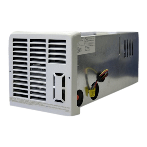
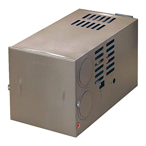
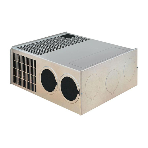
9. Secure furnace to the floorusing the two holes provided in the frontarea ofthe
furnace cabinet. (See Figure 3 or 4.)
CONNECTING GAS SUPPLY
Connect the gas fitting (3/8" NPT to 3/8" Flare) to the furnace at the manifold
provided on the right side of the furnace (Figure 3 or 4). It will be necessary to
hold the flare fitting on the furnace manifold when connecting or loosening gas
line.
NOTE: Be sure all male joints have been treated with a sealing compound
resistant to the action of liquefied petroleum (LP) gas.
NOTE: The appliance must be disconnected from the gas supply piping system
during anypressure testing ofthatsystem attestpressure in excess of 1/2 PSIG.
The appliance must be isolated from the gas supply piping during any pressure
testing of the gas supply piping system at test pressure equal to, or less than 1/2
PSIG.
In order to maintain a check on gas supply pressure to the furnace, Suburban
advises the installer to provide a 1/8" NPT plug tap for test gauge connection
immediately upstream of the gas supply connection to the furnace.
After the furnace has been connected to the gas supply, all joints must be
checked for leaks.
WARNING! Never check for leaks with an open flame. Turn on the gas and
apply soapy water to all joints to see if bubbles are formed.
CONNECTING ELECTRICAL SUPPLY
CAUTION! This furnace is designed for negative ground 12 volt DC system
only. Do not attempt to alter the furnace for a positive ground system or
connectthe furnace directlyto 115volts AC.Damage to furnacecomponent
parts will occur.
Be sure all wiring to the furnace is of heavy enough gauge to keep the voltage
drop through it to a minimum and to provide enough powerfor start-up surge. No.
12 gauge wire is recommended.
If any of the original wire that is supplied with the appliance must be replace, it
must be replaced with Type 105°C or its equivalent.
Connect the power supply to the red and yellow wires in the right side of the
furnace. The wires are color coded, red for positive (+) and yellow for negative (-).
This polarity must be observed so the furnace motor will run with the proper
direction of rotation to insure correct air delivery. (See wiring diagram.)
If the furnace power supply is to be from a convertor, we recommend that the
convertor system used to power the furnace be wired in parallel with the battery.
This will serve two purposes:
1. Provide a constant voltage supply to the furnace.
2. Filter any A.C. spikes or volt surges.
NOTE: Furnace Models NT-12S, NT-16S and NT-20S are equipped with an
electric ignitor device that has an energy consumption of .1 amp at 12 volts DC.
CONNECTING DUCTS TO FURNACE
The following duct requirements must be followed in order to assure proper
operation of the furnace.
A. Maintain a minimum of 25 square inches unrestricted duct area throughout
entire duct system including through register. (Minimum 2 ducts 4" diameter.)
NOTE: Ducts terminating in a dead air space (like holding tank compartments or
cargo areas (Toy Boxes) with no means for return air recirculation should not be
counted in the required ductarea. Also, ducts 2" in diameterorsmaller should not
be counted in the required duct area.
B. Make the duct connections at the furnace cabinet tight. Loose connections will
resultin overheatingofthefurnacecomponentpartsandareductionin theheated
air flow through the duct system.
C. Avoid making sharp turns in the duct system. Sharp turns will increase the
static pressure in the plenum area and could cause the furnace to cycle.
D. Avoid making a lot of turns in the duct system. The straighter the duct system
the better the performance of the furnace.
E. Maintain a minimum of 1" clearance where ducts pass through any combustible
construction; such as, coach cabinetry. (See Figure 4A). NOTE: UL listed duct
materials can be 0" clearance.
F. Do not install air boosters in the duct system. Such devices will cause the
furnace to cycle on limit and to have erratic sail switch operation.
NOTE: After installation ofthe furnace and ductsystem is completed, adjustments
must be made to obtain a temperature rise within the range specified on the
Rating Plate.
The efficiency rating of the furnace is a product thermal efficiency rating
determined under continuous operating conditions independent of any installed
system. CONNECTING THERMOSTAT
Locate the room thermostatapproximately 4 1/2 feet above the flooron an inside
bulkhead where it is not affected by heat from any source except room air.
Connectthermostatwires tothebluewires leavingpowersupplyplug on rightside
offurnace.(Seewiringdiagram.)Ifyourfurnace isequippedwith a thermostatthat
has an adjustable anticipator, the anticipator should be set at .7 amps. If you
desire longer heating cycles, adjust the anticipator to a higher setting. Ifyou desire
shorterheating cycles,adjust the anticipator to a lower setting.Adjustments to the
anticipator setting should be made in .5 amp increments.
INSTALLING VENT
The vent outlet must be installed so it is in the same atmospheric pressure zone
as the combustion air intake.The exhaustand intake tubes must beinstalled from
the outside, pass through the RV skin and slide onto the furnace exhaust and
intake.
WARNING! Donotalterthe ventassemblysupplied with this furnace.Any
modifications willresult in improper installation which could cause unsafe
furnace operation.
CAUTION!Combustion air must not be drawn from the living area.Allair for
combustion must be drawn from the outsideatmosphere.Allexhaustgases
must be vented to the outside atmosphere -never inside the RV. Therefore,
it is essential to insure that the vent cap and tube assemblies are properly
installed.
Suburban recommends all vents be installed using the rain shield supplied.
(See Figure 7)
1. Apply caulking to RV skin behind ventcap as shown in Figure 7. Apply caulking
generously around perimeter of vent cap and across center as shown.
2. Insert intake tube through RV skin and slide it onto the furnace intake (See
Figure 1.) Minimum tube overlap of 1/2" is required.
3. Insert vent cap exhaust tube through RV skin and slide it onto the furnace
exhaust (See Figure 1.) Minimum tube overlap of 1 1/4" is required.
4. Attach vent cap assemblyto outer skin of RV with the six (6) screws provided.
Do not install vent assembly upside down. The words "Suburban" and "Dayton,
Tenn." must be right side up.
PREVENTIVE MAINTENANCE
WARNING! If the user of this appliance fails to maintain it in the condition
in which it was shipped from the factory or if the appliance is not used
solely for its intended purpose or if appliance is not maintained in
accordance with the instructions in this manual, then the risk of a fire
and/or the production of carbon monoxide exists which can cause
personal injury, property damage or loss of life.
CAUTION: Label all wires before disconnecting for servicing. Proper polarity
must be observed so the furnace motor will run with the proper direction of
rotation to insure correct air delivery (See Wiring Diagram.)
CAUTION: Label all wires prior to disconnection when servicing controls.
Wiring errors can cause improper and dangerous furnace operation.
Always verify proper operation of furnace after servicing.
Your furnace should be inspected by a qualified service agency yearly before
turning the furnace on.Particular attention should be given to the following items.
1. Inspect furnace installation and vent termination to be sure furnace is properly
secured in place (See Installation Instructions), that vent terminates to the
atmosphere, and that vent tubesoverlap properly. (See Installing Vent Assembly.)
2. Inspect chamber and venting to assure that these components are physically
sound, without holes or excessive corrosion and that the installation and/or
reinstallationisinaccordancewith Suburban’s InstallationInstructions.(Reference
installation manual supplied with furnace.)
WARNING! It is imperative that the products of combustion be properly
vented to atmosphere and that all combustion air supplied to burner be
drawn from outside atmosphere.
3. Check the base on which furnace is mounted. Be sure it is physically sound,
void of any sagging, deterioration, etc.
4. Inspectfurnace,the venting,ducting and the gas piping to furnace for obvious
signs of deterioration. Correct any defects at once.
5. Inspect combustion chamber for restrictions in exhaust or intake. It is
imperative that the flow of intake combustion air and the flow of exhaust gases
being expelled to the outside atmosphere not be obstructed. Any soot or loose
debris should be blown out using compressed air. (See Figure 10.)
6. Inspect all gaskets. If any gaskets show signs of leakage of deterioration,
replace them. Safe operation of the furnace depends on all gaskets being tight.
7. Inspect return air inlet openings to the furnace. Remove any restrictions to
assure adequate air flow.
You, as the owner/user, should inspect the furnace monthly during the
heating season for presence of soot on vent. Operating the furnace under this
condition could lead to serious property damage, personal injury or loss of life. If
soot is observed on the vent, immediately shut furnace down and contact a
qualified service agency.
Listed below are several safety related items that you should follow during the
heating season to assure continued safe operation of the furnace.
1. Inspectfurnace venting.Venting mustbe free ofobstructions,void ofsootand
properly terminated to the atmosphere. (See Installing Vent Assembly.)
WARNING! Do not install screens over the vent for any reason. Screens
will become restricted and cause unsafe furnace operation. Accessories
are being marketed for RV products which we do not recommend. For
your safety, only factory authorized parts are to be used on your furnace.
2. Periodically inspect the vent for obstructions or presence of soot. Soot is
formed whenever combustion is incomplete. This is your visual warning that the
furnace is operating in an unsafe manner. If soot is present, immediately shut
furnace down and contact your dealer or a qualified service person.
