manuals.online logo
Brands
  1. Home
  2. •
  3. Brands
  4. •
  5. Suburban
  6. •
  7. Furnace
  8. •
  9. Suburban NT-24SP User manual

Suburban NT-24SP User manual

SUBURBAN MANUFACTURINGCOMPANY
PostOfficeBox
399
Dayton, Tennessee
37321
DY
NATRAIL
INSTALLATION INSTRUCTIONS
FOR MODELS
CER~FIEO
NT-24SP NT-30SP NT-34SP
Thedesignofthefurnace hasbeencertifiedforinstallationinrecreationalvehicles only. Inorderforthefurnacetooperateinconformity
with generally accepted safety regulations, the installation instructions must be followed. Failure
to
comply with the installation
instructions will voidthewarranty onthe furnace andany responsibility onthe part of Suburban Manufacturing Company.
Thefurnace wasinspected before
it
leftthe factory. If anyparts arefoundtobedamged, donotinstallthefurnace. Immediately contact
thetransportation company andfile a claim.
WARNING! Improper installation, adjustment, alteration, service or maintenance can
cause property damage, personal injury or loss of life. Refer to the installation
instructions andlor owners manual providedwith this appliance. Installationand service
must be performed by a qualified installer, service agency or the gas supplier.
INSTALLATION INSTRUCTIONS
I
manual. InCanada,the furnace must be installed in accordancewith.
WARNING!
of
this
appliancemust
be
made
in
accordance
with
thewritten instructions provided inthis manual. Noagent, representative
or employee of Suburban or other person has the authority to change,
modify or waive any provision of the instructions contained in this
CAUTION: Ifpossible, do not install the furnace to where the vent can be
Standard
z240
-
coveredor obstructed when any door onthe trailer isopened. Ifthis is not
2.
Standard
z240.6.2-M86
-
ElectricalRequirements
for
possible, then the travel of the door must be restricted inorder toprovide RecreationalVehicles
a
6w
clearance
between
the
furnace
vent
and
any
door
whenever
3. StandardCANICSA 2240.4.2-M86
-
InstallationRequirementsfor Propane
the door is open. NOTE: The exhaust temperature of this furnace could Appliances and Equipment in RecreationalVehicles.
discolor orwarp some materials. You shouldverify that the material used
4.
CAN/CGA
installation
'Odes.
onthecoachdoor, panel, or cover will notdiscolor orwarp fromtheexhaust
5.
applicable local
'Odes
and
regulations.
3. Furnace must be
electrically
grounded in accordancewith the latest ed~tion
of the National
Electrical
Code ANSIINFPA No 70
Th~sunit is equlpped with an electric ignitor device that has an energy
consumptionof .lamp @12 volts D C.
temperature whenever any door, panel, or cover isinthe open position. Return Air
CAUTION: Dueto the differences invinyl siding, this appliance should not There are three methodsdescribed below for installing the furnace. Regardless
beinstalled onvinylsiding without first consultingwiththemanufacturer of of the methodyou choose, we require that a permanentopening be provided in
the siding or cutting the siding away from the area around the appliance theinterlorcabinetryof the coachdirectlyinfront ofthefurnace.Theopening must
vent. allowfor free, unobstructedremovalof the furnace.This openingmaybeusedas
CAUTION: In any installation in which the vent of this appliance can be
coveredduetothe constructionofthe RVorsome special feature ofthe RV
such as slide out, pop-up, etc. always insurethatthe appliance cannot be
operated by setting the thermostat to the positive "OFF" position and
shutting off all electrical and gas supply to the appliance. Never operate
furnace with vent covered.
a meansof providing circulating returnair to the furnace.other openings may be
usedas well. The minimum returnair to the furnace must total 55 square inches
free area It is important that adequate return air be providedto assure normal
heatingandoperationofthefurnace. Failureto providetheminimumreturnairwill
cause erraticfurnace cycling.
A. INSTALLATION DIRECTLY AGAINST OUTERSKIN OF COACH
NOTE:These furnaces must be installed and ventedas described inthis manual (See Figure 1)
so that the negative pressurecreated by the air circulating (return air) fan cannot
affect the combustion air intake or ventina of any other a~~liance.Itis imoerative
I
wall
thickness
for
this
type
instal'ati0n
is
3".
1
that the productsofcombustion be prdpezyveniedto theatmosphere and that all the furnace near lengthwise
center
of
the
Do
not
install
the
combustionair supplied to burner be drawn from the outside atmosphere. (See
furance
with
the
vent
facing
toward
the
end
of
the coach,
'InstallingVent Assembly'.) 2. Choose a location for installation out of the way of wires, pipes, etc. which
IMPORTANT: If this furnace is to be connected to a common duct system also
might
interfere
with
the
installation,
Adhere
to ,he
clearances
from
,he
sewing a cooling unit, a manual or automatic damper is required to prevent any
cabinet
tocombustible construction
as
listed
in Table
cold conditioned air from circulating back into the furnace. Cold air passing over
thefurnacecombustionchamberduringtheoperationofthecooling result NOTE:Side and top clearances maybe
0"
for through the wall installations upto
in the formation of condensation inside the furnace combustion chamber This
a
maximum wall
thickness
Of
3".
(See Figure
condensation may promote corrosion and premature failure of the combustion
chamber.
NOTE: These furnaces shall be installed so the electrical components are
protectedfrom water.
These furnaces are design certified for PropaneILP gas only. Do not attempt to
convert to natural gas.
Gas supply pressure for purposes of input adjustment.
Minimum
-
11" W.C.' Maximum
-
13W.C.'
(W.C.'
-
Water Column)
3.
When an appliance isinstalleddirectly oncarpeting,tileor othercombustible
material,other than wood flooring, the appliance shall be installed on a metal or
wood panel extending the full width and depth of the appliance. If preferred,the
carpeting,tileor combustiblematerials,other than wood maybecut away the full
length and depth of the appliance plus the appliance minimum clearances to
combustibles.(See Table 1
.)
4.
Cut an openingthrough the inner wall 12 7/16 x 13".Thiswill allowthe rear of
the furnaceto be installed against the outer skin of the coach.(See Figure 1
.)
5.
Cut two 2 114" diameter holes through the outer skin of coach as shown in
Figure 1
In the U.S.A., the
installation
of the furnace must be in accordance wlth local 6. put furnace in place, making sure that rear of furnace cabinet IS as close to
codes and regulations. Inthe absence of localcodesand regulations,referto the outer skin of coach as possible and still assure proper vent tube overlap. (See
latest ed~tionof: InstallingVent Assembly).
1. Standard for Recreat~onalVehicles ANSl A-119.2lNFPA 501C.
2. National Fuel Gas Code ANSl 2223.1. 7. Fasten furnace to floor of coach using the two (2) holes provldedin the front
plenumarea of furnacecabinet. (See Figure 1.)
8.
Installvent assembly. (See instructions for installing vent.)
Form No. 2469-C
B.
INSTALLATION DIRECTLYAGAINST INNERWALL OFCOACH
(See Figure2)
I
Maximumwall thlckness for thls
type
InstallationIs2 114.
1
1. Locatethe furnace near lengthwisecenterof the coach. Do not installthe
furnace with the vent facing towardthe forward end of the coach.
2. Choose a location for installation out of the way of wires, pipes, etc. which
might interferewith the installation.Adhere to the mihimum clearancesfrom the
cabinet to combustible constructionas listed in Table 1. Refer to Figure3 for
illustrationof furnace clearances.
3.
When an wpliance is installedJirectly on carpeting,tileor othercombustible
material,other than wood flooring,the appliance shall be installedon a metalor
wood panel extendingthe full width and depth of the appliance.
If
preferred, the
carpeting, tile or combustiblematerials,otherthanwood maybecut away the full
length and depth of the appliance plus the appliance minimum clearances to
combustibles. (See Table 1
.)
4.
Locatecenterlinesforexhaust and intaketubesas shownin Figure 1.Cut two
2
314 diameter holes throughcoach wall for exhaust and intake. (See Figure
2.)
5.
Put furnace in place, making sure that rearof furnace cabinet is as close to
inner wall of coach as possibleand still assure propervent tube overlap. (See
InstallingVent Assembly).
6.
Fastenfurnace to floor of coach usingthe two holesprovidedin front plenum
areaof furnace cabinet. (See Figure 1
.)
7.
Installvent assembly. (See instructionsfor ~nstallingvent.)
C. INSTALLATION USINGVENT EXTENSIONTUBES
When it is not possible to installthe furnace as describedin installationsA or 0.
extensiontubes mustbe usedto connectthe exhaust and intaketube to the vent
assembly on the outsideof the coach.
Avoid the useof extension tubes whenever possible.
If
they must be used, it is
importantthat the correct length tubes are used.
Inorder to determinethe correctextensiontube kit,you mustdetermine the range
in which the extension falls. To do this, position the furnace in its permanent
locationand measurethe distance from the end of the exhaust and intaketube
lothe outeredgeof the coachskin.Thisdeterminesthe extension tube rangeyou
need. Figure4 lists by kit number the vent extension rangeup to
9".
Example: If thedistanceyou measuredis2
7/8",
usingFigure4as your guide,you
will order Kit #520498,which accommodatesa range from 2 114" to 3 118". The
extensiontube kit comes with complete installationinstructions.
TABLE
1
INSTALLING VENT ASSEMBLY
The vent outlet must be installedso it is in the same atrnospllericpressurezone
as the combustion air intake. The exhaust and intake tubes must be installed
from the outside, pass through the RV skin and slide onto the furnace exhaust
and intake.
I
WARNING!Donotalter the ventassembly suppliedwith this furnace. Any
modifications will result in improper installation which could cause
I
(unsafefurnace operation.
I
CAUTION!Combustion air mustnot
be
drawnfromthe livingarea. Allalr for
combustion rnust
be
drawnfromtheoutsideatmosphere.Allexhaust gases
mustbeventedtotheoutsideatmosphere
-
never insidethe
RV.
Therefore,
itisessential to insurethat the vent cap and tube assemblies are properly
installed.
1.Apply caulkingto RVskin behindvent capasshowninFigure2.Applycaulking
generously aroundperimeterof vent cap and acrosscenter as shown.
2. lnsert intake tube through RV skin and slide it onto the furnace intake (See
Figure 2.) Minimumtube overlapof 112" is required.
3.
lnsert vent cap exhaust tube through RV skin and slide it onto the furnace
exhaust (See Figure 2.) Minimumtube overlapof 1 114" is required.
4.
Attach vent capassemblyto outerskin of RVwith the six (6)screwsprovided.
Donot installvent assembly upside down. The words "Suburban" and "Dayton.
Tenn." must be right side up.
5.
Attach the vent assembly to the furnace using the special 3 112" screw
provided.Insertscrewthroughholeprovidedinexhaustopeningof vent assembly
andsecure to bracketinexhaust tube of fumace. This anchorsthe fumace to the
vent assembly and the outer skin of the RV (See Figure2.)
CONNECTINGGAS SUPPLY
Connect the gassupplyto the fumace
at
the manifold,following the suggestions
outlinedbelow:
NOTE: The compound usea on threadedjoints must be resistant to liquefied
petroleum(LP) gas.
NOTE:The appli&,~cemust be dis~&~inectedfrom the gas supply piping system
duringanyaressure testing ofthat systemat test pressure in accessof 112 PSIG.
The appl~ancemust be ~solatedfrom the gas supply plplng dur~ngany pressure
testingof the gassupplypiplngsystemat test pressureequal to, or lessthan. 112
PSIG
1. Be sure that the gas fitting is outside of the furnace jacket and easily
accessible.(SeeFigure1
.)
The fittingmay be connecteddirectlyto the 90" elbow
at the gas inlet to the furnace. To assure an airtight seal, be sure the gasket
providedwith the furnaceis installedbetweenthe fittingand the furnace cabinet,
as illustratedin Figure 1.
If
this gasket isomitted, it could resultinoverheatingof
component partswithin the furnace.
2. In order to maintaina check on gas supplied pressure to the fumace, a 118"
NPT plug tap must
be
installed and accessible for test gauge connection
immediatelyupstream of the gas supply connectionto the fumace.
3.
After the furnace has been connected to the gas supply, all joints must
be
checkedfor leaks.
WARNING! Nevercheckfor leakswithanopenflame. Turnonthe gasand
apply soapywater to alljoints to
see
if bubblesare formed.
CONNECTING ELECTRICAL SUPPLY
CAUTION:Thisfurnace isdesignedfor negative ground12voltD.C. system
only. Do not attempt to alter the furnace for a positive groundsystem or
connect the furnace directly to 115 volts A.C. Damage to furnace
component parts will occur.
Be sure all wiring to the fumace is of heavyenough gauge to keep the voltage
drop through it to a minimum.No. 12gauge wire is recommended.
If
any of the
original wire that is supplied with the appliance must be replaced, it must
be
replacedwith Type 105°Cor its equivalent.
Connect the power supply to the quick connect pigtail on the right side of the
fumace.The wiresare color coded, redfor positive
(+)
andyellow for negative
(-).
This polarily must be observed so the furnace motor will run with the proper
directionof rotationto insurecorrect air delivery. (See wiring diagram.)
If the furnace power supply is to
be
from a convertor, we recommend that the
convertorsystem usedto power the fumace be wired inparallel withthe battery.
Thiswill servicetwo purposes.
1. Providea constant voltage supply to the furnace.
2. Filterany A.C. spikes or volt surges.
CONNECTINGDUCTSTO FURNACE
The following duct requirements must be followed in order to assure proper
operationof the furnace.
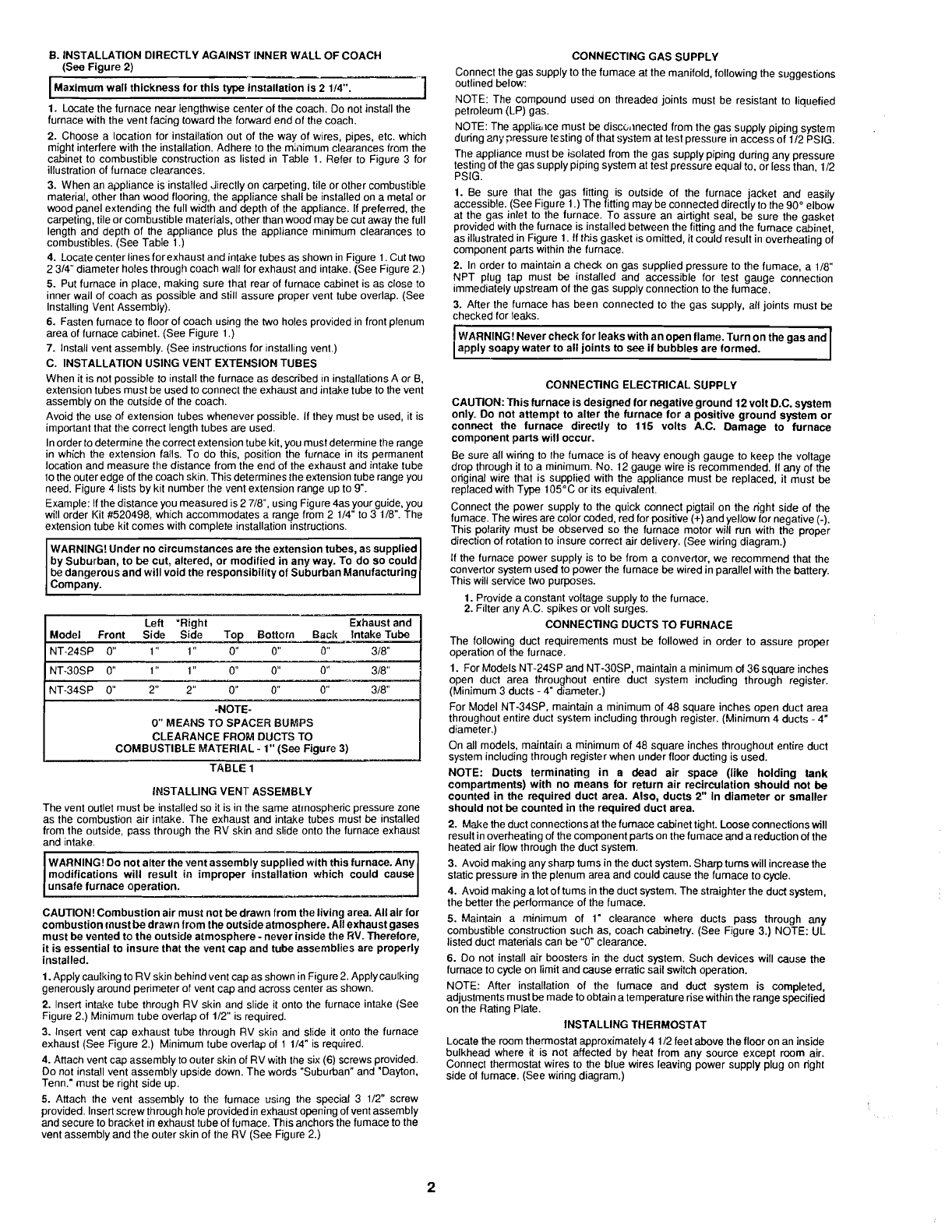
1. ForModelsNT-24SPand NT-30SP,maintaina minimumof 36squareinches
open duct area throughout entire duct system including through register.
(Minimum3 ducts
-
4" diameter.)
For Model NT-34SP, maintain a minimum of
48
square inches open duct area
throughout entire duct system includingthrough register.(Minimum4 ducts
-
4"
diameter.)
On all models, maintair~a minimumof 48 square inches throughout entire duct
system includingthrough registerwhen under flwrductingis used.
NOTE: Ducts terminating in a dead air space (like holding tank
compartments) with no means for returnair recirculation should not
be
counted inthe required duct area. Also, ducts
2"
Indiameter or smaller
shouldnot
be
counted inthe requiredduct area.
2. Makethe duct connectionsat the furnace cabinettight. Looseconnectionswill
resultinoverheatingof the component partson thefumaceanda reductionof the
heatedair flow through the duct system.
3.
Avoidmakingany sharptums intheduct system. Sharpturnswill increasethe
staticpressureinthe plenum area and could causethe fumace to cycle.
4.
Avoidmakingalotof tums intheduct system. The straighterthe duct system,
the betterthe performanceof the fumace.
5.
Maintain a minimum of 1" clearance where ducts pass through any
combustibleconstructionsuch as, coach cabinetry. (See Figure
3.)
NOTE: UL
listedduct materialscan
be
"0" clearance.
6.
Do not install air boosters in the duct system. Such devices will cause the
furnace to cycleon limit and cause erraticsail switchoperation.
NOTE: After installation of the furnace and duct system is completed.
adjustmentsmust
be
madeto obtaina temperaturerisewithinthe rangespecified
onthe RatingPlate. INSTALLINGTHERMOSTAT
Locatethe rwmthermostatapproximately4 112 feet above the flooron an inside
bulkhead where it is not affected by heat from any source except rwm air.
Connect thermostat wires to the blue wires leaving power supply plug on right
side of fumace. (Seewiring diagram.)

Other manuals for NT-24SP

1

This manual suits for next models

2

Other Suburban Furnace manuals

Suburban SH-35 User manual

Suburban

Suburban SH-35 User manual

Suburban SF-42F User manual

Suburban

Suburban SF-42F User manual

Suburban SF-20 User manual

Suburban

Suburban SF-20 User manual

Suburban SF-20FQ User manual

Suburban

Suburban SF-20FQ User manual

Suburban DD-17DSI User manual

Suburban

Suburban DD-17DSI User manual

Suburban SF-20 User manual

Suburban

Suburban SF-20 User manual

Suburban NT-12S User manual

Suburban

Suburban NT-12S User manual

Suburban SH-35F User manual

Suburban

Suburban SH-35F User manual

Suburban SA25N Quick start guide

Suburban

Suburban SA25N Quick start guide

Suburban NT-12S User manual

Suburban

Suburban NT-12S User manual

Suburban DYNATRAIL NT-40 Guide

Suburban

Suburban DYNATRAIL NT-40 Guide

Suburban SH-42 Guide

Suburban

Suburban SH-42 Guide

Suburban NT-16SEQ Guide

Suburban

Suburban NT-16SEQ Guide

Suburban NT.12SE Guide

Suburban

Suburban NT.12SE Guide

Suburban NT-12S User manual

Suburban

Suburban NT-12S User manual

Suburban NT.12SE Guide

Suburban

Suburban NT.12SE Guide

Suburban NT-24SP Guide

Suburban

Suburban NT-24SP Guide

Suburban NT-16SEQ User manual

Suburban

Suburban NT-16SEQ User manual

Suburban NT-16SQ Guide

Suburban

Suburban NT-16SQ Guide

Suburban NT.16SE Guide

Suburban

Suburban NT.16SE Guide

Suburban SF-42 User manual

Suburban

Suburban SF-42 User manual

Suburban SF-42F User manual

Suburban

Suburban SF-42F User manual

Suburban DYNATRAIL NT-40 User manual

Suburban

Suburban DYNATRAIL NT-40 User manual

Suburban SFV-30 Installation guide

Suburban

Suburban SFV-30 Installation guide

Popular Furnace manuals by other brands

Goodman GCVM970803BN User's information manual

Goodman

Goodman GCVM970803BN User's information manual

Barnstead International 1260 Series Operation manual and parts list

Barnstead International

Barnstead International 1260 Series Operation manual and parts list

York TL8E installation manual

York

York TL8E installation manual

Rinnai ENERGYSAVER EX08C Conversion manual

Rinnai

Rinnai ENERGYSAVER EX08C Conversion manual

United States Stove HOTBLAST 1500 Owner’s Instruction and Operation Manual

United States Stove

United States Stove HOTBLAST 1500 Owner’s Instruction and Operation Manual

Daikin 90 Plus AFUE Installation & commissioning

Daikin

Daikin 90 Plus AFUE Installation & commissioning

Bryant 333B-AV-036060-AA-JA troubleshooting guide

Bryant

Bryant 333B-AV-036060-AA-JA troubleshooting guide

Lennox G71MPP installation instructions

Lennox

Lennox G71MPP installation instructions

Carrier Deluxe 58DLA installation manual

Carrier

Carrier Deluxe 58DLA installation manual

Carrier 58EFB Installation, start-up, and operating instructions

Carrier

Carrier 58EFB Installation, start-up, and operating instructions

Lennox G40DF?24A?045 Unit information

Lennox

Lennox G40DF?24A?045 Unit information

Timberwolf TF100 Installation and operating instructions

Timberwolf

Timberwolf TF100 Installation and operating instructions

Bryant GAS-FIRED INDUCED-COMBUSTION FURNACES 383KAV Installation, start-up, and operating instructions

Bryant

Bryant GAS-FIRED INDUCED-COMBUSTION FURNACES 383KAV Installation, start-up, and operating instructions

Lennox ML180UH SERIES installation instructions

Lennox

Lennox ML180UH SERIES installation instructions

Amana ACSS920402BN Technical manual

Amana

Amana ACSS920402BN Technical manual

Lennox G24M2-45 installation instructions

Lennox

Lennox G24M2-45 installation instructions

Trane S8B1D120M5PSBA Installer's guide

Trane

Trane S8B1D120M5PSBA Installer's guide

York TM8T Technical guide

York

York TM8T Technical guide

manuals.online logo
manuals.online logoBrands
  • About & Mission
  • Contact us
  • Privacy Policy
  • Terms and Conditions

Copyright 2025 Manuals.Online. All Rights Reserved.