manuals.online logo
Brands
  1. Home
  2. •
  3. Brands
  4. •
  5. Suburban
  6. •
  7. Furnace
  8. •
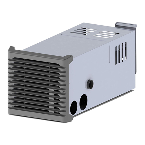
  9. Suburban SH-35F User manual

Suburban SH-35F User manual

SUBURBANMANUFACTURINGCOMPANY
676
BroadwayStreet
Dayton, Tennessee
37321
a
subsidiary
of
AIRXCEL,'~~~.
SUBURBAN GAS FURNACES
CER~FIU
INSTALLATION INS'TRUCTIONS
FOR MODELSSH-35F SH-42F
The design ofthefurnacehasbeenlistedfor installation inrecreationalvehicles only. Inorderforthefurnace tooperateinconformity
with generally accepted safety regulations, the installation instructions must be followed. Failure to comply with the installation
instructionswill void the warranty onthe furnace andany responsibilityonthe partofSuburban ManufacturingCompany.
Thefurnacewasinspectedbefore
it
leftthefactory. Ifanypartsarefoundtobedamaged, donotinstallthefurnace. Immediatelycontact
the transportation company andfile a claim.
FOR YOUR SAFETY
WHAT TO DO IFYOU SMELL GAS:
Extinguishany openflame.
Evacuate all personsfromthe vehicle.
Shut off the gas supply at the gas
container orsource.
Do not touch anv electrical switch. or
use any phoneor radiointhe vehicle.'
Do not start the vehicle's engine or
electric generator.
Contact the nearest gas supplier or
qualified servicetechnician for repairs.
If you cannot reach a gas supplier or
qualified service technician, contact the
nearestfire department.
Do not turn onthe gas supply until the
gas leak(s)has been repaired.
FOR YOUR SAFETY
DO NOT STORE OR USE GASOLINE OR
OTHER FLAMMABLE VAPORS AND
LIQUIDS IN THE VICINITY OF THIS OR
ANY
OTHER APPLIANCE.
WARNING! Improper installation,
adjustment, alteration, service or
maintenancecancausepropertydamage,
personalinjuryorloss oflife. Refer tothe
installation instructions and/or owners
manual provided with this appliance.
Installation and service must be
performedbya qualified installer, service
agency orthe gas supplier.
I
1
This book contains instructions covering the operation and
maintenance ofyour furnace. Keepwith
unit
at alltimes.
IWARNING!
Be sure the furnace and all!
Should you require further information, contact your dealer or
nearest Suburban ServiceCenter.
ignition systems are "OFF" during any
type of refueling and while vehicle is in
1
motionor beingiowed.
INSTALLATION INSTRUCTIONS
WARNING! Installationofthisappliancemustbemadeinaccordancewith
thewritten instructionsprovidedinthismanual.Noagent. representative
or employee of Suburban or other person has the authority to change,
modify or waive any provision of the instructions contained in this
manual.
These furnaces are designedand installedinsuch a manneras to be removable
only from within living area of the recreationalvehicle.
CAUTION: Ifpossible, do not install the furnace to where the vent can be
coveredor obstructedwhen any door onthe trailer is opened.lf this isnot
possible, thenthe travel of the door mustberestricted inorder to provide
a
6"
minimumclearance between the furnace vent andany door whenever
the door isopened.
NOTE: The exhaust temperature of this furnace could discolor or warp some
CAUTION: Dueto the differences invinyl siding, this appliance should not
beinstalledonvinylsidingwithoutfirstconsultingwiththe manufacturer of
the siding or cutting the siding away from the area around the appliance
vent
CAUTION: In any installation inwhich the vent of this appliance can be
coveredduetothe construction ofthe RV or somespecialfeature ofthe RV
such as slide out, pop-up etc. always insurethat the appliance cannot be
operated by setting the thermostat to the positive "OFF" position and
shutting off all electrical and gas supply to the appliance. Never operate
furnace withvent covered.
NOTE: These furnaces must be installedand vented as describedinthis manual
so that the negativepressurecreatedbythe air circulating(returnair) fan cannot
affectthe combustionairintakeorventing of any other appliance. Itisimperative
thatthe productsof combustionbe properlyventedto the atmosphereand that all
combustionair suoolied to burnerbe drawn from the outside atmosohere. (See
materials.You should verrfy that the materialused onthe coachdoor, panel, or InstallingVent ~~iembl~.)
cover will notdiscoloror warp from the exhaust temperaturewheneverany door.
panel, or cover is inthe open pos~t~on. NOTE: Do not install the furnacewith the vent facingtowardthe forward end of
the coach.
FormNo.
2532-C
IMPORTANT:If this fumace is to be connected to a common duct system also
servinga cooling unit, a manual or automatic damper is required to preventany
cold conditionedair from circulating back into the furnace. Coldair passing over
the fumacecombustionchamberduringtheoperationofthecooling unitcanresult
in the formation of condensation inside the furnace combustion chamber. This
condensation may promote corrosion and premature failure of the combustion
chamber.
NOTE: These fumaces shall be installed so the electrical components are
protectedfrom water.
Thesefumaces are design certified for propanelLP gas only. Do not attemptto
convertto naturalgas.
Gassupply pressurefor purposes of input adjustment:
Minimum
-
11" W.C.' Maximum
-
13" W.C.
"
(W.C.'
-
Water Column).
In the U.S.A.. the installationof the fumace must be in accordance with local
codesand regulations. Inthe absenceof local codes and regulations,refer to the
latestedition of:
I.
Standardfor RecreationalVehicles ANSl A-I19.2lNFPA 501'2.
2.
NationalFuel Gas Code ANSl 2223.1.
3.
Furnacemust beelectricallygrounded inaccordancewith the latesteditionof
the NationalElectricalCodeANSllNFPA No. 70.
In Canada,the fumace must be installed inaccordancewith:
I.
StandardCANICSA-Z240RecreationalVehicles.
2. CSA Standard CANICSA-Z240.6.2-M86 Electrical Requirements for
RecreationalVehicles.
3.
Standard CANICSA-Z240.4.2-M86 Installation Requirements for Propane
Appliancesand Equipmentin RecreationalVehicles.
4. CANICGA-6149 InstallationCodes.
5.
Any applicablelocal codes and regulations.
This unit is equipped with an electric igniter device that has an energy
consumptionof
.l
amp
@
12 volts D.C.
RETURN AIR
Therearetwo (2)methodsdescribed belowfor installingthe furnace. Regardless
of the methodyou choose, we require that a permanentopening be providedin
theinteriorcabinetfyofthe coachdirectlyinfrontofthefumace. Theopening must
allowforfree, unobstructedremoval of thefumace.Thisopening maybe usedas
a meansof providingcirculatingretumair to the fumace. Otheropenings maybe
usedaswell. Itisimportantthatadequate returnair be providedto assurenormal
heatingand operationof thefumace. Failureto providethe minimum
retumairwill
causeerraticfurnacecycling. Referto the chart shown belowfor minimumreturn
air requirements.
NOTE: Returnair must be from within the living area of the coach.
ReturnAir Requirements
Model MinimumFree(unobstructed) Area
INSTALLINGTHE FURNACE
NOTE: Beforeinstallingthe fumace
'X"
dimensionasillustratedin Figure2 must
be determined.
SH-35F
SH-42F
I.
Locatethe furnace near lengthwise center of thecoach
55 Sq. In.
142Sq. In.'
'may be reduced to
88
sq.
in.
min.
if
5
ducts
are
used.
2. Choosea locationfor installation out of the way of wires, pipes, etc.. which
mightinterferewith the installation. Adhere to the minimumclearancesfrom the
cabinet to combustible construction as listed in Table 2. Refer to Figure 3 for
illustrationof furnace clearances.
TABLE
I
NOTE:Sideandtop clearancesmay be"0"for throughthewallinstallationsupto
a maximumof
3"
wall thickness.(See Figure 1
.)
3.
When anapplianceisinstalled directly on carpeting,tile or other combustible
material,otherthan wood flooring, the appliance shall be installedon a metalor
wood panel extendingthe full width and depth of the appliance. If preferred. the
carpeting, tileor combustiblematerials,otherthanwood maybecutaway thefull
length and depth of the appliance plus the appliance minimum clearances to
combustibles.(See Table 2.)
4. Determine'x" dimensionas shown in Figure 2. The tubes supplied with the
fumace will accommodate an installation range for 'x" from 1-112"
-
3".
If "x"
dimension is less than 1-112" or greater than 3", then special vent tubes as
chartedinFigure2 must be ordered.
WARNING! Do not alter, cut or otherwise modify the vent tubes as
supplied by Suburban. Doing so could result in inadequate intake of
combustionair orimproperventing offurnace exhaust
5.
After determining'x" dimension, complete the fumace installationas follows:
A. IFINSTALLEDDIRECTLYAGAINSTOUTER SKlNOR
"X"
DIMENSIONIS
0
-
1-112"
I.
Vent Kit 520597must beordered. Do not cut or alter the vent tubes supplied
with the fumace.
2. Cutan openingthroughtheinnerwall 17-314 x8". Thiswill allowthe rearof the
furnaceto beinstalled againstthe outer skin of the coach. (See Figure 1.)
3.
Cut two 2-114" diameter holes throughthe outer skin of the coach, as shown
inFigure
1.
4. Put fumace inplace, making sure that rearof furnace cabinet is as close to
outer skin of coach as possible and still assure proper vent tube overlap. (See
InstallingVent Assembly.) Secure furnace to cabinet.
5.
Using the two 10 x 314 stainless screws provided, fasten furnace to floor of
coachthrough the two holesprovidedinthe frontplenumareaof fumacecabinet.
(See Figure 1
.)
6.
Installvent assembly. (See instructionsfor installingvent.)
B. IF NOT INSTALLED AGAINST OUTER SKlN AND
"Xu
DIMENSION
GREATER THAN 1-112"
I.
Determine "x" dimension as illustrated in Figure 2. Tube length for 'x"
dimensionare charted. Special tubes, if needed, must be ordered.
2.
Locate center lines for exhaust and intake tubes as shown Figure 1. Cut two
2-314" diameterholesthroughcoachwallfor exhaust and intake. (See Figure2.)
3.
Put furnacein place and securefumace to cabinet. (See Figure 1
.)
4.
Using the two 10 x 314 stainless screws provided, fasten to floor of coach
through two holesprovided in front plenum area of furnace cabinet.
5.
Installvent assembly.(See instructionsfor InstallingVent.)
6.
Reinstallcabinet front.
Left Right Exhaustand
Model Front Side Side Top Bottom Back IntakeTube
SH-35F 1" 1"
1"
1"
0"
0"
318
SH-42F
1"
2" 2" 1" 0" 0" 318"
-NOTE-
0"
MEANSTO SPACER.BUMPS
CLEARANCE FROM DUCTSTO
COMBUSTIBLE MATERIAL
-
114" (See Figure
3)
TABLE 2
INSTALLINGVENT ASSEMBLY
The vent outlet must be installed so it is inthe same atmosphericpressurezone
asthe combustionairintake.Theexhaust and intaketubes mustbeinstalledfrom
the outside, pass through the RV skin and slide onto the fumace exhaust and
intake.
WARNING! Donotaltertheventassembly
suppliedwith thisfurnace.Any
modificationswillresultinimproperinstallationwhichcouldcauseunsafe
furnace operation.
CAUTION! Combustionair mustnotbedrawnfromthe livingarea. Allairfor
combustionmustbedrawnfromthe outsideatrnosphere.Al1 exhaustgases
mustbevented tothe outsideatmosphere
-
neverinsidethe RV. Therefore,
itisessentialtoinsurethat thevent cap and tube assemblies are properly
installed.
I.
Applycaulkingto RVskin behindventcap asshownin Figure1. Applycaulking
generouslyaround perimeter of vent cap and across centeras shown.
2. Insert intake tube through RV skin and slide it onto the furnace intake (See
Figure2.) Minimum tube overlap of 112" is required.
3.
Insert vent cap exhaust tube through RV skin and slide it onto the furnace
exhaust(See Figure 2.) Minimum tube overlap of 1 114" is required.
4. Attach vent capassemblyto outer skin of RVwith the six (6)screws provided.
Do not installvent assembly upsidedown. The words "Suburban" and "Dayton.
Tenn." mustbe right side up.
CONNECTINGGAS SUPPLY
Connect the gassupplyto thefumace atthe manifold,followingthe suggestions
outlinedbelow. ltwillbenecessaryto holdtheflarefittingon thefumace manifold
when connecting or looseninggas line.
NOTE: The compound used on threaded joints must be resistant to liquefied
petroleum(LP)gas.
NOTE: Theappliance must be disconnectedfrom the gas supply piping system
dunngany pressuretesting of that systemat test pressureinexcessof 112 PSIG.
The
appliance
must be isolatedfrom the gas supply piping doring any pressure
testingof the gas supply piping system at test pressureequalto or less than 112
PSIG.
I.
Connectgas line to the 318" elbow at the front of the fumace. (See Figure 1.)
Some standards may requirethe use of a manual shut off valve in the gas line
externalto the fumace cabinet.
2. Inorderto maintaina check ofgassuppliedpressuretothefumace. Suburban
advisesthe installerto provide the 118" NPT plug tap for test gauge connection
immediatelyupstreamof the gas supplyconnectionto the furnace and that it be
readilyaccesible.
3.
After the fumace has been connected to the gas supply, all joints must be
checkedfor leaks.
WARNING!Nevercheckforleakswithanopenflame.Turnonthegasand
apply soapy water toalljointstosee ifbubblesare formed.
CONNECTING ELECTRICAL SUPPLY
CAUTION: Thisfurnaceisdesignedfornegativeground12voltD.C. system
only. Do notattempt to alter the furnace for a positive ground system or
connectthefurnacedirectly to 115vo1tsA.C. Damagetofurnacecomponent
partswill occur.
Be sure all wiring to the furnace is of heavyenough gauge to keep the voltage
dro~throuahitto a minimumandto orovideenouah Dowerfor start-uo surae. No.
12gaugewire is recommended.lfanyof theorig;ai wire that issuppliedwith the
appliancemustbereplaced,itmustbereplacedwithtype 105"Cor itsequivalent.
Powersupplyconnectionsareto beontherightsideofthefurnace. Thewires are
colorcoded, redfor positive
(+)
and yellow for negative
(-).
This polaritymust be
observed so the furnacemotorwill run the proper directionof rotation to insure
correctair delivery. (Seewiring diagram.)
If the furnace power supply is to be from a converter, we recommend that the
convertersystemusedto power thefurnace be wired inparrallelwiththe battery.
This will servetwo purposes:
I.
Providea constant voltage supplyto thefurnace.
2. Filter anyA.C. spikes or volt surges.
CONNECTING DUCTS TO FURNACE
The following duct requirements must be followed in order to assure proper
operation of the furnace:
A. The minimumopen duct areas listed below must be maintainedthroughout
entireduct system including through register:
SH-42F
1
48 SQ. IN.
I
4
(
4"
1
56 SQ. IN.
I
72SQ. IN.
'SH-42F
Bottom
Duct requires use
of Bottom
Duct Kit,
Part
No.
520864.
NOTE:
Ducts terminating in a dead air space (like holding tank
compartments) with no means for return air recirculation should not be
counted inthe required duct area. Also, ducts 2" indiameter or smaller
shouldnotbecounted inthe required duct area.
B. Maketheductconnectionsatthefurnacecabinet tight. Looseconnectionswill
resultinoverheatingofthecomponentpartson thefurnaceand a reductionofthe
heatedair flow throughthe duct system.
C. Avoid makinganysharp turnsinthe duct system.Sharpturnswillincreasethe
static pressureinthe plenumarea and could cause the furnace to cycle.
D. Avoid makingalot ofturns inthe duct system. Thestraightertheductsystem,
the better the performanceof the furnace.
E. Maintain a minimum of 114" clearance where ducts pass through any
combustible construction,such as coachcabinetry. (See Figure
3.)
NOTE: UL
listedduct materialscan be
0
clearance.
F. Do not install air boosters in the duct system. Such deviceswill cause the
furnace to cycle on limitand to have erratic sail switch operation.
NOTE:Afterinstallationofthefurnaceandductsystemiscompleted,adjustments
must be made to obtain a temperature rise within the range specified on the
Rating Plate. INSTALLINGTHERMOSTAT
Locatethe roomthermostatapproximately
4-112 feetabove theflooronan inside
bulkhead where it is not affected by heat from any source except room air.
Connectthermostatwiring to the bluewireson right side offurnace. (Seewiring
diagram.)
PREVENTIVEMAINTENANCE
MODEL
SH-35F
inwhich
it
was shipped from the factory or ifthe appliance isnotused
solely for its intended purpose or if appliance is not maintained in
accordance with the instructions inthis manual, then the risk of a fire
andlor the production of carbon monoxide exists which can cause
CAUTION:Labelallwires
beforedisconnedingforservicing.
Properpolarity
mustbeobservedso thefurnacemotorwill runwiththeproperdirection of
rotationto insure correctair delivery. (See wiring diagram).
CAUTION: Labelall wires prior todisconnection whenservicing controls.
Wiring errors cancause improper and dangerous furnace operation.
SlDE DUCTS
Always verify proper operationoffurnace after servicing.
TOP DUCT
Min. Open
DuctArea
56 SQ. IN.
Your fumace should be inspectedby a qualifiedservice agency yearly before
turningthe furnace on. Particularattentionshouldbegivento thefollowing items.
BOTTOMDUCT
Min. Open
DuctArea
56 SQ. IN.
Duct
Size
4"
Min. Open
DuctArea
48
SQ. IN.
I.
lnspectfurnace installationandventterminationtobesurefurnace isproperly
secured in place (see Installation Instructions), that vent terminates to the
atmosphere,and thatventtubesoverlapproperly(seeInstallingVentAssembly.)
Min. No.
DuctsUsed
4
2. lnspectchamberand venting to assurethat these components are physically
;
.: sound without holes or excessive corrosion and that the installationandlor re-
:
'
p
~nstallationisinaccordancewith Suburban's installationinstructions.(Reference
';-/
~nstallationmanual suppliedwithfumace.)
WARNING! Itisimperative that the productsofcombustion beproperly
vented to atmosphere and that all combustion air supplied to burner be
drawnfrom outsideatmosphere.
3. Check the base onwhich furnace is mounted.Be sure it isphysicallysound.
void of any sagging, deterioration, etc.
4. lnspect furnace, the venting, ducting and gas piping to furnace for obvious
signs of deterioration. Correctany defects at once.
5. lnspect combustion chamber for restrictions in exhaust or intake. It is
imperativethat the flow of intake combustion air and the flow of exhaust gases
being expelledto the outside atmosphere not be obstructed. Any soot or loose
debris should be blownout usingcompressedair. (See Figure
6.)
6. lnspect all gaskets. If any gaskets show signs of leakage or deterioration.
replacethem. Safe operation of the furnace depends on all gaskets being tight.
7. lnspect return air inlet openings to the furnace. Remove any restrictions to
assureadequateair flow.
You, as the ownerluser, should inspect the furnace monthly during the
heating seasonfor presenceof soot on vent. Operatingthe furnace underthis
conditioncould leadto serious propertydamage, personal injury or lossof life. If
soot is observedon the vent, immediately shut the furnace down and contacta
qualifiedserviceagency.
Listed below are several safety related itemsthat you should follow during the
heatingseasonto assurecontinued safeoperationof the furnace.
1. lnspectfurnace venting.Ventingmust befree of obstructions,vo~dof soot,and
properly terminated to the atmosphere.(See InstallingVent Assembly.)
WARNING! Do notinstall screens over theventfor any reason. Screens
will becomerestrictedandcause unsafefurnaceoperation.Accessories
are being marketed for RV productswhich we do not recommend. For
2. Periodically inspect the vent for obstructionsor presence of soot. Soot is
formed whenever combustionisincomplete.This isyour visual warning that the
furnace is operatingin an unsafe manner. If soot is present, immediatelyshut
fumace down and contact your dealer or a qualifiedservice person.
3. Keepfurnace clean.Morefrequent cleaningmaybe requireddue to excessive
lint from carpeting. bedding material, etc. It is imperative that control
compartments,burnersandcirculatingair passagewaysof theappliance be kept
clean.
4. The motor is permanently lubricatedand requires no oiling.
5. Keepthe furnace area clear of any combustible materials, gasoline or other
flammablevapor and liquids.
6.
Beforeoperatingfurnace, check the locationofthefurnace vent to makesure
itwill not beblockedbytheopeningofanydooronthe trailer. Ifit canbe blocked.
do not operatethe fumacewith the dooropen.
7. Do not restrict the flow of combustion air or the warm air circulation to the
furnace. To do so could cause personalinjuryandlor death.
8.
Never operate the furnace ifyou smellgas. Do not assume that the smell of
gas in your RV is normal. Any time you detect the odor of gas, it is to be
considered life threatening and corrected immediately. Extinguish any open
flamesincludinaciaarettesandevacuateail oersonsfromthevehicle.Shutoffoas
supply at LP gas Gottle. (See safety notice bnfront cover of this manual.)
9.
Immediatelyshut furnace down and call a service agency if furnace cycles
erraticallyor delaysonignition.
~p
-
-
-
WARNING! Shouldoverheating occur, orthe gas supplyfail to shut off,
shut off the manual gas valve to the appliance before shutting off the
electrical supply.
10. Never attempt to repair damaged parts. Always have them replaced by a
qualifiedserviceagency.
11. Never attempt to repair the furnace yourself. Seek the help of a qualified
serviceperson.
12. Neverrestricttheductinginstalledbyyourtrailer manufacturer.Todoso could
cause improperfumace operation.
13. Do not install air bwsters in the duct system. Such devices will cause the
fumace to cycleand to haveerratic sail switch operation.
14. Clothing or other flammable material should not be placed on or near the
appliance.
15.AlwaysfollowtheOperatingInstructions.Donotdeviatefromthestep-by-step
procedures.
16. Do not use this appliance if any part has been submerged under water.
Immediately call a qualified service technician to inspect the appliance and to
replace any part of the control system and any gas control that has been
submergedunder water.
17. Whenconsidering
addanrooms, porchor patio,attentionmustbegivento the
venting of your furnace. Foryour safety,do notterminatefurnaceventinsideadd-
on rooms, screen porch or onto patios. Doing so will result in products of
combustionbeingventedintothe room or occupied areas.
18. Inanyinstallationinwhichtheventofthisappliancecanbecovereddueto the
constructionof the RV or some special feature of the RV suchas slide out. pop-
up, etc. always insure that the appliance cannot be operated by setting the
thermostat to the positive'OFF" position and shutting off all electricaland gas
supplyto the appliance. Neveroperate furnacewith vent covered.
INSTALLA'TIONAND REMOVAL OF UNIT
TO REMOVE
I.
Disconnect power supply at furnace.
2. Remove vent cap assembly.
3.
Disconnect gas connections.
4.
Remove cabinet front (2 screws).
5.
Removetie-down screw from center of unitand removefurnacefrom cabinet.
TO INSTALL
1. Slide unit intocabinet. NOTE: Care must betaken inroutingwiring to backof
cabinet and outside of cabinet.
2. Reinstall tiedown screw, securing chamber assembly to cabinet.
3. Reinstall cabinet front.
4.
Connect gas line.
5.
Check gas connections for leaks usinga soap andwater solution. Correctany
gas leaks immediately.
6.
Reinstall vent cap assembly.
7.
Reconnect power supply.
OPERATING INSTRUCTIONS
WARNING! Do not operate furnace while vehicle is in motion or being
towed.
NOTE: During initial firing of this furnace, a burn-off of excess paint and oils
remaining from manufacturing process may cause "smoking" for
5
-
10minutes.
1. Stop! Read Users Information Manual supplied with furnace.
2. Turn the manual valve (if so equipped) or the valve at the outside LP tank to
the "OFF" position. Donotforce.
3. Set thermostat above room temperature to begin blower operation. A slight
delay will occur before the blower comeson. Allow blowerto runfor
5
minutesfor
combustion chamber purge cycle.
4.
After
5
minutes, move thermostat lever below room temperature. Blowerwill
remain on. Wait approximately2 minutes for blower to go off.
5.
Openmanualshut-offvalve(ifso equipped)orthe valveattheoutside LPtank.
Correctoperating characteristicsdependonthe valvebeingpositionedfully open.
Never attempt to operate with a valve partially closed. NOTE: This furnace is
equipped with a valve shut-offswitch, with switch in"OFF"position. Gas will not
flow to burner norwill the furnace operate.
6.
Set thermostat leverto desiredsetting. Ifsetabove roomtemperature, blower
will come on.
7.
Allow 30 secondsfor main burnerto lightafter blower comeson. Thisfumace
isequipped with an ignition device which automatically lights the burner. Do not
try to light the burner by hand.
8. Ifburner does not light, repeat Steps 1 through
8.
9.
Ifafter three
(3)
attempts with no ignition, go to shut down and contact your
-
-
dealer or a local recreational vehicle service agency. Do not continue to cycle
furnace throughthermostat inan attempt to get ignition. NOTE: Iffurnace
should lock out. the blower will go off in
5
minutesand remainoff until unitis
reset by reactivatingthermostat.
TO SHUT DOWN
1.
Set the thermostat to lowest setting,then move lever to "OFF position.
2. Turn manualshut off valve (if so equipped)to the"OFF"position.Donotforce
ELECTRODE ADJUSTMENT
Forconsistent ignitionofthe burner, itisimportantthatthe electrodebepositioned
properlyoverthetop ofthe burner.Theelectrode was setatthe factoryfor proper
ignition and should not need further adjustment; however, if you should
experience inconsistent ignition, reposition electrode as follows:
Equipment needed:
flashlight
black felt-tip pen
needle-nose pliers
measuring tape
NOTE: Furnacemust be removed. (See instructions for removing unit.)
1.
Remove burnerfrom combustion chamber by removing six
(6)
screws which
attach the burnerto the chamber and air baffles(plates).
2. Locate the lance in relation to the burner ports for electrode positioning by:
a. Shine a flashlight into the burner venturi as illustrated. (Besure flashlight
lens isagainst the end of the burner.)
b. Light will reflect off the lance in the venturi of the burnerand shine through
a portion of the two (2)rolls of burner ports inthe top of the burner.
c.
Using a blackfelt-tip pen, mark a line along top of burner 3/16" in backof
the lance and parallel with lance. Make an additional mark indicatingthe
center line of the lance. (See illustration.) Both markswill be used lateras
reference marks; therefore, keep lines thin.
3. Reassemblethe burner.
4.
Adjust electrode so theelectrode probe ispositioned alongthe markedcenter
lineof the burnerlance andthetip ofthe electrodeterminates3/16"from the back
of the lance. (Atthe line marked in Step 2c.) (See Figure 4.)
5.
IMP0RTANT:Besureelectrodeprobe maintainsa118"sparkgapoverthe
burner as illustrated.
6.
Reinstall the furnace lnto the cabmetfollow~ngthe ~nstructlonsin the manual.
,
-
i
OPTIONAL
WUN
SHIELDINSTALLATION:
APPLY CAULKINGB€WEEN
RV
SKIN
AND
BACK
OF
RAIN SHIELD.
VENT
W\P
AND
U(HAUST
TUBE
CAULK
BEHIND
VENT
CAP
AS SHOWN
TO
SEAL
BETWEEN
EXHAUST
AND
INTAKEAND
TO
PREVENT
MOISTURE
INSIDEFURNACE
COMPARTMENT. APPLY
CAULKING
GENEROUSLY
AROUND
PERlMmR
OFVENT
CAP
AND
ACROSS
CENTER
AS
SHOWN. CENTER PUTW STRIP
IS
ESSENTW DETAIL'A"
TIE DOWNSCREW (FURNACE TO CABINET)
3'
MAXIMUM
WALL
THICKNESS
ANCHOR CABINET TO COACH
FLOOR
AS
ILLUSTRATED
(2
PV\CES)
FRONT
Figure
1
SH-35F. SH-42F STANDARD VENT INSTALLATION
+
INTAKE, 1/2' MINIMUM OVERLAP TRAILER SKIN
+NEVER INSTALL THE EXHAUST TUBE
VITH LESS THAN
1
1/4' OVERLAP, OR
THE INTAKE TUBE VITH LESS THAN
1/2' OVERLAP.
*STANDARD VENT ASSEMBLY FURNISHED VITH FURNACE. SPECIAL EXTENSION TUBES. IF
NEEDED, MUST BE URDERED SEPARATELY. EXTENSION KITS COUE VITH CWPLETE
INSTALLATION INSTRUCTIONS.
Figure
2
MANTAIN
A
114.
INCH
CLE~~CE
WERE
DUCTS
PASS
THROUGH
ACABINET
WALL
ULUSTD3 DUCT
MATl3lU.S
CAN
BEO' CLEPRANCE
Figure3
FRONT END OF BuRNERJ
1
HARK
BURNER ,308 FROM BACK OF LANCE
TOP OF BURNER
Figure
4
Figure
5
5
CODE
BK
BR
BL
Y
G
COLOR
LORANGE
BLACK
BLUE
RED
YELLOW
GREEN
I
'
ALL WIRES ARE
18
AWG UNLESS OTHERWISE SPECIFIED
NOTE1
IF
ANY OF THE URIGINAL WIRES AS SUPPLIED
WITH THE APPLIANCE MUST BE REPLACED, IT MUST
BE REPLACED WITH WIRING MATERIAL HAVING A
TEMPERATURE RATING OF AT LEAST 105' C.
*
16/30
DO-c
RADIX
(SIL-A-BLEND)
18
AWG
WIRE
A
14
AWG
105'~THERMOPLASTIC
CAUTION: DO NOT HI-POT
(DIELECTRIC HIGH VOLTAGE
TEST)
THIS
UN~~
A~~~~
INSTALLATION. TO DO SO MAY
CAUSE COMPONENT JIAMAGE AND
VOIDS WARRANTY OF FURNACE.
UNIT
100%
FIRE CHECKED.
340501
Figure
6
Figure
8
Figure
7
Figure
9
6
REPLACEMENTPARTS LIST
ltem
No
.
1
2
3
4
5
6
7
8
9
10
11
12
13
14
15
16
17
18
19
20
21
22
23
24
25
26
27
28
29
30
31
32
33
34
Only factory authorized parts are to be used
.
Do not altempt to repair
defective parts
.
Whenordering repair partsfrom yourdealer.aSuburbanServiceCenter.ordistributor.
alwaysgive the following information:
1
.
Part Number (Not ltem No.)
2
.
Part Descnption
3
.
Model and Serial Number of furnace
4
.
Number of Parts Required
Part
Description SH-35F
Cabinet FrontAssemblv
..........................
101907
Thermostat
....................................
161154
Screw #I0x 314 (2 Required)
......................
121853
Screw
#8
x 318 (2 Required)
.......................
120158
...
Cabinet Assembly
...............................
101921
Cover. Duct
....................................
050733
Collar
.
Duct
....................................
050715
Nut 8-32 Keps
..................................
121694
Manifold Assembly Complete
......................
171599
Screw #8-18 x 112 (9 Required)
....................
121651
Orifice
.
Main Burner
.............................
180308
Gasket
.
BurnerAccess Door
......................
070811
Tinnerman
.....................................
121704
Plate
.
Secondary Air (Top-Back Half)
................
063199
Screw #8-18 x 112 Stainless
.......................
121651
Plate
.
Secondary Air (Top-Front Half)
...............
062936
Screw #8-18 x 112 Stainless
.......................
121651
Screw #8-18 x 112 Stainless
.......................
121651
Plate
.
Secondary Air (Bottom)
.....................
062938
Screw #8-18 x 112 Stainless
.......................
121651
Screw #8-18 x 112 Stainless
......................
121651
Electrode
......................................
232286
BurnerAssembly Complete
.......................
010799
.
.
Grommet
........................
Screw #8-18 x 112 Stainless
........
Valve
..........................
PioeAssemblv Gas Inlet
...........
S&ew #8-18
x
112 Self Drilling
......
Gas Fitting 90" Elbow
.............
Screw #lox314 (6 Required)
.......
Vent Cao and Exhaust TubeAssemblv
..
Screw 8'x 112 (8 ~equired)
.........
Screw 8
x
112 (6 Required)
.........
Box Assembly (CombustionAir Intake)
ltem
NO
.
35
36
37
37A
38
39
39A
40
40A
41
43
44
45
46
47
50
51
52
53
54
55
56
57
58
59
60
61
62
63
64
65
66
Part
Description SH-35F
Gasket
.
CombustionAir Housing
....................
071108
Wheel
.
CombustionAir
............................
350199
CombustionAir Housing
.........................
390862BK
Bracketspacer
.................................
062949
Screw #8-18 x 112 Self Drilling
......................
121857
Gasket
.
Firewall (Combustion Air)
...................
071107
Gasket
.
Motor
...................................
071085
MotorAssembly
.................................
232727
Nut 10-32 (Lock) 2 Required
........................
121329
Nut (2Required)
.................................
121951
Screw #2-56 x 518 (2 Required)
.....................
121247
Sail Switch Assembly
.............................
232325
Screw #8-18 x 112 (4 Required)
.....................
12'1857
Blower Assemblv (Room Air)
.....................
390867BK
~
~~
.
.
Wheel
.
RoomAir
.................................
350198
Switch
.
ONIOFF
.................................
232351
Screw #8-18 x 112 (2 Required)
.....................
121857
Panel Assembly (Module Board)
....................
101663
Insulator Module Board
............................
070807
ModuleBoard
...................................
520820
Insulator Cap. Module Board Coil
....................
070973
Screw #8-18x 112
................................
121857
Bushing
.
Universal
...............................
070362
Bushino
.
Strain Relief
.............................
230216
~as<et:~irewa.l(Chamber Sfae)
...........
070808
NJ~6-32 Hex Lock (2 Req~red)
..........
121271
Chamber Assembly F.na~
..................
02: 171BK
Switch
.
Limit
....................................
232504
Screw
#8
x 318 (2 Required)
........................
120158
Screw#8x3/8
..................................
120158
Firewall
........................................
110750
Tube Assembly Intake(Vent)
.......................
052013
Number
SH42F
071108
350199
390862BK
062949
121857
071107
071085
232726
121329
121951
121247
TWO YEAR LIMITED WARRANTY
SUBURBAN RECREATIONAL VEHICLE FURNACE
TWO YEAR I-IMITED WARRANTY
This Suburban product is warranted to the original purchaser to be free from defects in material and workmanship under normal use and
maintenance for a period of two years from date of purchase whether or not actual use begins on that date. It is the responsibility of the
consumerlowner to establish the warranty period.Suburbandoes not usewarranty registrationcards for itsstandard warranty. You are required
to furnish proof of purchase date through a Billof Sale or other payment records.
Suburban will replace any parts that are found defective within the first two years and will pay a warranty service allowance directly to the
recommended Suburban Service Center at ratesmutuallyagreed uponbetween Suburbanandits recomrnendedservice centers. Replacement
parts will be shipped FOB the shipping point within the Continental United States. Alaska and Canada to the recommended service center
performingsuch repairs.Allfreight, shipping anddeliverycost shall bethe responsibilityoftheowner. Theexchangedpartorunitwillbewarranted
for only the unexpired portion of the original warranty. Beforehavinqwarranty repairs made, confirm that the service aqency isa recommended
service center for Suburban. DO
NOT
PAY THE SERVICE AGENCY
FOR
WARRANTY REPAIRS;
SUCH
PAYMENTS WlLL NOT BE
REIMBURSED.
Forwarranty service, the ownerluser should contact thenearest recommendedSuburban Service Center,advising them of themodel andserial
numbers (locatedon the furnace) and the natureof the defect. Transportationof the RVto and from the Service Center andlor travel expenses
of the Service Center to your location is the responsibilityof the ownerluser. A current listing of recommendedservice centers may be obtained
from Suburban's website, www.rvcomfort.com. Ifyou cannot locatearecommendedservicecenterlocally,theserviceagencychosento perform
warranty repairs must contact our Service Departmentat 423-775-2131for authorization beforemaking repairs. Unauthorized repairs madewill
not be paid by Suburban.
THREE YEAR LIMITEDWARRANTY ON HEAT EXCHANGER
The furnace heat exchanger is further warranted to befree from defectsin materialand workmanshipduringthe thirdthrough fifth year after the
date oforiginal purchase.A replacement heatexchanger will be providedunder the same conditions as stated in the two year warrantyEXCEPT
no labor reimbursement will be provided.
LIMITATION OF WARRANTIES
ALL IMPLIEDWARRANTIES (INCLUDING IMPLIEDWARRANTIESOF MERCHANTABIL1TY)AREHEREBYLIMITED IN DURATIONTOTHE
PERIOD FORWHICH EACH LIMITEDWARRANTY ISGIVEN. SOME STATES DO NOTALLOW LIMITATIONS ON HOWLONGAN IMPLIED
WARRANTYLASTSSOTHEABOVELIMITATIONSMAYNOTAPPLYTOYOU. THE EXPRESSEDWARRANTIESMADEINTHlSWARRANTY
ARE EXCLUSIVE AND MAY NOT BE ALTERED, ENLARGED. OR CHANGED BY ANY DISTRIBUTOR, DEALER OR OTHER PERSON
WHOMSOEVER.
SUBURBAN WlLL NOT BE RESPONSIBLE FOR:
1. Normalmaintenance as outlined in the installation, operatingandservice instructions owner's manual including cleaning of componentparts;
such as, orifices and burners.
2.
Initial checkouts and subsequent checkoutswhich indicate the furnace is operating properly, or diagnosiswithout repair.
3.
Damageor repairs required as a consequence of faulty or incorrectinstallation or application not inconformancewith Suburbaninstructions.
4.
Failure to start andlor operate due to loose or disconnectedwires; water or dirt incontrols, fuel lines and gas tanks; restriction or alteration
of return air circulation; low voltage.
5.
Routine adjustments that may be required to the thermostat, electrode and burner.
6.
Costs incurred in gaining accessto the furnace.
7.
Partsor accessories not supplied by Suburban.
8.
Freight chargesincurred from parts replacements.
9.
Damage or repairs needed as a consequence of any misapplication,abuse, unreasonable use, unauthorized alteration, improper service,
improper operation or failure to provide reasonable and necessary maintenance.
10.
Suburban products whose serial number has beenaltered. defacedor removed.
11.
Suburban products installed or warranty claims originatingoutside the Continental U.S.A.. Alaska, Hawaii and Canada.
12.
Damage asa result of floods, winds, lightning, accidents,corrosiveatmosphere or other conditions beyondthe control of Suburban.
13.
ANY SPECIAL, INDIRECT OR CONSEQUENTIAL PROPERTY, ECONOMIC OR COMMERCIAL DAMAGE OF ANY NATURE
WHATSOEVER. Some states do not allow the exclusionof incidentalor consequential damages, so the above limitation may not apply to you.
NO REPRESENTATIVE. DEALER. RECOMMENDED SERVICE CENTER OR OTHER PERSON IS AUTHORIZED TO ASSUME FOR
SUBURBAN
MANUFACTUR~NGCOMPANY
ANY
ADDITIONAL, DIFFERENTOR OTHER LIABILITY IN CONNECTION WITH'THE SALE OF
THlS SUBURBAN PRODUCT.
This warranty gives you specific legal rights, and you may also haveother rights which vary from state to state.
IFYOU HAVE A PRODUCT PROBLEM
FIRST:
If your RV has itsoriginal furnace and is still underthe RVmanufacturer's warranty, follow the steps suggested by your dealer or manufacturer
of the RV.
SECOND:
Contact a conveniently located recomrnendedSuburbanService Center. Describeto them the natureof your problem, make an appointment, if
necessary, and provide for delivery of your RV to the selected service center.
THIRD:
For the location of the nearestservice center. refer to the listing providedor contact:
Suburban Manufacturing Company
Customer Service Department
676
Broadway Street
Dayton, Tennessee 37321
(423)
775-2131, Ext. 1 Forfuture reference, you should recordthe followinginformation
MODEL NUMBER
SERIAL NUMBER
STOCK NUMBER
DATE OF PURCHASE Part Number
203386
8-24-04

This manual suits for next models

1

Other Suburban Furnace manuals

Suburban DYNATRAIL NT-40 User manual

Suburban

Suburban DYNATRAIL NT-40 User manual

Suburban NT-24SP Guide

Suburban

Suburban NT-24SP Guide

Suburban NT-12S User manual

Suburban

Suburban NT-12S User manual

Suburban NT-16SEQ User manual

Suburban

Suburban NT-16SEQ User manual

Suburban SF-20 User manual

Suburban

Suburban SF-20 User manual

Suburban NT-30SP Guide

Suburban

Suburban NT-30SP Guide

Suburban SF-20Q User manual

Suburban

Suburban SF-20Q User manual

Suburban DD-17DSI User manual

Suburban

Suburban DD-17DSI User manual

Suburban SFV-30 Installation guide

Suburban

Suburban SFV-30 Installation guide

Suburban NT-16SEQ User manual

Suburban

Suburban NT-16SEQ User manual

Suburban DYNATRAIL NT-40 Guide

Suburban

Suburban DYNATRAIL NT-40 Guide

Suburban DD-17DSI User manual

Suburban

Suburban DD-17DSI User manual

Suburban SA25N Quick start guide

Suburban

Suburban SA25N Quick start guide

Suburban NT.16SE Guide

Suburban

Suburban NT.16SE Guide

Suburban SF-42F User manual

Suburban

Suburban SF-42F User manual

Suburban SF-20 User manual

Suburban

Suburban SF-20 User manual

Suburban NT-24SP User manual

Suburban

Suburban NT-24SP User manual

Suburban NT.12SE Guide

Suburban

Suburban NT.12SE Guide

Suburban SH-42 Guide

Suburban

Suburban SH-42 Guide

Suburban SF-20FQ User manual

Suburban

Suburban SF-20FQ User manual

Suburban SF-42 User manual

Suburban

Suburban SF-42 User manual

Suburban DD-17DSI Instruction Manual

Suburban

Suburban DD-17DSI Instruction Manual

Suburban SH-35 User manual

Suburban

Suburban SH-35 User manual

Suburban NT-12S User manual

Suburban

Suburban NT-12S User manual

Popular Furnace manuals by other brands

Fedders F80A Installation, operation and maintenance

Fedders

Fedders F80A Installation, operation and maintenance

Allied 92G1UHE installation instructions

Allied

Allied 92G1UHE installation instructions

Johnson Controls Unitary Products EB10F installation manual

Johnson Controls Unitary Products

Johnson Controls Unitary Products EB10F installation manual

VERDER CARBOLITE GERO CAF G5 Installation, operation and maintenance instructions

VERDER

VERDER CARBOLITE GERO CAF G5 Installation, operation and maintenance instructions

England's Stove Works 24-G Installation and operation manual

England's Stove Works

England's Stove Works 24-G Installation and operation manual

Carrier GAS FURNACE 58MXA Product data

Carrier

Carrier GAS FURNACE 58MXA Product data

Keystoker A-80 Operating instructions and maintenance guide

Keystoker

Keystoker A-80 Operating instructions and maintenance guide

Heat Controller Comfort Aire GLUA45E3B installation instructions

Heat Controller

Heat Controller Comfort Aire GLUA45E3B installation instructions

Lennox EL296DFV SERIES User's information manual

Lennox

Lennox EL296DFV SERIES User's information manual

Johnson Controls TM9X*MP installation manual

Johnson Controls

Johnson Controls TM9X*MP installation manual

Heatmaster G100 Operation and maintenance manual

Heatmaster

Heatmaster G100 Operation and maintenance manual

Amana AMVM96 manual

Amana

Amana AMVM96 manual

Carrier 58MVP040-14 Installation, start-up, and operating instructions

Carrier

Carrier 58MVP040-14 Installation, start-up, and operating instructions

American Standard Gas Furnaces User's information guide

American Standard

American Standard Gas Furnaces User's information guide

Aspen AEU Series installation guide

Aspen

Aspen AEU Series installation guide

Coleman FC9V Series Technical guide

Coleman

Coleman FC9V Series Technical guide

Dettson AMP098SD Installation instructions and owner's manual

Dettson

Dettson AMP098SD Installation instructions and owner's manual

ICP N9MP1 installation instructions

ICP

ICP N9MP1 installation instructions

manuals.online logo
manuals.online logoBrands
  • About & Mission
  • Contact us
  • Privacy Policy
  • Terms and Conditions

Copyright 2025 Manuals.Online. All Rights Reserved.