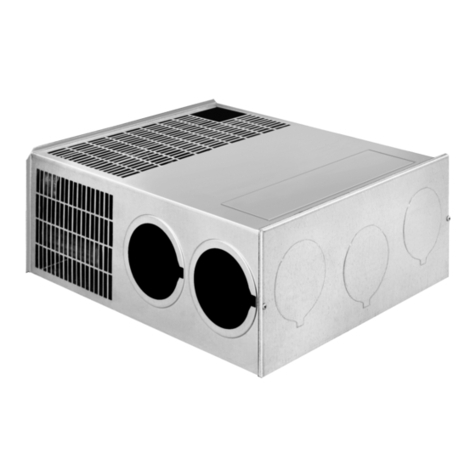
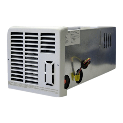
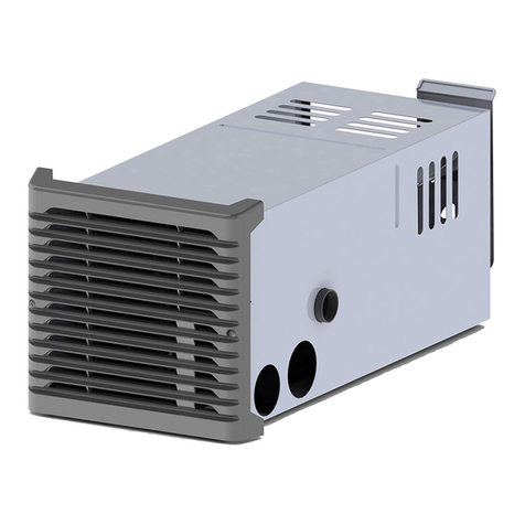
IMPORTANT: If this furnace is to be connected to a common duct system also
servinga cooling unlt, a manual or
automatic
damper
IS
required to prevent any
coldcondltloned alr from circulating back ~ntothe furnace Coldair passlng over
thefurnacecombustion chamberdur~ng
theoperatlonofthecoollng
unitcanresult
inthe formation of condensation Inside the furnace combust~onchamber Th~s
condensat~onmay promote corrosion and premature failure of the combustion
chamber.
NOTE: These furnaces shall be installed sc the
electrical
components are
protectedfrom water.
These furnaces are design certif~edfor propane1LP gas only. Do not attempt to
convert to natural gas.
Gas supply pressure for purposes of lnput adjustment.
Minimum
-
11" W.C.' Maximum
-
13" W C
'
(W.C.'
-
Water Column)
In the U.S.A.. the installation of the furnace must be ~naccordance with local
codesand regulat~ons.Inthe absence of local codes and regulations, referto the
latestedition of.
1.
Standardfor RecreationalVehicles ANSl A-119.2lNFPA 501C.
2. Nat~onalFuel Gas Code ANSl 2223.1
3. Furnacemust be electrically grounded ~naccordancewith the latest edition of
the National Electrical CodeANSIINFPA No. 70.
InCanada,the furnace must be installed in accordancewith.
I.
Standard CANICSA-Z24O Recreational Veh~cles.
2.
CSA Standard CANICSA-Z240.62-M86
Electrical
Requirements for
RecreationalVehicles.
3.
Standard CANICSA-Z240.4.2-M86 Installation Requirements for Propane
Appliances and Equipment in
Recreational
Vehicles.
4. CANICGA-B149 Installation Codes
5.
Any applicable local codes and regulations.
This unit is equipped with an electr~cigniter device that has an energy
consumptionof .lamp
@
12 volts D.C.
WARNING! Extensiontubes cannotbeused. Ifyou trytoextendthevent,
it
will result in improper installation which could cause unsafe furnace
operation.
Therearethree(3) methodsdescribed belowfor installingthefurnace.Regardless
of the method you choose,we require an openlng be providedin theexterior of
the trailer or motor home for free, unobstructed removal of the furnace. This
exterior, removable panel or wall section of the trailer or motor home must be a
minimumof 17-314 x 8.
It is important that adequate return air be provided to assure normalheatingand
operation of the furnace. Failure to provide the minimum return air will cause
erratic furnace cycling. Refer to the chart shown below for minimum return air
requirements.
Return Air Requirements
Model MinimumFree(unobstructed) Area
TABLE
I
SH-35
SH-42
Note: Return air must be from within the living area of the coach.
55 Sq. In.
142 Sq. In.'
'may
be reduced
to
88
sq
~n
mtn
~f
5
ducts are used
A. INSTALLATION DIRECTLY AGAINST OUTER PANELOF COACH
(See Figure I)(Panel supplied by installer)
Maximum wall thickness for this type installation is2".
1.
Locatethe furnace near lengthwise center of the coach.
2.
Choose a location for installation out of the way of wires, pipes, etc.. which
mightinterferewith the installation. Adhere to the minimum clearances from the
cabinet to combustible construction as listed in Table 2. Refer to Figure 3 for
illustrationof furnace clearances.
3.
When an applianceis installed directlyon carpeting, tile or other combustible
material, other than wood flooring, the appliance shall be installed on a metal or
wood panel extending the full width and depth of the appliance. If preferred, the
carpeting,tile or combustible materials, otherthanwood maybe cutaway the full
length and depth of the appliance plus the appliance minimum clearances to
combustibles. (See Table 2.)
4. Cut anopening throughthe inner wall. Thlswill allow the rear of the furnace to
be installed against the outer panel of the coach.
5.
Locatecenter lines for exhaust and intake, as shown in Figure 1
6.
Cut two 2-114" diameter holes through the outer panel of the coach. (See
Flgure 1
.)
7.
Put furnace in place, making sure that rear of the furnace cabinet is as close
to outer panelof the coachas possible and still assure proper vent tube overlap.
(See InstallingVent Assembly.)
8.
Using the two #I0x 314 stainless screws provided,fasten furnace cabinet to
floor of coach through the holes provided inthe furnace cabinet. (See Figure 4.)
9.
Be sure furnace is secured within furnace cabinet. (See Figure4.)
10.
Install vent assembly. (See instructions for installing vent.)
B. INSTALLATION FLUSH WITH INNER WALL OF COACH
(See Figure2) (Exterior panel supplied by installer)
Maximum wall thickness for this type installation is
2".
I.
Locatethe furnacenear lengthwise center of the coach.
2. Choose a location for installation out of the way of wires, pipes, etc, which
m~ghtinterfere wlth the installation. Adhere to the minimum clearances from
cabinet to combustible construction as l~stedin Table 2. Refer to Figure 3 for
illustration of furnace clearances
3. When an appliance is installed directly on carpetlng, tlle or other combustible
material,other than wood flooring, the appliance shall be installed on a metal or
wood panel extendingthe full wldth and depth of the appliance. If preferred, the
carpetlng,tileor combustible materials,other thanwood maybecutaway the full
length and depth of the appliance plus the appliance minimum clearances to
combustible (See Table 2
)
4. Locate center lines for exhaust and intake tubes as shown in Flgure 1
5.
Cuttwo 2-314"diameter holes throughthe removablewall sect~on.(SeeF~gure
2.)
6.
Put furnace in place, making sure that rear of furnace cabinet is as close to
inner wall section of the coach as possible and still assure proper vent tube
overlap. (See InstallingVent Assembly.)
7. Using the two #10 x 314 stainless screws provided, fasten furnace cabinet to
floor of coach through the holes provided In the furnace cabinet. (See Figure 4.)
8.
Be sure furnace is securedwithin furnace cabinet (See Figure4.)
9.
Installvent assembly. (See instructions for installing vent.)
C. INSTALLATION USING THE FURNACE ACCESS DOOR SUPPLIED BY
SUBURBAN (See Figure4)
Maximum wall thickness for this type installation is
2".
I.
Locatethe furnace near lengthwise center of coach.
2.
Choose a location for installation out of the way of wires, pipes, etc.,which
might interferewith the installation. Adhere to the minimum clearances from the
cabinet to combustible construction as listed in Table 2. Refer to Figure 3 for
illustration of furnace clearances.
3. When an appliance is installed directly on carpeting, tile or other combustible
material, other than wood flooring, the appliance shall be installed on a metal or
wood panel extendingthe full width and depth of the appliance. If preferred,the
carpeting, tile or combustible maters, other than wood may be cut away the full
length and depth of the appliance plus the appliance minimum clearances to
combustibles. (See Table 2.)
4. After furnacelocationhas beendetermined, cut anopening 18-7/32x10-1132"
through the inner coach wall and the outer wall (skin) of the coach.
5.
Caulk around opening as illustrated. Apply generously. The purpose of the
caulking isto seal the back side ofthe door frame and the coach skinwater tight.
6.
Secureframetoouterwall(skin)throughthe holesinthe frame.Screwsshould
be used. (See Figure4.) NOTE: Do not place screws into the holes required for
mountingthe door.
7. Slide furnacein place. The back ofthe furnace should be installedagainst or
as close as possible to the flange on the door frame. (See illustration.) The
furnace must maintain 112" overlap on the intake and 1-114 overlap on the
exhaust.
8.
Using the two #I0x 314 stainless screws provided, fasten furnace cabinet to
floor of coach through the holes provided in the furnace cabinet. (See Figure 4.)
9.
Be sure furnace is secured within furnace cabinet. (See Figure 4.)
10.
Position furnace access door over the frame. Secure the door to the coach
skin. Besure the coach skin isof sufficient strengthto keep furnaceaccessdoor
in place and insure a tight seal. It may be necessary to build a wood or metal
framearoundtheopeninginorderto provideadequatestrengthfor securingdoor.
CAUTION: The screws provided with the door may not be of sufficient
lengthand size for allapplications and itmay be necessaryforthe installer
tosubstitute screws inorder toadequately securethefurnace access door.
11. Installvent assembly.(See instructions for installing vent.)
Left Right Exhaust and
Model Front Side Side Top Bottom Back IntakeTube
SH-35 1" 1" 1" 1"
0 0
318"
SH-42 1"
2"
2"
1"
0
0"
3/RV
-NOTE-
0" MEANS TO SPACER BUMPS
CLEARANCE FROM DUCTS TO
COMBUSTIBLE MATERIAL
-
114" (See Figure3)
TABLE
2
INSTALLINGVENT ASSEMBLY
The vent outlet must be installedso it is in the same atmospheric pressurezone
as thecombustion airintake.Theexhaustandintaketubes mustbeinstalledfrom
the outside. pass through the RV skin and slide onto the furnace exhaust and
intake
WARNING! Donotalterthe vent assembly suppliedwiththisfurnace. Any
modificationswillresultinimproperinstallationwhichcouldcauseunsafe
furnace operation.
CAUTION! Combustionairmustnotbedrawnfromthe livingarea. All air for
combustionmustbedrawnfromtheoutside atmosphere. Allexhaustgases
mustbe vented tothe outside atmosphere
-
never insidetheRV. Therefore,
it
isessentialto insure that the vent cap and tube assemblies are properly
installed.

