Suburban Dynaline 3 Quick start guide

Suburban Dynaline 3 A&E Manual 12/2016 Rev.1
1
Ideal for Hotels/Motels,
Apartments and Senior Housing
•Four BTU/h Capacities
•12 - 20 MBTU Gas Heat
•Low Heating Amp Draw
•R-410A Refrigerant
ARCHITECT’S AND ENGINEER’S MANUAL
A Combination Gas Heating/Electric Cooling System
Designed to Serve an Individual Room or Zone
Dynaline
™3

Suburban Dynaline 3 A&E Manual 12/2016 Rev.1 2
Match Heating and Cooling Capacity to Your Project
with These Four Dynaline™3 Models:
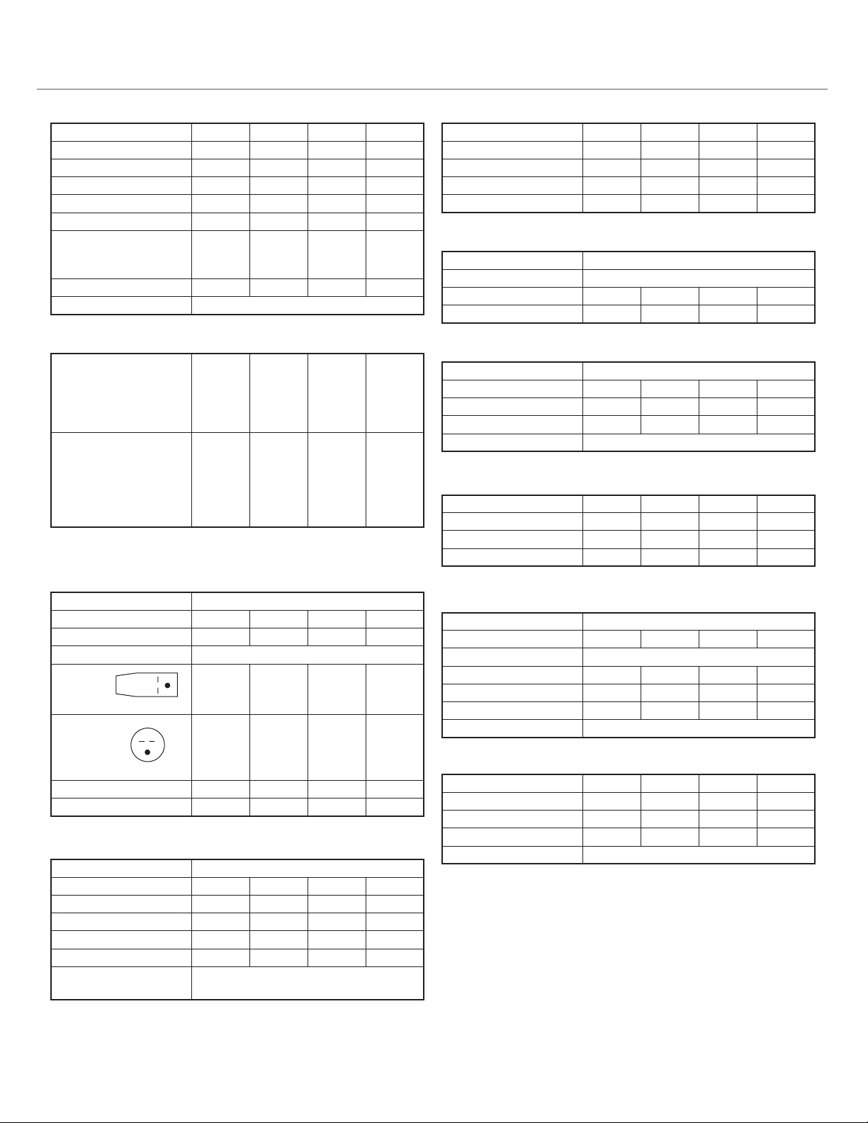
Model DL3-0712, with 7600 BTU/h cooling and 12,000 BTU/h gas heating
input, is ideal for small rooms or other applications that require zone
comfort control.
Model DL3-0912, with 9500 BTU/h cooling and 12,000 BTU/h gas heating
input, is ideal for hotels, motels, schools and nursing homes, or other
applications requiring zone comfort control.
Model DL3-1220 is for areas, such as, apartments and offices, with
11,500 BTU/h cooling and 18,000 BTU/h heating input.
Model DL3-1622 is for larger areas, such as, multi-family housing units, with
15,000 BTU/h cooling and 20,000 BTU/h heating input.
Economical Gas Heat
The unique Suburban Dynaline 3 provides high-efficiency gas heat in a zone
control heating and cooling unit. Clean gas heat is without equal for
economy and comfort. There is none of the “indoor wind chill”
that a heat pump creates. Compressor noise during the heating cycle is
eliminated, too. And, because Dynaline 3’s air discharge is much warmer
than a heat pump’s discharge, indoor temperatures reach a comfort level
much faster. The compressor operates only during the cooling cycle unlike
noisy heat pumps, thus extending the life of the compressor.
Savings for Builders
Dynaline 3’s space-saving, self-contained design eliminates most needs for
ductwork, water pipes, water towers, high-capacity standby generators and
rooftop equipment rooms. Dynaline 3 also frees architects and engineers
from the design constraints of central systems.
Safe
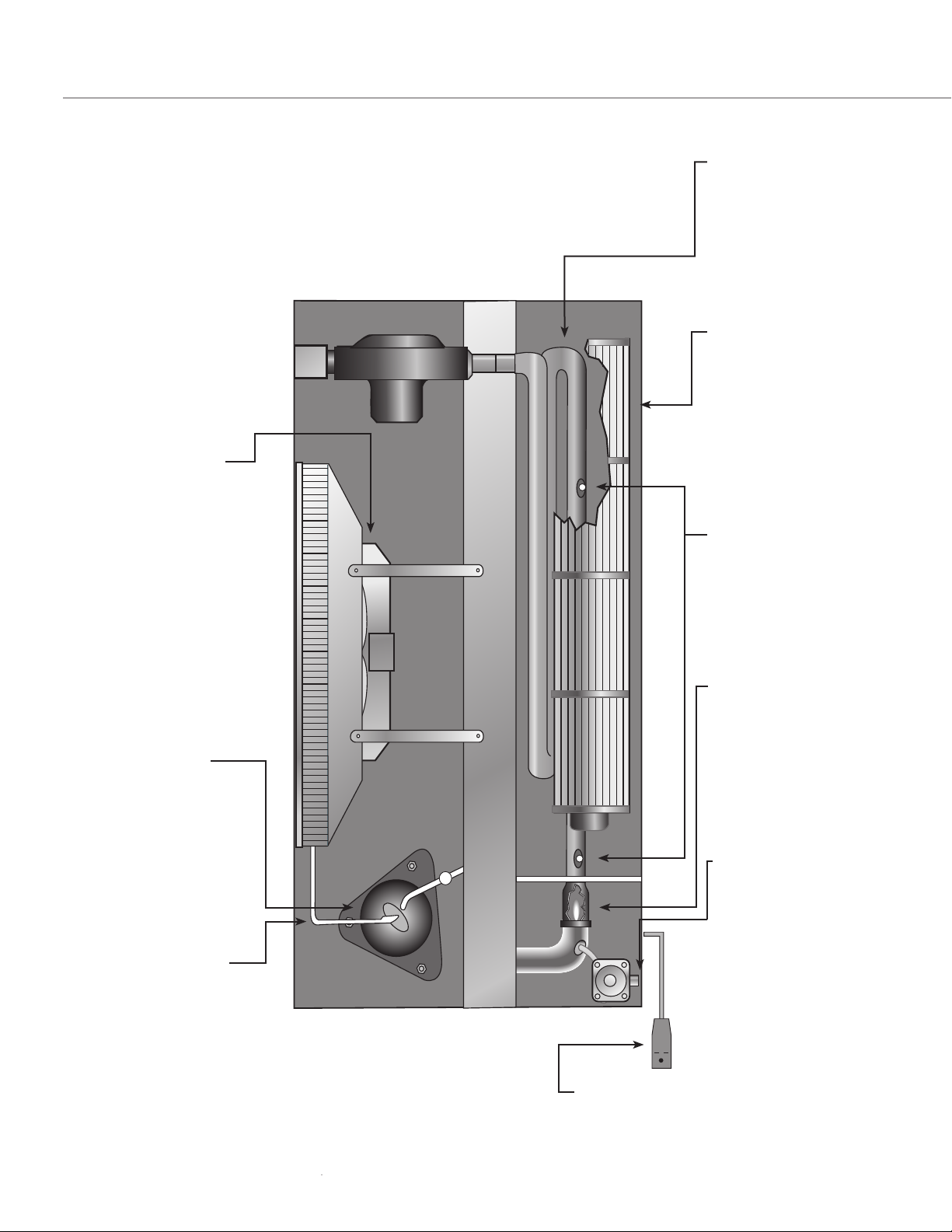
Dynaline 3’s sealed combustion furnace draws outside air through the heat
exchanger under negative pressure, and vents the products of combustion
directly to the outside atmosphere. Solid-state, electronic, hot surface
ignition (HSI) with no open flame is the modern alternative to pilot lights.
HSI increases energy conservation while ensuring safety.
Easy to Install and Service
Gas (LP or Natural) connections may be inside or outside the room.
Dynaline 3’s standard 42" x 16" wall sleeve makes it the right choice
for new construction or replacement applications. There is no need to
redesign an existing wall opening – just remove the old unit/sleeve and
replace with Dynaline 3.
Dynaline 3 combines a self-diagnostic control system, with a slide-out
chassis and removable electrostatic air filter (constructed of washable media)
for enhanced serviceability and easy maintenance.
INTRODUCTION
Dynaline™3 Packaged Terminal
Air Conditioner (PTAC) combines
the conventional features of
compact zone control systems with
the benefits of economical gas
heating. It provides year-round
comfort control for hotels, motels,
apartments, dormitories, shops,
nursing homes, assisted living
centers, satellite offices, room
additions and other applications
that require economical heating
and cooling. Specify Dynaline 3 for
new construction, or as the best
replacement for electric resistance
or heat pump units.
Each Dynaline 3 chassis has
individual controls – ideal for rooms
not occupied during vacancies,
holidays, weekends or nights.
Built-in, digital, touch pad heating
& cooling thermostat and fan
controls are standard, plus all units
have the flexibility to convert to a
wall thermostat control, or
interface into an energy
management system.
The greater the number of annual
heating degree days for a particular
locale, the more money Dynaline 3
can save in operating costs.
The Surburban Difference
Suburban developed the first gas-fired package terminal air conditioner (PTAC) in 1985.
Now in its third generation design, Suburban is a leading supplier to the senior housing
industry as well as other small commercial markets.

Suburban Dynaline 3 A&E Manual 12/2016 Rev.1
3
Operating Cost Analysis . . . . . . . . . . . . . . . . . . . . . . . . . . . . . . . . . . . . . . . . . . .4-5
Dynaline™3 Features ..............................................6-7
Dynaline 3 Specifications .......................................... 8
Suggested Bid Specifications .....................................9-10
Installing Dynaline 3 ...........................................11-12
General Information .............................................11
Location Considerations..........................................11
Framing ........................................................12
Knockdown Wall Sleeve ........................................... 13
Installing the Wall Sleeve .........................................13
Installing the Chassis .........................................14-16
Installation Data .............................................. 17-30
Making Gas Connections ........................................17
Installing Rear Gas Connection ...................................18
Air Discharge Package .........................................19-21
Air Discharge Connector .........................................21
Leveling Legs ....................................................22
Decorative Base..................................................22
Energy Management System ......................................22
Optional Drain Kit ..............................................23
Exterior Grille Styles .............................................23
Standard ....................................................23
Architectural ................................................23
Optional 2-PSIG Regulator .......................................24
Electrical Connections and Wiring .............................25-29
Unit Controls and Functions ...................................... 30
Operating Instructions – Built-in Thermostat .....................31-32
Operating Instructions – Remote Thermostat .................... 32-33
Operating Tips ................................................... 33
Accessory Description Review ..................................... 34
Dynaline 3 Airflow ............................................... 35
Suburban Limited Warranty .....................................36-37
Dynaline 3 PTAC Features and Benefits .......................... 38-39
Hotels/Motels
Individual room control.
Energy management interface.
Nursing, Assisted Living
Retirement Homes
Low heating amp draw
enables downsizing of standby
generator. Warm gas heat
improves tenant comfort.
Apartments/
Modular Housing
Gas heat/electric cooling in
one package. Air discharge
kit available for conditioning two
zones.
Classrooms/Offices
Easy to install. Two units can be
staged for economical operation.
This manual provides architects
and engineers with information
to select and design a zone comfort
control system using Suburban’s
Dynaline™3 Gas PTAC units. Proper
application of the equipment will
ensure satisfactory performance
over a wide range of operating
conditions. Gas PTACs are designed
for through-the-wall installations
in nursing homes, schools,
apartments, hotels/motels and
add-on rooms, or retrofit
zone control.
APPLICATION
CONSIDERATIONS
THE INSIDE STORY

Suburban Dynaline 3 A&E Manual 12/2016 Rev.1 4
Location: Northeast Midwest Mountain West Canada
Dynaline 3 $327.04 $338.81 $347.88 $151.40
Heat Pump $1,154.17 $389.63 $510.82 $896.94
Electric Heat $2,026.40 $731.48 $1,003.63 $1,455.60
The Suburban Dynaline 3 provides lower annualized operating costs,
in most locales in the United States and Canada, compared to packaged ter-
minal heat pumps and electric heat PTAC’s. The projected savings are depen-
dent on the cost of natural gas and the cost of electricity for each specific
locale.
Utilizing BIN Hour temperature data*, the following table provides
representative examples of costs to operate one PTAC for one year.
Suburban will gladly prepare a BIN Hour Cost Analysis for your location. For
more information, please contact the Suburban Sales/Marketing Department
at 423-775-2131, or contact your local Suburban Representative. To find your
local Suburban Representative, simply go to our website at www.suburban-
manufacturing.com and click “Find a rep”.
OPERATING COST ANALYSIS
Figure 1
*BIN Hours are the number of
hours of operation per year at the
mid-point temperature
specific to a geographical
location. The BIN Hours are
derived from historical
weather data.

Suburban Dynaline 3 A&E Manual 12/2016 Rev.1
5
Average unit cost of energy for
residential energy sources 2013
TYPE COST
Electricity 12.1¢ / kwh
Nat. gas $0.987 / therm
No. 2 heat oil $3.969 / gallon
Propane $2.69 / gallon
1 kwh = 3,412 BTU
1 therm = 100,000 BTU
1 gallon oil = 138,690 BTU
1 gallon propane = 91,333 BTU
Energy Information Agency
Table 2
Suburban Gas Heating and Electric Cooling
will save money in the long run.
The Suburban Dynaline™3 is a Packaged Terminal Air Conditioner
(PTAC) that combines economical gas heating and high-efficiency
electric cooling in one compact unit for zone temperature room-by-
room control. By comparing the operating costs of Dynaline 3 to
heat pumps or electric resistance heat, a savings of hundreds of dol-
lars per room every year can be achieved.
The Dynaline
™3 Difference
* Bin Hours are the number of hours of operation per year at the mid-point temperature specific to a geographical
location. The BIN hours are derived from historical weather data.
For example, at a location with 7,023 heating BIN hours,
such as Syracuse, NY, with a 2º design temperature, the cost to
heat with Dynaline 3 can save 80% in utility costs compared to
electric resistance. When compared to heat pumps, Dynaline 3
can save 66%. For a building with 60 PTACs, Dynaline 3 can
save over $77,000 in utility costs in one year!
Annual Annual
heating cost heating cost
Kw Hours per room for 60 rooms
Electric Heat 10,555 $1,600.23 $96,013.80
Heat Pump 5,912 $896.23 $53,773.80
Therms
Gas Heat 455 $306.90 $18,414.00
Location Example Syracuse, NY
Heating BIN hours 7,023
Heat load 13,000
Outside design temperature 2º
Inside design temperature 70º
Number of rooms 60
Heating correction factor 0.66
Cost of electricity $0.1516/
kW hours
Cost of gas $0.5637/
THERMS
HEAT
PUMP DYNALINE 3
Dynaline
saves
80%
Dynaline
saves
66%
Annual
Cost of
$307
Annual
Cost of
$1,600
Annual
Cost of
$896
ELECTRIC
HEAT
$1600 -
$1000 -
$750 -
$500 -
$250 -
$100 -

Suburban Dynaline 3 A&E Manual 12/2016 Rev.1 6
DYNALINE™3 FEATURES
TOP VIEW
De-ice control:
Low temperature cut-out
control protects compressor by
sensing freeze-up conditions
on the evaporator coil.
Electrical components:
Located on the indoor side
of the wall, they
are protected from the
weather and easily accessed
for service.
Attractive stamped
aluminum or
architectural-style
exterior grilles:
Custom finished
architectural grilles are
available to match your
building’s decor.
Condensate removal:
Condenser fan vaporizes
condensate from chassis
bottom and expels vapor
on the condenser coil.
This accelerates the
evaporation process.
Positive drain kit is
also available.
Air vent:
The manually-operated
lever allows entry of
70 CFM of outside air
into the conditioned space.
Rotary compressor:
Reliable, efficient and
quiet-running design
has a longer life
expectancy than heat
pump compressors.
The Dynaline™3 gas
PTAC does not use
the compressor during
heating cycles.
High Pressure Switch:
Protects the compressor
in unlikely event of
condenser fan failure.
Weather seals:
Seals the chassis to the
wall case, preventing
infiltration of air, water
and contaminants into
the conditioned area.
Electrical components:
Located on the indoor side
of the wall, they
are protected from the
weather and easily accessed
for service.
Sealed
combustion furnace:
Uses only outside air for
combustion. Hot
exhaust routes through
unit for maximum heat
exchange before exiting
outside.
Tangential
blower wheel:
Spans the length of the
heating chamber and
evaporator coil. Air
flow is uniform over
system components,
enhancing air
distribution and
system efficiency.
High limit:
Protect appliance by
turning gas off if, for
any reason, the
heating section
approaches an unsafe
temperature level.
Ignition:
An electronically
controlled Hot Surface
Ignitor, lights the burn-
er without
standing pilot lights.
Gas is conserved and
safety is ensured.
Gas connections:
Can be made inside or
outside, to suit design
or code requirements.
Available for Natural
gas or Propane.
A 2-PSIG regulator
accessory is available
(Natural gas only).
Control functions:
Top mounted for easy access. Include digital
touch pad-type heating/cooling thermostat,
and digital touch pad-type control for selecting
heating, cooling and manual fan settings.
Figure 2
Electrical connections:
Pigtail with leakage current detector
interruptor (supplied), or field direct
wire, to suit design or code requirements.

Suburban Dynaline 3 A&E Manual 12/2016 Rev.1
7
40
14
9
—
32
21
14
7
—
8
1
—
16
7
25
—
32
42
7
14
42
16
16
42
11
—
16
40
5
—
8
3
—
8
14
3
—
4
Copper and aluminum
evaporator and
condenser coils:
For extended life and
ease of repair. Coils
use seamless copper
tubing, mechanically
expanded into
aluminum plate fins.
Compressor lock-out:
Standard design
provides means of lock-
ing out A/C
compressor when
standby power
generator is operating.
Electronic control
board has 24V input
terminals to receive
lock-out signal.
Room air discharge:
Attractive, durable
grille constructed of
extruded aluminum,
52° off vertical air
discharge pattern.
Return air filter:
No tools are needed to
install or remove the
permanent electrostatic
filter constructed of
washable media.
END VIEW (LH)
UNIT WALL SLEEVE DIMENSIONS
Figure 4
Figure 3
Specifications subject to change without notice.

Suburban Dynaline 3 A&E Manual 12/2016 Rev.1 8
SPECIFICATIONS DYNALINE™3 SERIES
General Data
DL3-1622 DL3-1220 DL3-091 DL3-0712
Rated heating input (BTU/h) 20,000 18,000 12,000 12,000
Rated heating output (BTU/h) 16,000 14,580 9,840 9,840
Steady state efficiency 80% 81% 82% 82%
Rated cooling capacity (BTU/h) 15,000 11,500 9,500 7,600
Sensible/Latent cooling 65/35 65/35 69/31 65/35
EER 9.5 10.4 11.2 11.6
Rated air flow: fan only (CFM)
Hi cool/low cool (CFM)
Hi heat/low heat (CFM)
340
400/330
420/340
300
390/300
410/300
260
300/250
320/260
260
300/250
320/260
Weight (Lbs.) 185 180 180 180
Cabinet Color Champagne Beige
Minimum Installation Clearances
Outside:*
Rear to nearest obstruction
Top, sides to nearest
obstruction
Centerline vent to window
3 feet
0
9"
3 feet
0
9"
3 feet
0
9"
3 feet
0
9"
Inside:
Front to nearest obstruction
Sides to nearest obstruction
Bottom to floor
(for return air)
Cabinet top to ceiling
12"**
1"
0
12"
12"**
1"
0
12"
12"**
1"
0
12"
12"**
1"
0
12"
* Clearance to ground should be noted (see installation manual).
** Obstruction must be removable for service of unit.
Electrical Data
Volts/Phase/Cycle 208/230-1-60
Min. wire size (Copper) #14 AWG #14 AWG #14 AWG #14 AWG
Protection-Fused 2-15 amp 2-15 amp 2-15 amp 2-15 amp
Protection-Circuit (HACR type) Dual - 15 amp
Unit Plug:
Amps
NEMA Rating
15 amp
6-15 P
15 amp
6-15 P
15 amp
6-15 P
15 amp
6-15 P
Receptacle:
Type
Amps
NEMA Rating
Tandem
15 amp
6-15 R
Tandem
15 amp
6-15 R
Tandem
15 amp
6-15 R
Tandem
15 amp
6-15 R
Total amps cooling/heating 7.5/1.2 5.1/1.0 3.8/1.0 3.3/1.0
Total watts cooling/heating 1550/260 1125/150 855/150 675/150
Compressor
Type Hermetic Rotary
Refrigerant type (HCFC) R410-A R410-A R410-A R410-A
Refrigerant charge 36 oz. 32 oz. 26 oz. 28 oz.
Rated Load amps 6.6 5.1 3.9 2.9
Locked rotor Amps 32 25 22 15
Rated capacity (BTU/h) 14,100 10,300 8,050 6,600
Compressor lock-out relay (Normally closed 24V)
5VA enrush - 4V constant
Specifications subject to change without notice.
Condenser Fan
DL3-1622 DL3-1220 DL3-091 DL3-0712
Fan blade diameter 12" 12" 12" 12"
Number of blades 4444
Pitch 25º 25º 25º 25º
Condenser fan motor RPM 1,500 1,500 1,500 1,500
Full load amps 0.5 0.5 0.5 0.5
Condenser Coil
Type Copper/Aluminum
Coil Area 364 sq. inches
Rows 3 3 3 3
Fins per inch 13 13 12 12
Evaporator Coil
Type Copper/Aluminum
Coil Area 260 sq. in. 260 sq. in. 234 sq. in. 234 sq. in.
Rows 3 3 3 3
Fins per inch 11 11 11 11
Refrigerant metering Capillary
Room Air Fan Motor
Speed 2 2 2 2
RPM high/low 1500/1250 1520/1400 1260/1130 1260/1130
Full load amps 0.7 0.5 0.3 0.3
Min. wire size (60º copper) #18 AWG #18 AWG #18 AWG #18 AWG
Gas Controls and General Data
Gas (specify) Natural or LP
Burners 1 1 1 1
Ignition system: Solid-state Hot surface
High limit (fixed) 220º 220º 220º 220º
Blocked flue switch 205º 200º 200º 200º
Gas connection size 3/8" IPS 3/8" IPS 3/8" IPS 3/8" IPS
Gas connection (LH) front or rear
Blower/Evaporator
Wheel diameter 4.53" 4.53" 4.375" 4.375"
Wheel width 26" 26" 26" 26"
Air vent-manual 70 CFM 70 CFM 70 CFM 70 CFM
Required filter (1 each)
8-1/4"x30-3/4" 6"x30-3/4" 6"x30-3/4" 6"x30-3/4"
Filter type Electrostatic/washable media

Suburban Dynaline 3 A&E Manual 12/2016 Rev.1
9
The supplier will provide packaged terminal gas heat/electric air
conditioner of the sizes and capacities shown on the schedule and listed
in the specifications. Each unit shall consist of a chassis, wall case/sleeve,
outside grille and room cabinet. Units shall be UL listed and/or
ETL design certified and shall be Suburban Manufacturing Company
DYNALINE™3 models, or equivalents. The units shall be located as shown on
the drawings.
Unit’s steady state efficiency shall be rated at 80% nominal and the EER
of the air conditioner shall not be less than ASHRAE 90.1 - 2010 standards.
Units shall be designed to operate on 208/230 volts, 60 Hz, single
phase power.
Unit dimensions shall not exceed 42" wide and 16" high without optional air
discharge package in place, and not more than 22-29/32" from face of room
cabinet to face of standard exterior grille.
Units shall be designed to operate on Natural or LP gas for the heating cycle.
CHASSIS:
Unit chassis shall be a standard product of the manufacturer and shall
be packed to prevent damages when reasonable care is exercised during
shipment. Warnings on packaging shall alert handlers to the hazards of
improper handling or stacking.
Chassis shall slide into a standard-sized wall case and, after installation
and testing, be ready to operate. Each chassis shall consist of the following
system and components:
• Refrigeration system constructed to isolate the hermetically sealed
rotary-type compressor from external vibration. The system shall
include copper/aluminum condenser and evaporator coils with
capillary refrigerant control.
• Air flow system consists of a two-speed room air motor (for Hi &
Low A/C and Hi & Low heat speeds) and a fan cycle switch to permit
continuous indoor fan operation. A separate condenser fan operates in
the A/C cycle only. The condenser fan, not operating in the heating
mode, eliminates the potential for exhaust gases to be drawn back and
freezing in the chassis compartment. The room air system incorporates
a tangential blower wheel for reduced noise and increased efficiency.
• Condenser coils, with not less than 13 fins per inch, and evaporator
coils, with not less than 11 fins per inch. Coils shall be constructed
of copper/aluminum and fins shall be bonded to tubes to prevent
electrolytic action.
• Indoor and outdoor airflow which match the coil capacity for efficient
transfer of heat. Design of the unit shall prevent water blow-off on the
indoor evaporator coil. Indoor supply air grille, constructed of extruded
aluminum, shall discharge air at 52 degrees off vertical pattern.
• Electrostatic return air filter, constructed of washable media, that installs
and removes without tools.
• Factory-installed, gas-fired heat exchanger with electronic controlled,
pilotless ignition system and a “draw-through” negative draft
combustion air system. Gas ignition shall occur by energizing hot
surface ignitor, which lights the burner on each thermostatically
controlled heating cycle. Heat exchanger shall be located in indoor
air stream so as not to be visible or accessible through indoor supply
air grille.
SUGGESTED BID SPECIFICATIONS
FOR PRODUCT
AND APPLICATION

Suburban Dynaline 3 A&E Manual 12/2016 Rev.1 10
• Touch pad-type digital control for selecting temperature set point,
heating, cooling and manual fan operation. Control system to
incorporate computerized self-diagnostics to facilitate troubleshooting.
• Positive closing fresh air damper, located within the chassis.
An accessible manual control shall operate the damper.
• Compressor “lock-out” interface with standby emergency
power generator.
WALL CASE:
Wall case shall be constructed of 18-gauge galvanized and shall have a
protective baked-on enamel finish. Base pan shall be 18-gauge galvanized.
Cases shall be installed through exterior walls where shown on the plans
and shall be level from side to side and slope 1/4" from front to rear to ensure
proper operation of condensate system. Case shall be secured to
the wall at both sides as shown in installation instructions. In no instance
shall fasteners be used through the base pan so as to protect the water
integrity of the base pan.
OUTSIDE GRILLE:
Special grilles to be supplied by others must be submitted to the PTAC
manufacturer for feasibility and air flow characteristics.
ROOM CABINET:
Each room chassis shall be equipped with a removable, wrap-around
room cabinet constructed of 20-gauge galvanized steel with a protective
baked-on enamel finish similar to the wall case.
GAS TYPE:
Natural gas units shall be equipped with a gas valve having a built-in
regulator set to operate at the gas inlet supply pressure, minimum 5" W.C.,
maximum 7" W.C. Units burning LP gas shall be equipped with a gas valve
having a built-in regulator set to operate at gas inlet supply pressures of 11"
W.C. minimum and 13" W.C. maximum.
SERVICE:
Bidders shall submit complete information regarding service availability,
including address(es) and phone number(s), along with complete
information of manufacturer address and phone number to cover service
information pertinent to installed equipment.
RESPONSIBILITY FOR INSTALLATION,
START-UP, TESTING, DEMONSTRATION:
Units shall be installed in full accordance to the manufacturer’s
recommendation. The manufacturer shall not be liable for unit failure
resulting from improper installation, which invalidates the warranty.
Bidders shall specify their responsibilities for the initial starting of units,
performing necessary tests and adjustments to place units in proper
operating condition and demonstrating heating and cooling operations
to the owner or the owner’s representative.
WARRANTY:
There shall be a one-year limited warranty on parts and labor and a
five-year limited warranty on the compressor and heat exchanger.
SUGGESTED BID SPECIFICATIONS
FOR PRODUCT
AND APPLICATION

Suburban Dynaline 3 A&E Manual 12/2016 Rev.1
11
Suburban Dynaline™3 PTAC units are self-contained gas heating/electric
cooling systems for through-the-wall installations in hotels, motels,
hospitals, nursing homes, assisted living centers, add-on rooms, apartments,
shops, small offices and other applications. Dynaline 3 models offer:
• Energy-efficient operation • Application flexibility
• Reliable, durable construction • Ease of installation
• Ease of service and maintenance • Quiet operation
Suburban Dynaline 3 models are certified by ETL as gas-fired packaged
terminal air conditioners. Dynaline 3 complies with the latest edition of
American National Standard Z21.86/ETL 2.32 and UL 484. Dynaline 3 is
designed for use with Natural gas or Propane gas only.
Each Dynaline 3 unit is carefully packed in a container to withstand the load
conditions encountered in normal transit and handling. If inspection
reveals any damages, do not install the unit. Notify the transportation
company immediately, and file a damage claim.
Dynaline units are designed to be installed in residential homes and
commercial buildings with a minimum wall thickness of 1" and a
maximum wall thickness of 14-1/2" when using the standard wall
sleeve. (Maximum wall thickness cannot exceed 12-5/8" if rear gas
hook-up is to be used.) Units must be installed so that the rear portion
is vented to the outside atmosphere. Venting systems of the units must
not be altered.
In addition to being located along the outside wall of a room, the unit
should be installed where it can effectively circulate air into the room.
Generally, the best location is midway along the wall and away from a
stairwell, or other opening. Unit must not be located behind a door or
any location where a door could obstruct air circulation. Also, avoid
installing the unit in an alcove or recess that does not allow good
air circulation.
Note: Unit must not be used as a construction heater!
To ensure adequate service accessibility and proper operation, maintain
the minimum clearances shown in Table 3:
GENERAL
INFORMATION
INSTALLING DYNALINE™3
Minimum Operational Clearances
The following minimum outside clearance from rear grille must
be maintained:
• Rear of unit to nearest obstruction - 36"
• Top, Sides to nearest obstruction - 0"
Bottom of unit to obstruction and/or ground: This requirement is
determined by local climate and environmental conditions. The unit must be
above ground high enough to prevent snow, water, leaves or other obstruction
from blocking the rear of the unit.
The following minimum inside clearances from cabinet front must be maintained:
•
The flow of discharge air must not be obstructed for a minimum of 12"
• Side of cabinet to nearest obstruction – 1"
• Top of unit to ceiling – 12"
• Cabinet front to nearest obstruction – 12"*
• Bottom of wall sleeve front to finished floor – 0"
*Obstruction must be removable for service, otherwise minimum 36" required.
LOCATION
CONSIDERATION
Minimum Clearance to
Combustible Construction
Units are approved for 0"
clearance to combustible
construction top, sides,
and bottom. Front and
rear clearances not applicable
as there can be no
construction combustible
or non-combustible to the
front or rear of the opening.
Table 3

Suburban Dynaline 3 A&E Manual 12/2016 Rev.1 12
HEADER
(STEEL LINTEL IN BRICK CONSTRUCTION)
FINISHED FLOOR
SUB-FLOOR
NOTE: UNITS APPROVED FOR 0" CLEARANCE TO COMBUSTIBLE CONSTUCTIONS TOP, SIDES, AND BOTTOM. FRONT AND REAR CLEARANCE
NOT APPLICABLE AS THERE CAN BE NO CONSTRUCTION COMBUSTIBLE OR NON-COMBUSTIBLE TO THE FRONT OR REAR OF THE OPENING.
42
1
—
4
" MIN.
16
1
—
4
" MIN.
3
1
—
2
" MIN.
FRAMING In the United States and Canada, the installation must conform with local
codes. In the absence of local codes, US installations must conform with
the current National Fuel Gas Code ANSI Z223.1 and with the National
Electrical Code ANSI/NFPA No. 70, and Canadian installations must
conform with the current CANI-B149 installation code.
After selecting a location, inspect the wall and floor areas to determine
that there are no hidden electrical wires, piping, tubing, ducts, girders,
wall studs, etc., that might interfere with the proper installation and safe
operation of the unit and gas supply.
Dynaline™3 is designed to be installed through an exterior wall from
1" to 14-1/2" thick. To accommodate the unit’s dimensions (see Figure 5),
the wall opening must be framed as shown in Figures 6 & 7. For walls
thicker than 14-1/2", consult factory regarding available extended length
wall sleeves. The maximum wall thickness for rear gas hook-up is 12-5/8".
NOTE: Use conventional construction methods to frame the opening.
Do not use the wall sleeve as a lintel.
Figure 5
Figure 7
UNIT OVERALL DIMENSIONS
WALL SLEEVE FRAMING DIMENSIONS
FRONT GAS HOOK-UP
MIN.
1
—
4
MIN.
HEADER
(STEEL LINTEL IN BRICK CONSTRUCTION)
SURFACE OF FINISHED FLOOR
42 1
—
4"
16 "
Figure 6
WALL SLEEVE FRAMING DIMENSIONS
REAR GAS HOOK-UP

Suburban Dynaline 3 A&E Manual 12/2016 Rev.1
13
1. Unfold the sides of the wall sleeve and assemble the top, so that the
sides wedge between the top flange and the retaining angle. (See
Figure 8.) Apply 4 screws provided to secure top to the sides.
2. Cut an opening in the outside wall and frame to minimum opening.
(See Figures 6 & 7.)
3. Install wall sleeve into framed opening. Be sure that the bottom of wall
sleeve is resting firmly on the bottom framing member since the weight
of the unit rests solely on the bottom of the wall sleeve. Failure to
support the bottom of the wall sleeve could pull the sides away and
result in water leakage on the floor.
4. Secure the wall sleeve to the wall as shown in Figures 9 & 10. Be sure
wall sleeve has a 1/4" slope to the outside. Do not slope toward front!
To avoid water damage to the wall, do not put holes through the
bottom of the wall sleeve.
NOTE: If the unit is to be mounted flush with the exterior wall, wall
sleeve must protrude beyond the finished exterior wall a minimum of 1/4".
If rear gas connection, sleeve must extend beyond the finished exterior wall
surface 1-5/8”. (See Figures 9, 10, & 11.)
5. Trim around the wall sleeve with moulding or other suitable material.
(See Figures 9, 10, & 11.)
6. Install the grille with louvers angled in the downward position, as
shown in Figures 9, 10 & 11.
NOTE: Outside rear grille must be installed prior to installing chassis.
NOTE: Do not discard packing inside carton. It may be used as a
temporary cover for weather and construction protection. To cover the wall
sleeve opening, cut cardboard insert along the perforated line, fold and place
in rear of sleeve.
INSTALLING THE
WALL SLEEVE
KNOCKDOWN WALL SLEEVE
Figure 8

Suburban Dynaline 3 A&E Manual 12/2016 Rev.1 14
SLOPE DOWN TO THE OUTSIDE
SURFACE OF FINISHED
FLOOR OR TOP OF CARPET
MIN. (PROJECTION BEYOND EXTERIOR WALL)
Y"
X"
MOUNTING HOLES AND SCREWS
(BY INSTALLER.)
DO NOT PUT HOLES THROUGH
WALL SLEEVE BOTTOM!
REAR GRILLE
CAULK AROUND WALL SLEEVE
SURFACE OF FINISHED EXTERIOR WALL
Y" = - ( X" + )
SURFACE OF FINISHED INTERIOR WALL
CABINET FRONT
X" REPRESENTS EITHER THE
DIMENSION REQUIRED TO FLUSH
SLEEVE TO FINISHED TRIM OR
MOLDING, OR THE DISTANCE
SLEEVE PROJECTS INTO ROOM
BEYOND FINISHED INTERIOR
WALL.
NOTE: X" CAN BE 0" IF
SLEEVE IS FLUSH WITH
FINISHED INTERIOR WALL.
1
5
—
8
"
1
—
4
"
1
5
—
8
"
14
3
—
4
"
INSTALLING
THE CHASSIS
1. Slide chassis squarely into wall sleeve from inside and secure with four
(4) screws into flange on wall sleeve to ensure proper security.
2. Connect gas and electrical supply. (See pages 13, 14 and 20.)
3. Remote thermostat: Dynaline™3 chassis are supplied for standard
built-in control. To convert the standard chassis to function with remote
thermostat, connect the thermostat wiring (according to thermostat
manufacturer’s instructions) to the terminal block located on the
module board. Move the dip switch #1 on the module board to the
“ON” position. (See Figure 12.) Unit is capable of operating set-back
(5-wire) thermostat.
NOTE: Connecting remote thermostat overrides the built-in thermostat
and no digital read out will be displayed on the control panel. There is no
need to disconnect the chassis’ built-in thermostat.
4. To lock out the A/C compressor when the chassis is powered by
an emergency standby power generator, 24-volt lead wires from the
transformer (NOTE: Field supplied transformer to be powered by the
standby generator) must be connected to the 1/4" spade terminals on
the module board. (See Figure 27 for ladder diagram of typical standby
generator electric service.)
5. Install cabinet front.
Figure 9
WALL INSTALLATION
REAR GAS HOOK-UP

Suburban Dynaline 3 A&E Manual 12/2016 Rev.1
15
X" REPRESENTS EITHER THE
DIMENSION REQUIRED TO FLUSH
SLEEVE TO FINISHED TRIM OR
MOLDING, OR THE DISTANCE
SLEEVE PROJECTS INTO ROOM
BEYOND FINISHED INTERIOR
WALL.
NOTE: X" CAN BE 0"
IF SLEEVE IS FLUSH
WITH FINISHED
INTERIOR WALL.
SURFACE OF FINISHED INTERIOR WALL
CABINET FRONT
SLOPE DOWN TO THE OUTSIDE
MIN. (PROJECTION BEYOND EXTERIOR WALL)
MOUNTING HOLES AND SCREWS
(BY INSTALLER.)
DO NOT PUT HOLES THROUGH
WALL SLEEVE BOTTOM!
REAR GRILLE
CAULK AROUND WALL SLEEVE
SURFACE OF FINISHED EXTERIOR WALL
3 (MIN.)
2
1"
Y"
X"
Y" = 14 - ( X" + )
3"
4
1"
4
1"
4
1"
4
SURFACE OF FINISHED
FLOOR OR TOP OF CARPET
SLOPE DOWN TO THE OUTSIDE
SURFACE OF FINISHED
FLOOR OR TOP OF CARPET
MIN. (PROJECTION BEYOND WALL)
WALL SLEEVE ANGLES & SCREWS
(BY INSTALLER.)
DO NOT PUT HOLES THROUGH OR DRIVE
SCREWS INTO WALL SLEEVE BOTTOM!
CAULK AROUND WALL SLEEVE
WINDOW OR WALL
CABINET FRONT
WALL SLEEVE
(MAX.) LONG SCREWS FOR SECURING
ANGLES TO TOP & SIDES OF SLEEVE.
2 (MIN.) SUPPORTS
(BY INSTALLER)
REAR GRILLE
1"
2
3 (MIN.)
1"
21"
4
1"
4
Figure 10
Figure 11
WALL INSTALLATION
FRONT GAS HOOK-UP
WINDOW, CURTAIN WALL, OR
WALL PANEL INSTALLATION

Suburban Dynaline 3 A&E Manual 12/2016 Rev.1 16
Figure 12

Suburban Dynaline 3 A&E Manual 12/2016 Rev.1
17
Dynaline™3 chassis are factory equipped with a 3/8" NPT gas connection
located at the bottom left front corner. Gas piping used to make the gas
connection to the unit must be purchased locally. The size of the pipe should be
computed according to type of gas and length
of run. (See
Table 5
.)
See Figure
13 for location of gas connection on the chassis when installed into
the wall sleeve.
Table 5 gives a reasonably accurate size for the gas service line. The quantities in
the table are for cubic feet per hour. To convert BTU capacity to cubic feet, divide
total BTU load by the BTU value of the gas being used. The table is for Natural
gas only. To convert to Propane gas, multiply by .633.
The pressure drop caused by other gas appliances being served must be
considered. If the new line is a take-off from an existing line to another
appliance, pressure drop computation with the table must include the
demand of the other appliance.
Gas supply pressure for purposes of input adjustment
Minimum Maximum
Natural Gas 5" Water Column 7" Water Column
Propane Gas 11" Water Column 13" Water Column
Table 4
Length
of pipe 1/2 3/4 1 1-1/4 1-1/2
in feet
10 132 278 520 1,050 1,600
20 92 190 350 730 1,100
30 73 152 285 590 890
40 63 130 245 500 760
50 56 115 215 440 670
60 50 105 195 400 610
70 46 96 180 370 560
80 43 90 170 350 530
90 40 84 160 320 490
100 38 79 150 305 460
125 34 72 130 275 410
150 31 64 120 250 380
175 28 59 110 225 350
200 26 55 100 210 320
MAKING GAS
CONNECTIONS
Iron Pipe Sizes (IPS) Inches
INSTALLATION DATA
Table 5
Capacity of pipe of different
diameters and lengths in cubic
feet per hour with pressure drop
of 0.3 inches and specific gravity
of 0.60 inches.
All units are equipped with a valve having a built-in regulator. For units
burning Natural gas, the regulator is preset at 3.5" W.C. pressure. For units
burning LP gas, the regulator is preset at 10.5" W.C. pressure.
It is recommended that a shut-off valve be installed in the gas line to
the unit, and that a ground joint union also be installed.
NOTE: Manual shut-off valve to be supplied by installer.
A condensate trap should also be installed in the gas supply line as
close to the unit as possible.
To occasionally monitor the gas
supply pressure to the unit, install a
1/8" NPT plug tap for test gauge
connection immediately upstream
of the gas supply connection to the
unit. The unit must be disconnected
from the gas supply piping system
during any pressure testing of the
gas supply system at test pressures
equal to or greater than 1/2 PSIG.
Figure 13
Operating Pressure

Suburban Dynaline 3 A&E Manual 12/2016 Rev.1 18
INSTALLING REAR
GAS CONNECTION
WITH REAR GAS
HOOK-UP KIT
Dynaline™3 chassis are manufactured for front gas hook-up. The optional
rear gas hook-up kit can be used for field conversion of the chassis to a rear
gas hook-up at the RH side (facing back of the unit).
1. Remove cabinet front.
2. Remove brass street elbow from valve and replace it with the 3/8" NPT
x 3/8" flare elbow provided. Be sure to apply a thread compound
resistant to the action of liquefied petroleum (LP) gas and Natural gas
to the threads. NOTE: Flared portion of elbow must be pointing up.
Do not discard the elbow that was removed. It will be used later.
(See A, Figure 14.)
3. Remove the 1-1/8" plug from the firewall and replace it with the 1-1/8"
universal bushing provided. (See B, Figure 14.)
4. Using the two (2) 8-32 x 1/2 self tapping screws provided, secure hi-ear
elbow as illustrated. (See C, Figure 14.)
5. Insert gas inlet tube assembly. (See D, Figure 14) through bushing in
firewall. NOTE: The shortest end of the tube connects to main gas valve.
6. Secure tube assembly to elbows as illustrated. (See Figure 14.) Do not
apply thread compound to flare fittings.
7. Using silicone caulking, seal gas inlet tube assembly where it passes
through bushing. (See E, Figure 14.)
8. Install street elbow removed from valve in Step #2. Clean threads, and
apply new thread compound sealant. Secure street elbow to the 90°
hi-ear elbow that was attached to chassis in Step #4. Female threads
must be pointing down.
9. Install chassis into wall sleeve.
10. Chassis installation into wall case can now be completed by installing
nipple, union and shutoff valve (field supplied) in accordance with
local code.
11. Check all joints for gas leaks.
NOTE: Wall sleeve must extend beyond the finished exterior wall surface
1-5/8" minimum.

Suburban Dynaline 3 A&E Manual 12/2016 Rev.1
19
MAIN GAS VALVE
90ϒ BRASS ELBOW
3/8 MALE X 3/8 FLARE
FIREWALL
GAS INLET TUBE ASSEMBLY
90ϒ BRASS ELBOW
3/8 MALE X 3/8 FEMALE
NIPPLE
UNION
1" CLOSE
NIPPLE
MANUAL SHUT-OFF VALVE
ILLUSTRATION OF SUGGESTED METHOD FOR MAKING
GAS CONNECTION (FIELD SUPPLIED PARTS)
CAULKING
90ϒ HI-EAR ELBOW (3/8 NPT X 3/8 FLARE)
APPLY PIPE THREAD
COMPOUND HERE
APPLY PIPE THREAD
COMPOUND HERE
STREET ELBOW MUST
BE SECURED PRIOR
TO INSTALLING CHASSIS
INTO WALL SLEEVE
A
B
E
D
C
REMOVE PLUG BUTTON FROM FIREWALL
AND INSTALL 1-1/8" UNIVERSAL BUSHING
TWO OPTIONS OF
SUPPLYING
CONDITIONED
AIR TO AN
ADJOINING ROOM.
• Rectangular Front
• Air Discharge Package
The optional air discharge package allows heating and cooling of an
adjoining room. (Not for use with 0712 Model.) The adaptor is
preassembled for air discharge to the right but can easily be converted
for discharge to the left. The adaptor is 43-1/4" long with female
connection. The extension is 43-1/4" long with 1" male tapered flange.
If you wish to discharge the air to the left, remove the end cover from
the left end of the adaptor and secure it to the right end. Next, turn it
around so the flow of air will be directed toward the front. The grille on the
adaptor need not be removed. Air apportionment can range from
30% to 70% for the primary room and 70% to 30% for the secondary room.
(See Table 6.)
Discharge air is dependent on Dynaline 3 model selected, mode of
operation (heat or cool), and length of total air discharge application.
When additional length is required, a connector is used in conjunction with
the air discharge package. Up to two connectors can be placed
between the adaptor and the extension (DL3-1220 or DL3-1622 only).
Suburban recommends that chassis with air discharge packages be
controlled via remote control thermostats.
Figure 14

Suburban Dynaline 3 A&E Manual 12/2016 Rev.1 20
DL3-1220/DL3-1622 DL3-0912**
1* 2 3 3
HI LOW HI LOW HI LOW HI LOW
50/50 143/121 127/108 50/50 144/122 128/108 50/50 145/123 129/109 50/50 123/104 109/93
60/40 159/102 142/91 60/40 160/103 143/91 60/40 161/103 143/92 60/40 137/88 122/78
70/30 173/85 154/76 70/30 174/84 155/76 70/30 175/86 156/77 70/30 149/73 132/65
Installation when adaptor support brackets are mounted
to finished wall.
NOTE: Projection of wall sleeve into room cannot exceed 1-1/4".
1. Mount adaptor brackets to the wall as illustrated.
Installer to provide screws. (See Figure 17.)
2. Slide collar into position under the adaptor and secure
with the two (2) screws provided. (See Figure 16.)
3. If the required air flow direction is to the left, remove
the end cap and three (3) tinnermans from the left end
of the adaptor. Reinstall end cap and tinnermans to
the right end of the adaptor.
4. Remove the center section from the cabinet front
assembly. (See Figure 15.)If the center section is not
removed, you will be unable to open the cabinet
front once the collar and adaptor are installed.
Discard center section.
5. Remove the discharge air grille from the unit.
Retain the two (2) screws.
6. Place the adaptor and collar assembly into position
on the unit. Make sure the adaptor is resting on the
adaptor brackets – adjust brackets as needed!
7. Locate the hole in the adaptor bracket and mark the
underside of the adaptor at each end.
8. Remove adaptor and collar assembly from unit. At the
two (2) locations marked on the adaptor in Step #7,
drill a 7/64"-diameter hole (2 places).
9. Install adaptor and collar assembly on unit as
illustrated and secure with the two (2) screws retained
in Step #5. Also, secure the adaptor to the adaptor
brackets with the screws provided.
10. Install the extension (DL3-0912) or the connector(s)
and extension (DL3-1220 or DL3-1622 only) as
required. Installer must provide wall support brackets
for the connectors and extension.
11. Air Delivery: The air delivery baffle, located under the
discharge air grille in the adaptor, is factory positioned
to provide a 50/50 distribution of air into each zone.
By removing the baffle and cutting along the scored
line, 60% of the conditioned air will flow in the
primary zone. Removing the baffle results in a 70/30
split. (On model DL3-1622 you must remove the
baffle). For best results unit should be run on Hi only
when using discharge package.
CFM CHART (DRY COIL)
** DL3-0912 - 1 and 2
are N/A. There is only one
extension or connector
allowed for DL3-0912
INSTALLING AIR
DISCHARGE PACKAGE
Figure 16
Figure 15
* Max. length = 130" from adaptor.
1
2
3
A
A
A B
B
B
Table 6
This manual suits for next models
4
Table of contents
Other Suburban Heating System manuals
Popular Heating System manuals by other brands

Selkirk
Selkirk HE40 quick start guide

ISOPAD
ISOPAD Thermocoax IT-KDL Series operating instructions

Tecnosystemi
Tecnosystemi Apply HI-TECH PUR user manual

Airxcel
Airxcel Aqua-Hot 100 Series Service manual

Gebwell
Gebwell G-Power Installation, operation and maintenance manual

Daikin
Daikin REYQ8U7Y1B Installation and operation manual

Robur
Robur Gitie AHAY35/4 manual

Viessmann
Viessmann VITOTRONIC 200 operating instructions

Hotstart
Hotstart OCLE Installation & operation manual

Envirovent
Envirovent energiSava 325 Installation guide for engineer / installer

Lunos
Lunos LUNOMAT installation instructions

TyloHelo
TyloHelo BWT Installation and operation manual