Lennox VSCA Series User manual

1
INSTALLATION
INSTRUCTIONS
VRF SYSTEMS -- Floor Standing Indoor Units
508061-01
03/2020
THIS MANUAL MUST BE LEFT WITH THE OWNER FOR
FUTURE REFERENCE
Shipping and Packing List
General
Check the components for shipping damage. If you nd
any damage, immediately contact the last carrier.
Package 1 of 1 contains the following:
1 - Assembled indoor unit
4 - Foot bolts
1 - Receiver/Display panel
2 - Refrigerant piping insulation sleeves
1 - Resistor
2 - Brass are nut
1 - Controller Wiring harness
1 - Water level switch cable
1 - Installation manual
Optional accessories, purchased separately:
1 - Wired controller V0STAT55P-3 (19X69)
2 - Base (VSEA only)
2 - Support feet V8VSA001-3P (19X68)
VSCA Floor Standing Cased /
VSEA Floor Standing Exposed
The VSC Floor Standing Cased / VSE Floor Standing Ex-
posed non-ducted indoor units are matched with an outdoor
heat recovery or heat pump unit to create a VRF (variable
refrigerant ow) system that uses HFC-410A refrigerant.
Refer to the Product Specication bulletin (EHB) for the
proper use of these indoor units with specic heat pumps,
heat recovery units, mode switching devices, branch pipes,
line sets and controls.
These instructions are intended as a general guide and do
not supersede local codes in any way. Consult authorities
having jurisdiction before installation.
WARNING
!
Improper installation, adjustment, alteration, service
or maintenance can cause property damage, personal
injury or loss of life.
Installation and service must be performed by a li-
censed professional HVAC installer, service agency
or the gas supplier.
Failure to follow safety warnings and these instruc-
tions exactly could result in property damage, dan-
gerous operation, serious injury, or death.
Any additions, changes, or conversions required in
order for the appliance to satisfactorily meet the ap-
plication needs must be made by a licensed profes-
sional HVAC installer (or equivalent) using factory-
specied parts.
Do not use this system if any part has been under
water. A ood-damaged appliance is extremely dan-
gerous. Immediately call a licensed professional
HVAC service technician (or equivalent) to inspect
the system and to replace all controls and electrical
parts that have been wet, or to replace the system, if
deemed necessary.
The State of California has determined that this
product may contain or produce a chemical or
chemicals, in very low doses, which may cause
serious illness or death. It may also cause cancer,
birth defects, or reproductive harm.
CAUTION
!
As with any mechanical equipment, personal injury
can result from contact with sharp sheet metal edges.
Be careful when you handle this equipment.
©2020 Lennox Industries Inc. Dallas, Texas, USA
VRF

2
Model Number Identication
Safety Requirements
ELECTRICAL SHOCK, FIRE, OR EXPLOSION HAZARD.
Do not touch the unit or the controller if your hands are wet.
DO NOT spray water on the indoor unit for any reason.
Do not replace a fuse with a fuse of a dierent rating. Do not use a jumper wire to replace a fuse. Do not insert
your hands, tools or any other item into the air intake or air outlet at either the indoor or outdoor unit.
Do not allow children to operate the system.
WARNING
!
V SC A 012 H4 - 3 P
Brand/Family
V = Variable Refrigerant Flow (VRF)
Unit Type
SC = Floor Standing Cased Non-Ducted Indoor Models
SE = Floor Standing Exposed Non-Ducted Indoor Models
Major Design Sequence
A = 1st Generation
Cooling Eciency
H = High Eciency
Refrigerant Type
4 = R-410A
Controls Protocol
3 = Phase 3
Nominal Cooling Capacity - Btuh
007 = 7,000 Btuh
009 = 9,000 Btuh
012 = 12,000 Btuh
015 = 15,000 Btuh
018 = 18,000 Btuh
024 = 24,000 Btuh
Voltage
P = 208/230V-1 phase-60hz
System Piping
CAUTION
VRF system piping is customized for each installation.
The LVSS piping report is an engineered design that must
be followed. The piping diagram or diagrams included
within the LVSS report have been prepared based on
the information provided to the Lennox VRF applications
department.
When the indicated lengths change from the gures
stated within the report, it is imperative that prior to the
commencement of the refrigerant pipe work installation,
Lennox VRF applications department are informed of
these proposed changes.
Upon receipt of this new information the Lennox VRF
applications department will conrm any changes that
may be applicable to this installation. If changes are
required, a new piping diagram will be produced and will
supersede all other previously provided documents.
Failure to provide this information regarding changes
to the original design may lead to insucient capacity,
equipment failure, warranty being made void and the
refusal to commission the system.

3
Dimensions - VSCA Cased
Unit Model VSCA007, 009, 012 VSCA015 VSCA018 VSCA024
Inches MM Inches MM Inches MM Inches MM
A40-1/8 1019 48-7/8 1241 53-1/2 1359 53-1/2 1359
B19-1/2 495 19-1/2 495 23-1/4 591 23-1/4 591
C30 762 38-3/4 984 43-1/2 1105 43-1/2 1105
D14-3/4 375 14-3/4 375 15-3/8 391 15-3/8 391
RIGHT SIDE VIEW
LIQUID PIPE
GAS PIPE
C
TOP OF UNIT
AIR FLOW
BOTTOM OF UNIT
BOTTOM OF UNIT
TOP OF UNIT
5 (127) 1-7/8 (48)
D
LEFT SIDE VIEW
7-7/8 (200)
BACK VIEW
FRONT VIEW
RETURN
AIR OPENING
B
A
CONDENSATE
DRAIN
CONNECTION
AIR FLOW
SUPPLY
AIR OPENING

4
Shown with optional feet accessory
(Model #, Cat #).
LIQUID PIPE
GAS PIPE
AIR FLOW
AIR FLOW
RETURN
AIR OPENING
ELECTRICAL
CONTROL BO
X
CONDENSATE
DRAIN
CONNECTION
CONDENSATE
DRAIN
CONNECTION
ELECTRICAL
CONTROL BOX
FILTER
ACCESS
Dimensions - VSCA Cased

5
Dimensions - VSCE Exposed
Unit Model VSEA007, 009, 012 VSEA015 VSEA018 VSEA024
Inches MM Inches MM Inches MM Inches MM
C30 762 38-3/4 984 43-1/2 1105 43-1/2 1105
D14-3/4 375 14-3/4 375 15-3/8 391 15-3/8 391
G36 914 44-5/8 1133 49-3/8 1254 49-3/8 1254
H18-1/2 470 18-1/2 470 22-1/4 565 22-1/4 565
RIGHT SIDE VIEW
LIQUID PIPE
GAS PIPE
SUPPLY
AIR OPENING
TOP OF UNIT
AIR FLOW
BOTTOM OF UNIT
BOTTOM OF UNIT
TOP OF UNIT
LEFT SIDE VIEW
7-7/8 (200)
BACK VIEW
FRONT VIEW
RETURN
AIR OPENING
H
G
CONDENSATE
DRAIN
CONNECTION
AIR FLOW
CONDENSATE
DRAIN
CONNECTION
BOLT
HOLS
3-3/8 (79)
D
C

6
LIQUID PIPE
GAS PIPE
AIR FLOW
RETURN
AIR OPENING
ELECTRICAL
CONTROL BO
X
AIR FLOW
ELECTRICAL
CONTROL BOX
CONDENSATE
DRAIN
CONNECTION
CONDENSATE
DRAIN
CONNECTION
CONDENSAT
E
DRAIN
CONNECTION
FILTER
ACCESS
Dimensions - VSCE Exposed

7
Clearances
SIDE
24
(610)
BOTTOM
3-1/2 (89)
TOP
59 (1499)
SIDE
6
(152)
Optional Feet Accessory
V8VSA001-3P (19X68)
BACK
2 (51)
BOTTOM
3-1/2 (89)
SIDE
24
(610)
SIDE
6
(152)
TOP
59 (1499)
VSCA Floor Standing Cased Mounted on Wall
VSCA Floor Standing Cased with Optional Feet Accessory

8
Clearances
VSEA Floor Standing Cased Mounted on Wall
VSEA Floor Standing Exposed with Optional Feet Accessory
BOTTOM
3-1/2 (89)
SIDE
24
(610)
SIDE
6
(152)
TOP
59 (1499)
Base
Optional Feet Accessory
V8VSA001-3P (19X68)
BACK
2 (51)
SIDE
24
(610)
SIDE
6
(152)
TOP
59 (1499)
Base
BOTTOM
3-1/2 (89)

9
Unit Placement
In addition to clearances, the following items should be
considered:
WARNING
!
Use the provided and specied components when
installing equipment. Failure to do so may result in
unit falling, water leaking or electrical shocks, caus-
ing personal injury or equipment or property damage.
Check stability of wall, oor, or ceiling and unit
support. If support is not capable of carrying weight
of the unit, unit may fall causing personal injury or
equipment damage.
Consider the possibility of earthquakes in your
area when installing the equipment. If the unit is not
correctly secured, it may fall, causing personal injury
or equipment damage.
Safely dispose of packing materials, which include
nails, wood and other sharp objects, as well as plastic
wrapping. Children playing with plastic wrap or bags
risk the danger of suocation.
AVOID
Do not install the unit in the following locations:
• Areas exposed to petrochemicals or petrochemical
products
• Areas exposed to salt or other corrosive materials or
caustic gasses
• Areas exposed to extreme voltage variations (such as
factories
• Tightly enclosed areas that may impede service of the
unit
• Areas exposed to fossil fuels (such as oil or gas in
kitchens)
• Areas exposed to strong electromagnetic forces
• Areas exposed to acids or alkaline detergents (laundry
rooms)
DO:
• Locate the unit so that it is not exposed to direct sunlight
• Locate the indoor unit so that the room can be uniformly
cooled.
• Ensure the structural wall or oor can support the
weight of the unit.
• Select a location where condensate line will have the
shortest run to a suitable drain per local codes.
Installation
1. Locate a suitable position within the space where
maintenance access and supply air will not be restricted
or aected by obstacles. The minimum clearances are
given on Page 5.
CAUTION
!
Do not place items which may be damaged by water
under or around the indoor unit.
The unit should be installed at least 8 feet above the
oor (if possible) to ensure maximum performance
and comfort, when installed in the horizontal position
only.
• Allow sucient space around unit for proper operation
and maintenance (lter must able to be removed from
the front/bottom of the unit).
• Install unit a minimum of 3 feet away from any antenna,
power cord (line) radio, telephone, security system, or
intercom. Electrical interference and radio frequencies
from any of these sources may aect operation
• Be sure to instruct customers how to properly
operate the unit (especially maintenance of air lter,
and operation procedure) by having them carry out
operations themselves while looking at the manual
provided with the controller.
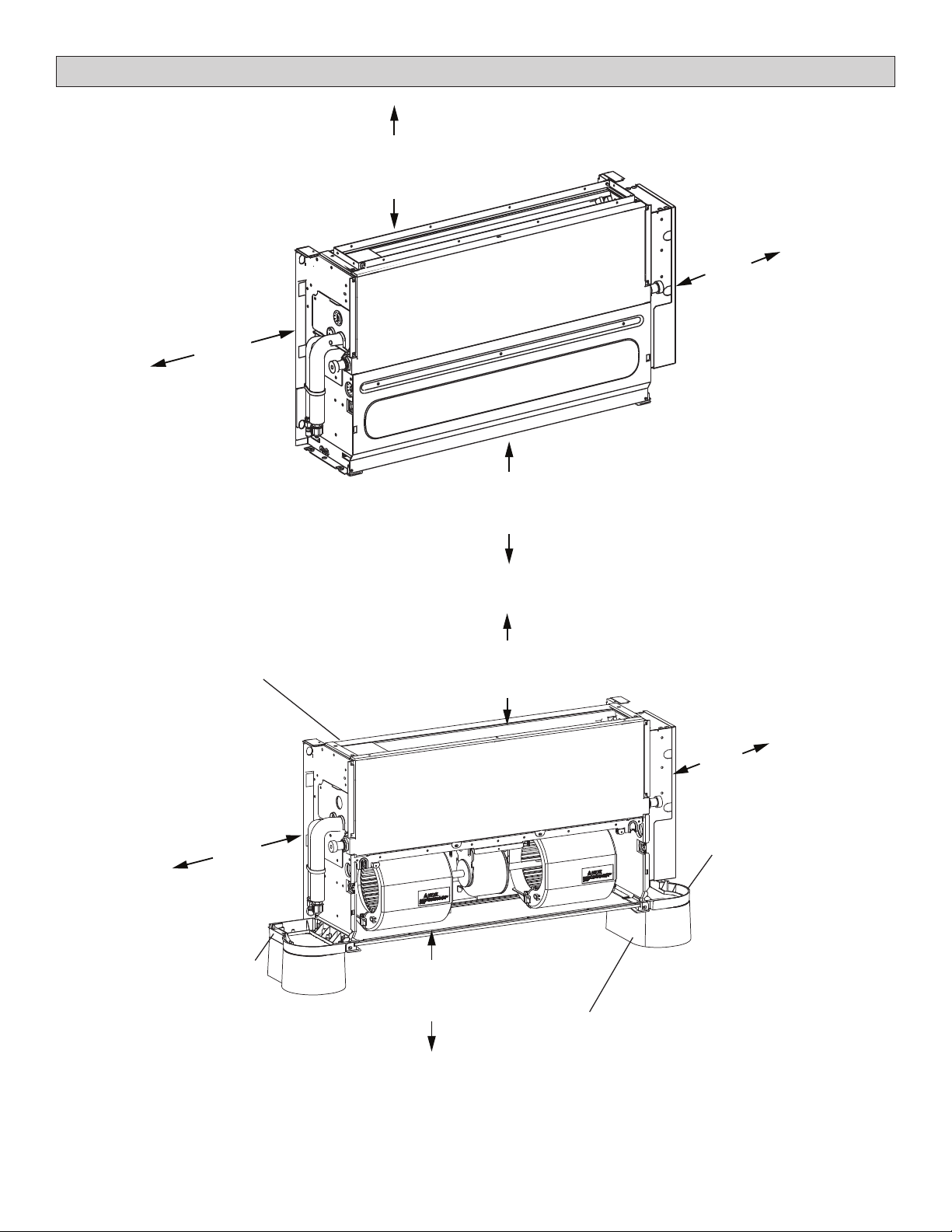
1. Remove the unit casing (VSC units only) by
removing the six screws shown in Figure 1.
After installation is complete, re-install the unit casing
by replacing the cover plate and side plate screws. It is
not necessary to replace the base screws.
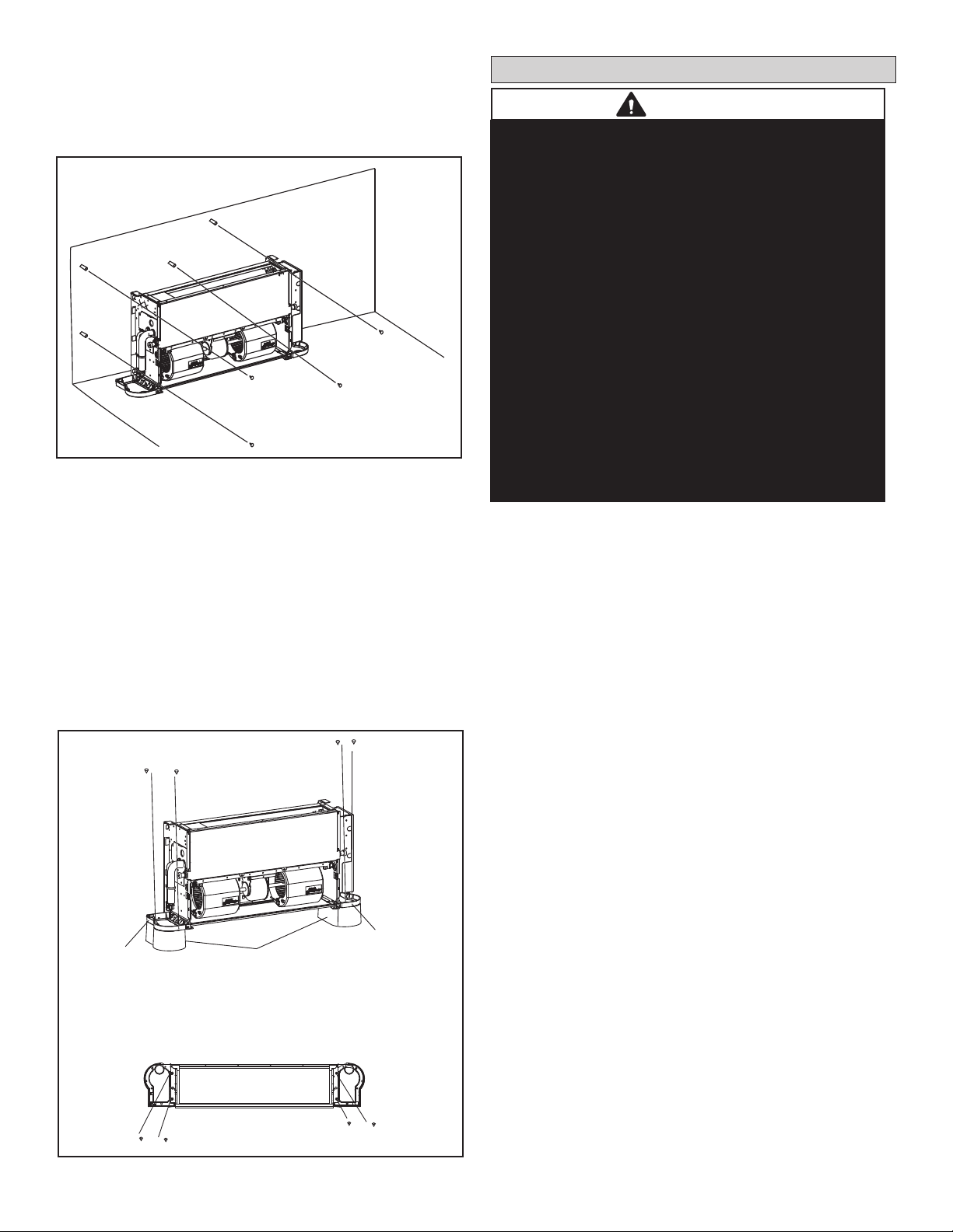
2. The unit can be secured to a wall or mounted
on optional support feet V8VSA001-3P (19X68).
Figure 1. Remove Casing Assembly (VSC Only)
Casing
Assembly
Base
Screws
Cover Plate
Screws
Side Plate
Screws

10
Secure to Wall (VSC or VSE Units)
Locate the unit on a wall which is both capable of supporting
the unit’s weight and which is constructed to enable the unit
to t ush on the wall. An uneven wall may lead to vibration
and subsequent unit damage.
Figure 3. Mount to Optional Feet
1. Mark the locations of the screws on the wall and use
suitable fasteners to secure the four mounting holes to
the wall. See Figure 2, and the dimension drawings on
Page 4 to ensure proper positioning of the unit.
2. The unit should be installed high enough for a gravity
drain to function properly. If necessary, a eld provided
external pump can be installed at the unit. See Page 4
for pipe connection locations.
Mount to Optional Feet
1. Place the mounting holes on the unit base into the
corresponding feet locating pin and install four screws
as shown in Figure 3.
Figure 2. Secure to Wall
Base
Base
BOTTOM OF UNIT
FRONT VIEW
Optional Feet Accessory
V8VSA001-3P (19X68)
Refrigerant Piping Connections
WARNING
Refrigerant leaks are unlikely; however, if a refrigerant
leak occurs, open a door or windows to dilute the
refrigerant in the room. Turn o the unit and all other
appliances that may cause a spark. Call a licensed
professional HVAC technician (or equivalent) to repair
the leak.
Use only R410A refrigerant to charge this system. Use
of other refrigerant or gas will damage the equipment.
Do not allow air or other contaminants to enter system
during installation of refrigerant piping. Contaminants
will result in lower system capacity and abnormally high
operating pressures and may result in system failure or
explosion.
Insulate all refrigerant piping.
Refrigerant pipes may be very hot during unit operation.
Do not allow contact between wiring and bare copper
pipes.
After refrigerant piping connections have been
completed,check thesystem forleaks per commissioning
instructions.
Field piping consists of two copper lines connected to the
indoor unit. Table 1 lists the connection sizes at the indoor
unit. The connections are made using the provided brass
are nuts at the end of the refrigerant piping connections.
Both lines must be individually insulated.
1. The seal on the unit refrigerant piping connections
should remain in place until the last possible moment.
This will prevent dust or water from getting into the
refrigerant piping before it is connected.
2. Slowly loosen one of the are nuts to release the
factory nitrogen charge.
3. Remove the are nuts from the connections on the
unit and discard the seal from each of the piping
connections.
4. Slide the are nuts onto the ends of the eld-provided
refrigerant piping before using a suitable aring tool
to are the end of the copper pipe.
5. Apply recommended HFC-410A refrigerant lubricant
to the outside of the ared refrigerant lines (Figure
4-A).
6. Align the threaded connections with the ared
refrigerant lines. Tighten the are nuts lightly at rst to
obtain a smooth match (Figure 4-B).
7. Once snug, continue another half-turn on each nut
which should create a leak-free joint. A torque wrench
may be used to tighten are nuts using Table 2
recommendations. See Figure 5. Do not over-tighten
a ared joint. Flared connections should always
be accessible and must be insulated to prevent
condensation.

11
IMPORTANT!
The compressor in this unit contains PVE
oil (Polyvinylether). PVE oil is formulated for
hydrouorocarbon (HFC) refrigerants, such as R-410a,
which this system contains. While it may have some
miscibility properties with mineral-based oil and POE oil
(Polyolester), it is not recommended to mix PVE oil with
any other type of refrigerant oil.
Nominal
Capacity
(Btuh)
Liquid Line
in.
Vapor Line
in.
7000
9000
12000
15000
18000
1/4 1/2
24000 3/8 5/8
Table 1. Refrigerant Piping Connections
A
B
APPLY REFRIGERANT LUBRICANT
ON THE OUTSIDE OF THE FLARE
MALE FLARE
CONNECTION
Figure 4. Making Connections
(Male to Female Connection)
8. After refrigerant piping has been installed and
checked for leaks, apply insulation over all ared joints
ensuring an air tight seal has been made between unit
connections and eld supplied insulated piping. All eld
piping connections shall be insulated and air tight to
prevent unwanted condensation build-up. Figure 6.
Flared connections should always be accessible
and must be insulated to prevent condensation. See
Figure 6.
Always use two wrenches when tightening are
nuts to avoid twisting refrigerant piping. DO NOT
over-tighten are nuts.
Outside
Diameter
Recommended
Torque
No torque wrench
available
Finger tighten and use
an appropriately sized
wrench to turn an
additional:
Inches U.S.
1/4” 15 ft.-lb. 1/4 turn
3/8” 26 ft.-lb. 1/2 turn
1/2” 41 ft.-lb. 7/8 turn
5/8” 48 ft.-lb. 1 full turn
Table 2. Flare Nut Torque Recommendations
IMPORTANT
UNIT
BASE
INSULATE ALL FLARED CONNECTIONS
TO PREVENT CONDENSATION
Figure 6. Insulate Flared Connections
IMPORTANT!
Figure 5. Tighten Flare Nut
To Indoor
Unit
Torque
Wrench
Backup
Wrench
To Outdoor Unit
IMPORTANT
Support ALL piping within 12 in. (305 mm) of any
mechanical tting such as a ared connection.

12
(Sloped at1/4” per foot AWAY from unit and should
be supported as needed to prevent sagging.)
MAIN DRAIN
(Sloped at1/4” per foot AWAY from unit and should
be supported as needed to prevent sagging.)
INDIVIDUAL DRAIN OUTLET
FROM EACH INDOOR UNIT
Condensate Piping Connections
CAUTION
!
Make sure that drain piping is properly routed
and insulated in order to prevent both leaks and
condensation.
1. Make a water-tight connection between the eld-
provided condensate drain line and the exible
condensate connector (1” O.D.).
2. Conrm proper slope (not less than 1/4 inch per foot)
and routing of condensate lines to ensure moisture is
drained away from the indoor unit.
3. Drain should be as short as possible and should not
have any droops or kinks that would restrict condensate
ow and shall be approved resistant pipe.
4. There must be a 2-inch space between the end of
the condensate drain and the nal termination point
(ground, open drain, etc.) to ensure that the line will
drain freely.
5. After the system installation is complete, the
condensate drain line must be checked for leaks and
proper drainage. If a eld-provided condensate pump
has been installed, it must be checked to ensure proper
operation. This check is part of the commissioning
sequence.
IMPORTANT!
Drain should have a slope of at least ¼ inch per foot
and should be approved corrosion-resistant pipe.
You must conrm operation of every drain and pump
in the system as part of the commissioning proce-
dure.
Figure 7. Single Indoor Unit Using a Properly Sloped
Gravity Drain
Figure 8. Multiple Indoor Units Using a Single Properly Sloped Gravity Drain
Indoor
Unit
Using an External Water Level Switch
Disconnect the closed circuit loop, CN 5. Connect the
water level switch cable accessory to CN 5. See unit wiring
diagrams for location of CN 5.
The connection has 5 VDC current, do not supply eld
voltage.
G
L2
L1
NC
COM
NO
PUMP
CONNECTIONS
0.5A
G
L1
L2
GREEN
OPTIMAL
Cut wire here
INDOOR
UNIT
MAIN
BOARD
Connect to
pump here
using solder
or butt joints
WATER
WATER
Figure 9. External Water Level Switch Connection
Indoor
Unit
Indoor
Unit

13
Wiring Connections
WARNING
!
Isolate the power supply before accessing unit
electrical terminals.
Install unit so that unit disconnect is accessible.
Follow all local and national codes, as well as this
installation instruction, during installation. Do NOT
overload electrical circuit, as this may lead to failure
and possible re.
Use specied wiring and cable to make electrical
connections. Clamp cables securely and make sure
that connections are tight to avoid strain on wiring.
Insecure wiring connections may result in equipment
failure and risk of re.
Wiring must be installed so that all cover plates can
be securely closed.
In the U.S.A., wiring must conform with current local codes
and the current National Electric Code (NEC). In Canada,
wiring must conform with current local codes and the current
Canadian Electrical Code (CEC). Refer to unit nameplate
for minimum circuit ampacity and maximum overcurrent
protection size.
NOTE - Three-conductor shielded cable must be used for
the communication wiring. This is necessary to ensure
proper system communication and operation.
CAUTION
!
This unit must be properly grounded and protected
by a circuit breaker. The ground wire for the unit must
not be connected to a gas or water pipe, a lightning
conductor or a telephone ground wire.
Do not connect power wires to the outdoor unit until
all other wiring and piping connections have been
completed.
Install all wiring at least 3 feet away from televisions,
radios or other electronic devices in order to avoid
the possibility of interference with the unit operation.
Do not install the unit near a lighting appliance that
includes a ballast. The ballast may aect remote
control operation. Tightening torque for the terminal screws
• Use the correct screwdriver for ghting the terminal
screws. If the screwdriver blade is too small, the head
of the screw might be damaged, and the screw will not
be properly tightened.
• If the terminal screws are over tightened, screws might
be damaged.
• Refer to the table below for the tightening torque of the
terminal screws.
A disconnection device having an air gap contact
separation in all active conductors should be
incorporated in the xed wiring according to the
National Wiring Regulation.
CAUTION
!
Table 3. Terminal Screw Tightening Torque
Tightening torque (lb-ft)
Terminal base of
remote controller/Signal
transmission wire (X2M)
0.58-0.72
Terminal base of power
supply (X1M)
0.87-1.06
Grounding terminal (M4) 1.06-1.43
• After wiring, conrm all connections are correct; Then
turn on power supply to the unit.
1. Pull the return air lter grille forward and remove the
lters.
2. Remove one screw from each safety strap assembly
(one on each side) and remove return air grille.
3. Locate the control box in the center of the unit, below
and behind the fan motor.
4. Remove the two screws holding the control box onto the
motor mounting bracket, and the screw at each end of
the control box holding securing the box to the chassis
of the unit. Lower the control box to obtain access to
cover.
5. Remove the screws securing the cover and remove
cover from control box.
6. Locate the terminal strip in the control box. Connect the
power wiring (sized per NEC/CEC and local codes)
and communications cable (three-conductor shielded
cable) per gures 12 and 13. Refer to unit nameplate
for rated voltage.
7. If the indoor unit is the nal unit in a group that is wired
in series, install the provided resistor across terminals P
and Q. See gure 14.
• A circuit breaker capable of shutting down the power
supply to the entire system must be installed.
• A single switch can be used to supply power to units on
the same system. However, branch switches and circuit
breakers must be selected carefully.
• Fit the power supply wiring of each unit with a switch
and fuse as shown in the wiring diagram.
• Install a wiring interrupter or ground-fault circuit
interrupter for the power wiring.
• Make sure the ground resistance is no greater than
100Ω. This value can be as high as 500Ω when using
a grounding fault circuit interrupter since the protective
ground resistance can be applied.

14
Indoor units and MS boxes on the same refrigeration
circuit should have a common power supply but must
have an independent disconnect switch installed adjacent
to the fan coil for servicing and maintenance purposes.
Indoor unit and MS box power supply MUST not be taken
from the outdoor unit. Always follow NEC/CEC and Local
Codes.
Figure 10. Typical Power Wiring Diagram (VRF Heat Recovery System Shown)
L2 L3L1
L2L1
208/230V 3Ph 60Hz
or 460V 3Ph 60Hz
Power supply
208/230V 1Ph 60Hz
Power supply
Mode Selection Box Indoor unit Indoor unit Indoor unit
Dedicated
breaker
Service
Disconnect
L1 L2
L1 L2
Fuse
Service
Disconnect
L1 L2
Fuse
Service
Disconnect
L1 L2
Fuse
Service
Disconnect
L1 L2
Fuse
Outdoor Unit (Main Unit)
L1 L2 L3
Outdoor Unit (Sub1 unit)
L1 L2 L3
Outdoor Unit(Sub2 Unit)
L1 L2 L3
L1 L2 L3
L1 L2 L3
L1 L2 L3
L1 L2 L3
L1 L2 L3
L1 L2 L3
Service
Disconnect
Service
Disconnect Service
Disconnect
IMPORTANT
DO NOT adjust DIP switch settings. Settings may only be
adjusted by a trained technician as part of the commis-
sioning procedures.

15
Figure 11. Typical Communication Wiring Diagram (VRF Heat Recovery System)
NOTE - Each communication wire from the MS box should follow the refrigerant piping for that port.
P Q
All Drain Wires will connect from outdoor unit chassis to mode selection box chassis at the end of
the signal run.
18 GA., stranded, 2-conductor, shielded control wire (polarity sensitive).
Typical Wiring Diagram, NEC/CEC and Local Codes apply.
Outdoor unit Outdoor unit
(sub1 unit)
Outdoor unit
(sub2 unit)
(PQ)
(main unit)
(PQ)
MS
Box
(PQ)
(PQ)
MS
Box
(PQ)
(PQ)
(H1 H2 ) (H1 H2 ) (H1 H2 )
Outdoor Unit Communication Terminal Block
P Q H1 H2X YO AK1 K2
MS Box Communication
Terminal Block
P Q
Indoor Unit Communication Terminal Block
HA HB 12V COM P Q
Ground drain wire or
cable shield
to MS Box
and Outdoor Unit chassis
Install a terminating resistor (Ω120) on terminals P&Q on the indoor unit
which is furthest from the outdoor unit.

16
Figure 12. Typical Communication Wiring Diagram (VRF Heat Pump System)
(PQ)
(PQ)
Outdoor unit
(mainunit)
Outdoor unit
(sub1unit)
Outdoor unit
(sub2 unit)
Install a terminating resistor (Ω120) at the last indoor unit terminals P and Q of the daisy chain.
P Q
All shields of shielded cable connect to chassis GROUND terminal at Indoor Units.
18 GA., stranded, 2-conductor,shielded control wire (polaritysensitive).
Typical Wiring Diagram, NEC/CEC and Local Codes apply.
(H1 H2 )
Outdoor Unit Communication Terminal Block
P Q H1 H2X YO AK1 K2
(H1 H2 )
(H1 H2 )
Indoor Unit Communication Terminal Block
HA HB 12V COM P Q
Ground cable shield
to Indoor Unit chassis

17
Figure 13. VSCA & VSEA Wiring Diagram
EEV
FM
ALARM
PUMP
CN18CN3
CN24
CN2
EARTH
Y/G
CN15CN9
CN17
Y/G
L1 L2
CN51
CN50
HHE interface
( Current range:
0-1A)
(Voltage range:
0-24V AC/DC)
FAN
CTON
HTON
AUXH
T2A
T2B
T2
T1
XS5
XP5
Display Board
RED BLUE
N=5
YELLOW
GRAY
WHITE
BLUE
ON/OFF
SWITCH
Occupancy
sensor
Main Board
CS
POWER IN
XT1
XT2
CN21
CN26CN4
CN5
CN54 CN52 CN8
T2A
T2B
T2
EEV
Warning lamp
Electronic expansion valve
ALARM
Indoor fan motor
Room temperature sensor
T1
FM
Code Title
XS1-7
XP1-7
XT1-2
Connectors
Terminals
Pump motor
Water level switch
Swing motors
PUMP
GM1-2
CS
Error CodeError Content
E1
E0
E2
E3
E4
Mode conflict
Communication error between
indoor and main outdoor unit
E5
FE
D8
A0
Eb
U4
Ed
EE
F8
No address
Outdoor unit fault
Water level alarm
Emergency stop
Remote off
E6
DC fan motor error
E7
EEPROM failure error
“ +5V GND +12V ”
ONLY USED
FOR TESTING
CN30
RED
BLACK
HA HB 12V COM QP
To wired
controller
comm. bus
To outdoor/
indoor/MS
units
comm.bus
To wired
controller
power
MS error
CN14
GM1 GM2
XP6
XP4
XP3
XP2
XP1
BLUE
BLACK
WHITE
RED
XS4
XS3
XS2
XS1
XS6
XP7 XS7
CN12
NOTE:
1. Refer to manual for communication
wiring
2. Please use the 2-conductor shielded
twisted cable for communication
NOTE:
Component in dash line is
optional or field wiring
Inlet of evaporator sensor
Outlet of evaporator sensor
Middle of evaporator sensor
T1 (Room temperature sensor) malfunction
T2 (Middle of evaporator sensor) malfunction
T2A (Inlet of evaporator sensor) malfunction
T2B (Outlet of evaporator sensor) malfunction
MS self-inspection error
EEV malfunction
CN1
Connect Receiver/Display
The unit’s Receiver/Display is eld installed and connected
as shown in Figure 14.
1. Align the plastic tabs on the back of the receiver to the
slots on the top of the unit’s electrical control box and
slide the tabs into the slots.
Figure 14. Install Receiver/Display
2. Connect the 10-wire harness connection to the unit’s
main control board CN 05.
3. Connect the 5-wire harness connection to the optional
wired controller V0STAT55P-3 (19X69) if used.
See Page 14 for spot check and troubleshooting
instructions using the Receiver/Display panel.
Connect to
Indoor Unit
Main Board
Connect to
Optional
V0STAT55P-3
Controller

18
Optional Wired Controller V0STAT55P-3 (19X69)
Input voltage 12 VDC
Ambient temperature 23~110°F (-5~43°C)
Ambient humidity RH40%~RH90%
Table 4. V0STAT55P-3 Specications
Cool Heat Dry Auto
Setpoint
Fan
Auto
Speed Fan
Speed
Fan
Speed
Button
Temp
Setting
Buttons
Mode
Button
Backlight
Button
Power
Button
Figure 16. V0STAT55P-3 Display & Buttons
Display
Area
Frequent changes to operating mode may cause
system malfunction. Allow at least one minute between
mode changes to allow the system to stabilize.
IMPORTANT
!
Electrostatic discharge can aect electronic
components. Take precautions to neutralize
electrostatic charge by touching your hand and tools
to metal prior to handling the control.
IMPORTANT
!
V0STAT55P-3 is an optional wired non-programmable lo-
cal controller that controls VSC/VSE Floor Standing indoor
units. These instructions are intended as a general guide
and do not supersede local codes in any way. Consult au-
thorities having jurisdiction before installation.
• Be sure that the indoor unit power supply has been turned
o before beginning installation.
• This controller should be used only as described in this
manual.
• Do not install the controller on outside walls (where there
is unconditioned space on opposite side of wall) or in lo-
cations where direct sunlight may be present.
General
Shipping & Packing List
1 - Wired Controller
4 - Mounting screws
4 - Plastic anchors
1 - Connection Wiring Harness - 49 ft. (15 m)
Figure 15. V0STAT55P-3 Controller Assembly
Requirements

19
4
(102)
3
(76) 5/8
(16)
2-3/8
(60)
1-5/8
(41)
1-1/8
(29)
Figure 17. V0STAT55P-3 Dimensions
Figure 18. V0STAT55P-3 Schematic and Connection Diagram
IDU Electrical
Control Box
IDU Main
Control Board
Back of
Controller
10-Conductor
Wiring Harness
Display / Receiver
Panel
5-Conductor
Wiring Harness
To Indoor Unit
Main Board
Connect
to
Receiver
Connect
to
Controller
Wiring
Harness
Plug into
back of
the
Controller
Indoor Unit
Electrical
Control Box
VSC/VSE Indoor Unit
Receiver/Display
Receiver/Display
Wiring Harness
Controller
Wiring Harness
49 ft. (15 m)
Controller

20
The V0STAT55P-3 controller can be mounted inside of
the VSC/VSE unit or on a wall.
After powering on the controller, wait 30 seconds for initial-
ization The indoor unit cannot be controlled by the controller
until initialization is complete.
Start/Stop Operation
Press the Power button.
• Controller ON: LED display lit.
• Controller OFF: LED display not lit.
Set Operation Mode
Press the Mode button to scroll through the mode selec-
tions.
• Cool – System operates in cooling mode.
• Heat – System operates in heating mode.
• Dry -- System operates in dehumidication mode. NOTE -
fan speed cannot be adjusted during dry mode.
• Auto -- System operates in auto mode.
• Fan – Fan only, no heating or cooling.
To set (or change) the room temperature setting (set-
point)
Press the up-arrow & down-arrow buttons to adjust the set-
point.
When in Auto mode, separate heating and cooling setpoints
can be set. Press the Mode button to switch between heat-
ing and cooling setpoints.
Backlight
• The backlight turns on when the controller is powered
on. The backlight automatically turns o after 4 sec-
onds.
• Press the Backlight button to turn on the backlight.
Press any button except for Backlight and Power to turn
o the backlight.
Temperature Unit Display
• Press the Mode button and the Down arrow button and
hold for 3 seconds to toggle between Fahrenheit and
Celsius temperature display.
NOTE - Indoor units connected to a local controller may
also be controlled by a centralized controller. Indoor units
respond to the last command sent. It is recommended that
indoor units be controlled from a single source of control,
either local controller or centralized controller but not both,
to avoid conicts in commands.
OperationController Installation
This manual suits for next models
13
Table of contents
Other Lennox Heating System manuals

Lennox
Lennox AXIL Series User manual

Lennox
Lennox VRB Series Installation instructions

Lennox
Lennox CompleteHeat AM30 Instruction Manual

Lennox
Lennox 13CHA SERIES User manual

Lennox
Lennox Harmony III User manual

Lennox
Lennox Lennox CompleteHeatTM COMBINATION HEATING... Guide

Lennox
Lennox CompleteHeat Guide
Popular Heating System manuals by other brands

2VV
2VV SAVANA INOX Plus Installation and operation

Vehicle Systems
Vehicle Systems Aqua-Hot AHE-100-04S Shop Manual

System air
System air SAVE VTC 700 with reheater installation instructions

Magic-Pak
Magic-Pak MGE4-09-18 Installation and maintenance instructions

ProFusion
ProFusion PH-945 user manual

Ambirad
Ambirad Herringbone HB manual