Regulus ETT-D2 User manual
www.regulus.eu
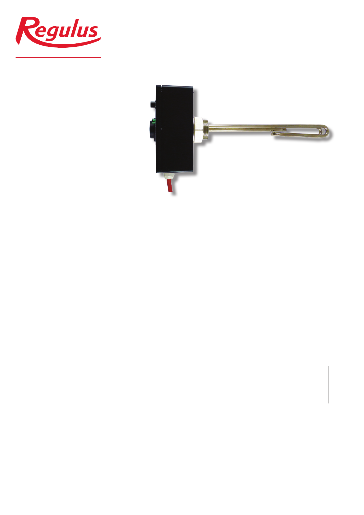
ETT-D2 Electric Heating Element
ETT-D2 Electric Heating Element
EN
Installation and Operation Manual
Heating Element with Thermostatic Head,
single-phase, fixed wiring
│2
REGULUS - Electric Heating Element - www.regulus.eu
1 - General
1.1 - Application
This electric heating element is designed to heat domestic hot water in a hot water storage tank or heating
uid in a heating system thermal store.
1.2 - Installation
Screw the el. heating element into the respective threaded connection (G 6/4” F) so that the cable gland points
downwards. Sealing cord, hemp, Teon tape or semi-permanent thread sealant should be used to avoid leaks.
1.3 - Maintenance
Clean the exterior of the heating element with a soft cloth and a suitable detergent. Never use abrasive clean-
ers or solvents.
If the element is used in hard water, it is recommended to remove sediments at least once a year. Unplug the
element before cleaning. Then drain water from the tank and dismount the heating element. Scratch the hard
deposits on the heating rod with a plastic or wooden spatula and ush with water. Be careful not to damage
the protective nickel layer on the heating rod. Then reinstall the element according to this instruction manual,
ll the tank with water, air-bleed and pressurize it. Check the threaded connection for leaks. Finally, reconnect
the heating element to the mains.
1.4 - Disposal
IMPORTANT INFORMATION ON DISPOSAL IN COMPLIANCE WITH THE EUROPEAN
DIRECTIVE 2002/96/EC
Do not dispose of this product as unsorted municipal
waste. Please dispose of this product by returning it to
the point of sale or to your local municipal collection
point for recycling.
Respecting these rules will help to preserve, protect
and improve the quality of the environment, protect
human health and utilize natural resources prudently and
rationally.
The crossed out wheeled bin with marking bar, printed
ether in the Manual or on the product itself, identies that
the product must be disposed of at a recycling collection
site.
WEEE registration number: 02771/07-ECZ
3 │
REGULUS - Electric Heating Element - www.regulus.eu
2 - Nickel-plated heating element with thermo-
static head, single-phase, xed connection
2.1 - Technical description
The electric heating element consists of a nickel-plated heating element with G 6/4“ male thread, a capillary
thermostat adjustable between 0±5 °C and 90±3 °C (the lower limit is factory set to 15 °C as a frost protection
and the upper limit is set to 60 °C for use in hot water storage tanks) with 5±1 °C switching difference, a two-pole
capillary safety thermostat with manual reset set to 99 °C and +0 °C, -10 °C tolerance, a 5×1.5 mm² power cable,
LED lights to indicate the status of the heating element. The power cable is 2 m long.
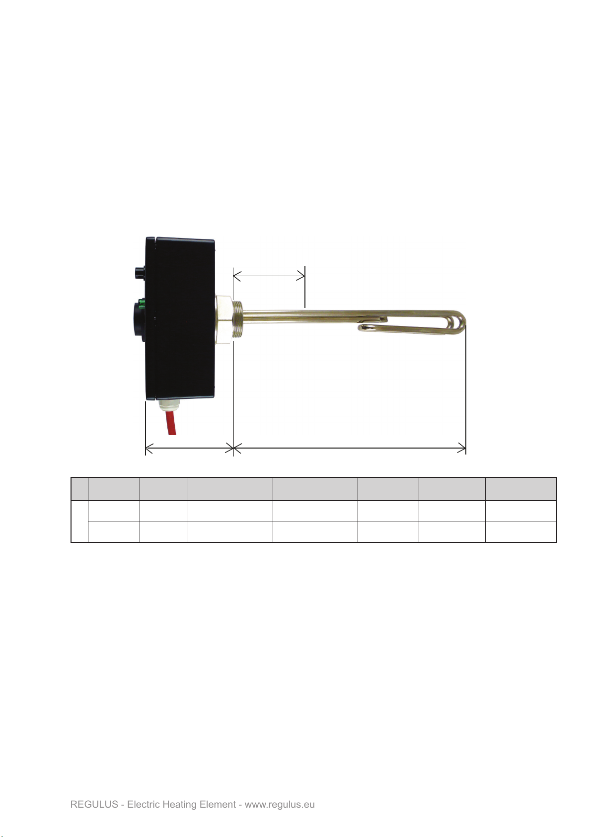
2.2 - Dimensions
model output [kW] el. connection material LN-non-hea-
ting end [mm]
L-heating rod
length [mm]
code
230 V
ETT-D2-2.0 2 1/N/PE AC 230V nickel-plated copper 100 315 19703
ETT-D2-3.0 3 1/N/PE AC 230V nickel-plated copper 100 370 19710
2.3 - Connection to power supply
The electric heating element connects to the terminal box or to the 1/N/PE AC 230V mains switchboard by
a xed connection. The installation shall be carried out in accordance with valid regulations and standards by
a specialized company or trained staff.
The wire marked N-HDO is designed for controlling the heating element by Ripple control. If this connection is
not used, the two blue center wires (N and N-HDO (Ripple c.)) must be joined together in the terminal box or
in the mains switchboard.
The wire marked OVLÁDÁNÍ (CONTROL) (L) is intended to control the heating element via the heating sys-
tem controller. This wire is connected to the phase switched by the controller. In this case, the thermostat knob
must be set to a higher temperature than that set in the controller. If this connection is not used, this wire must
be joined together with the live wire L in the terminal box or in the mains switchboard.
100 L
LN

│4
REGULUS - Electric Heating Element - www.regulus.eu
2.4 - Wiring diagram
2.4.1 - Wiring diagram of the heating element
2.5 - Commissioning, operation and possible faults
WARNING!
THE HOT WATER OUTLET MUST NOT BE MADE IN COMMON PLASTIC PIPING. THE
PIPING USED SHALL BE RESISTANT TO TEMPERATURES OF 100 °C AT LEAST.
IF PLAIN COMMON PLASTIC PIPING IS USED, ITS SERVICE LIFE IS SIGNIFICANTLY
REDUCED UNDER TEMPERATURES OVER 60 °C. WHEN COMBINED WITH IMPROP-
ER PIPE FIXING THAT PREVENTS/RESTRICTS ITS DILATATION, THE PIPE SERVICE
LIFE MIGHT BE JUST SEVERAL HOURS!
Prior to commissioning, please make sure TDS of water in direct contact with the heating element does not ex-
ceed the values shown in the chart below. The manufacturer bears no responsibility for defects (e.g. limescale
deposits on the heating element) caused by unsuitable operating conditions.
Table of limit values for total dissolved solids in hot water
Description pH Total dissolved solids (TDS) Ca Chlorides Mg Na Fe
Max. value 6,5-9,5 600 mg/l 40 mg/l 100 mg/l 20 mg/l 200 mg/l 0,2 mg/l
GREEN GREEN
CONTROL (L)
Ripple c. (N)
No. 1
No. 2
No. 3
No. 4
5 │
REGULUS - Electric Heating Element - www.regulus.eu
2.5.1 - DHW heating in a hot water storage tank
In order to heat water in the hot water storage tank, open the cold water inlet valve, ll the tank with water and
airbleed it by opening the hot water tap. Set the thermostat knob to the desired temperature. The two green
lights on the heating element will light up. When the water is heated to the desired temperature, the green light
marked will go out. The green lights will be on to indicate that the heater is connected to the mains and
is switched on. If the green light marked is not lit, the heating element is switched off by the adjustable
thermostat.
It is recommended to set the thermostat knob to 60 °C. This temperature guarantees the best operation of the
heating element and at the same time, it offers:
- protection against Legionella
- cost reduction
- slower deposit formation
2.5.2 - Heating uid heating in a heating system thermal store
Fill the heating system with heat-transfer uid, air-bleed it and pressurize to the working pressure. Set the ther-
mostat knob to the desired temperature.
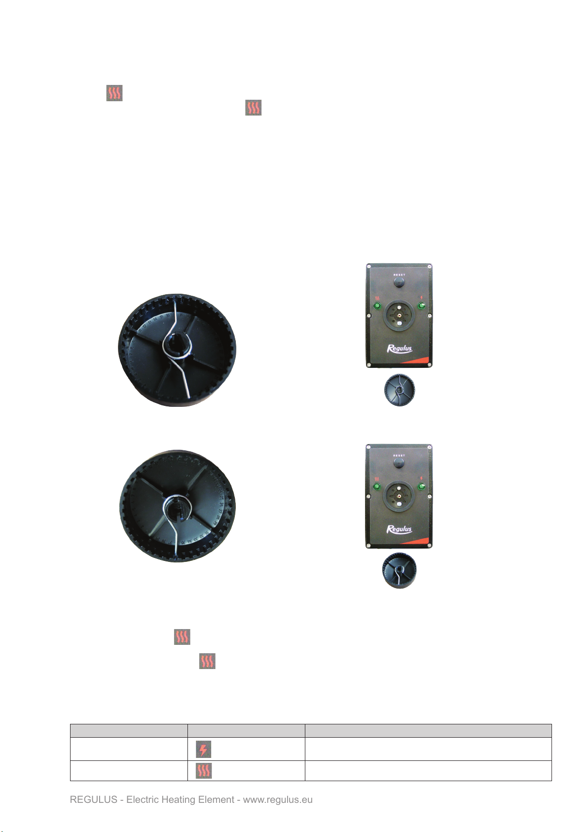
If a temperature above 60 °C is to be set, the limiting spring under the knob shall be removed.
Steps:
- Pull the knob off the shaft.
- There are two limiting springs inside the knob. Remove the upper spring. It is tted in the groove 17
and limits the adjustable temperature to 60 °C. (Just one spring will remain in the knob, tted in the
groove 37, it limits the min. adjustable temperature to 15 °C.)
- Re-t the knob on the thermostat shaft
This modication will increase the thermostat adjustment range to 15-90 °C.
Colour Indication Description
Green The heating element is in order, connected to the mains and ready
for use
Green Heating element is heating
The two green lights on the heating element will be on. When the water is heated to the desired temperature,
the green light marked will go out. The lit green indicator LEDs indicate that the heating element is con-
nected to the mains and switched on.
If the green LED light marked is not lit, the heating element is switched off by the adjustable thermostat.
2.5.3 - Heating element state during operation
During operation, the status of the heating element is indicated by indicator lights with the following meaning:

│6
REGULUS - Electric Heating Element - www.regulus.eu
3 - Examples of heating element connection
When the safety temperature limit is reached, the safety thermostat will cut off the power supply. In this state,
no indicator light is lit. The safety thermostat features no automatic reset. After the tank has cooled down, the
heating element shall be switched on again by pressing the button after unscrewing the cap on the heating
element cover. The green LED indicator marked will light up and the heating element is ready for oper-
ation again. Repeated occurrence of this condition indicates a failure of the heating element. In this case,
disconnect the heating element from the power supply and call a service technician.
2.5.4 - Possible faults of the heating element
If the heating element is controlled by a heating system controller and after the controller switches on, the oth-
er green LED light does not light up when the green LED light marked is lit, the adjustable thermostat
knob is probably set to a lower desired temperature than at the controller. Set the thermostat knob to
a higher desired temperature. If even then the other green light does not light up, call a service technician.
If the tank overheats without using another heat source (the adjustable thermostat probably does not turn off
the heating element when the set temperature is reached - the green LED light marked remains on until
both lights go out), call a service technician.
If the heating element shows signs of another malfunction, immediately disconnect the heating element from
power supply and call a service technician.
Controlled by a master controller or a thermostat
LN
Externí regulace
PE
LN-HDO
NL-OVL PE
El. top. těleso - zásobník TV
bez HDO
L1
L2
L3
N-HDO
PE
N
výstup ohřev TV - 230V
kódy Regulus - 11783, 11784, 11785, 11786
Ovládání přes ext. regulaci bez HDO
Controlled via an external controller without Ripple control
External controller
without Ripple control
El. heating element - hot water tank
Regulus codes - 19703, 19710
DHW heating output - 230V

7 │
REGULUS - Electric Heating Element - www.regulus.eu
N-HDO
NL-OVL PE
El. top. těleso - zásobník TV
L1
L2
L3
N-HDO
PE
N
kódy Regulus - 11783, 11784, 11785, 11786
Ovládání přes integrovaný termostat
LN
Externí regulace
PE
LN-HDO
NL-OVL PE
El. top. těleso - zásobník TV
s HDO
L1
L2
L3
N-HDO
PE
N
N-HDO
výstup ohřev TV - 230V
kódy Regulus - 11783, 11784, 11785, 11786
Ovládání přes ext. regulaci s HDO
External controller
without Ripple control
El. heating element - hot water tank
Regulus codes - 19703, 19710
El. heating element - hot water tank
Regulus codes - 19703, 19710
DHW heating output - 230V
Controlled via an external controller with Ripple control
Controlled via the integrated thermostat

Heating Element with Thermostatic Head,
single-phase, fixed wiring
WARRANTY CERTIFICATE
Model: .......................................................................................
Serial number: .......................................................................
Seller: .......................................................... Date of purchase: ...............................
1. The warranty period is 24 months from the date of purchase
2. The product shall be installed and commissioned by a competent company or a person
trained by the Manufacturer.
3. When claiming warranty, this Warranty Certicate must be submitted together with the
purchase receipt.
4. The warranty is valid only when the technical conditions set by the Manufacturer,
installation manual and instructions in the documentation and on the product itself are
respected.
5. The warranty does not cover defects caused by external conditions or improper working
conditions, defects caused by normal wear and tear, further when the product is not used
in compliance with its purpose and when the defect was caused by mechanical damage
to the product, improper handling, tampering by a third person, improper installation,
improper stocking, natural disaster etc.
COMMISSIONING
Company: …………………....................……………..
Date: ……………….................................……..
Rubber stamp print and signature of the technician:
WARRANTY CONDITIONS
©2022 We reserve the right to errors, changes and improvements without prior notice.
REGULUS spol. s r.o.
E-mail: [email protected]
Web: www.regulus.eu
v1.0-09/2022
This manual suits for next models
2
Table of contents
Other Regulus Heating System manuals


