Sukup Spredway Quick start guide

Spredway®
Owner’s
Installation and Operation Manual
Sukup Manufacturing Co.
1555 255th Street, Box 677
Sheffield, Iowa, USA 50475-0677
Phone: 641-892-4222
Fax: 641-892-4629
Manual L1431 ©Sukup Manufacturing Co.
12/05/2017
D
ATES
R
EVISIONS
P
AGES
12/05/2017 – Updated operation instructions .......................................................................................................10

Table of Contents
2
TABLE OF CONTENTS
Proper management is essential to ensure satisfactory performance. Sukup Manufacturing Co. is not
liable for damage to grain resulting from improper management during drying or storage.
Limited Warranty...........................................................................................................................3
Safety Section ..............................................................................................................................4
Assembly......................................................................................................................................7
Installation ....................................................................................................................................8
Operation......................................................................................................................................10
Troubleshooting Guide..................................................................................................................10
Specifications ...............................................................................................................................11
Wiring...........................................................................................................................................11
Optional Pre-Spread Funnel .........................................................................................................11
Parts Identification........................................................................................................................12
Standard and High Capacity Spredway – Galvanized (G01051).................................................12
Super High Capacity Spredway – Galvanized (G0250)...............................................................14
Contact Information ......................................................................................................................16

Limited Warranty
3

Safety Section
4
On safety decals, this symbol and the
signal words Danger, Warning, Caution
and Notice draw your attention to
important instructions regarding safety.
They indicate potential hazards and levels of intensity.
RED - DANGER indicates an
imminently hazardous
situation which, if not avoided, will result in death or
serious injury.
ORANGE - WARNING
indicates a potentially
hazardous situation which, if not avoided, could result
in death or serious injury.
YELLOW - CAUTION
indicates a potentially
hazardous situation which, if not avoided, may result
in minor or moderate injury.
BLUE - NOTICE alerts you to
practices unrelated to personal
injury, such as messages related to property damage.
IMPORTANT: To prevent serious injury or death to
you or your family, it is essential that safety decals
are clearly visible, in good condition, and applied to
the appropriate equipment.
FOLLOW MANUAL & SAFETY DECAL MESSAGES
Carefully read this manual and
all safety decals on your
equipment. Safety decals must
be kept in good condition.
Replace missing or damaged
safety decals by contacting Sukup
Manufacturing Co. via mail at PO
Box 677, Sheffield, Iowa USA, 50475; by phone at
It is the responsibility of the owner/operator to know
what specific requirements, precautions, and work
hazards exist. It is also the responsibility of the
owner/operator to inform anyone operating or
working in the area of this equipment of hazards and
safety precautions that need to be taken to avoid
personal injury or death. Always keep children away
from bins and vehicles with flowing grain.
Make no unauthorized modifications to machine.
Modifications may endanger function and/or safety of
unit. Keep unit in good working condition. Keep shields
in place. Replace worn or missing shields free of
charge by contacting Sukup Manufacturing Co.
GRAIN BIN SAFETY
Owners/operators are responsible for developing
site-specific confined space entry procedures.
OSHA’s confined space entry procedures (29CFR
1910.146) can be found at www.osha.gov.
If you must enter bin for repair or maintenance:
•Use a safety harness, safety line and respirator
•Station another person outside of bin
•Avoid the center of the bin
•Wear appropriate personal protective equipment
•Keep clear of all augers and moving parts
DANGER: Never enter bin unless all power is
locked out and another person is present.
Rotating augers
can kill or
dismember!
NEVER enter bin when augers are running!
When bin is nearly empty, sweep auger will travelat an
increasinglyfast speed. Keep awayfrom sweepand
sump augers to avoid entanglement.
Failure to follow precautions above will result in death
or serious injury.
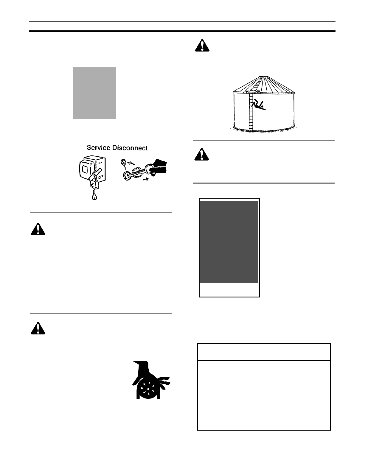
DANGER: Flowing grain
may trap and suffocate. If
you enter a bin of flowing grain
you can be completely submerged
in grain in about 8 seconds.
Failure to heed this warning will result in death or
serious injury.
Read manual before installing or using product. Failure to follow instructions and safety precautions in
manual can result in death or serious injury. Keep manual in a safe location for future reference.

Safety Section
5
Refer to OSHA 1910.132
(Personal Prot. Equip.)
To avoid electric shock or electrocution, all
equipment must be properly wired and grounded
according to electrical codes. Have unit wired by
qualified electrician.
Have an electrician install a main power disconnect
switch capable of being locked only in OFF position.
Mark disconnect
clearly as to
equipment it
operates.
Always lock out
main power
disconnect
switch whenever
equipment is not
in use.
WARNING: When servicing equipment, never
enter bin unless all power is locked out and
another person is present. Always LOCK OUT
all power and always check with voltage meter before
servicing.
Failure to do so could result in death or serious injury.
Owners/operators are responsible for developing
site-specific Lockout/Tagout procedures based on
equipment at their work site. See OSHA’s typical
minimal lockout procedures (29CFR 1910.147 App A)
at www.osha.gov.
WARNING: KEEP CLEAR OF ALL MOVING
PARTS.
Keep people (ESPECIALLY YOUTH) away from
equipment, particularly during operation.
Keep away from all moving parts.
Keep all shields in place. SHUT
OFF AND LOCK OUT all power
before servicing.
Failure to follow precautions above
could result in death or serious
injury.
WARNING: Metal is slippery when wet. To
avoid falls, never carry items if climbing on
bin. Maintain secure hand and foothold if climbing on
bin. Failure to do so could result in death or serious
injury.
CAUTION: Metal edges are sharp. To avoid
injury, wear protective clothing and handle
equipment and parts with care.
Failure to dosomayresult in minor or moderate injury.
PERSONAL PROTECTIVE EQUIPMENT
Owners/Operators are
responsible for developing
site-specific personal
protective equipment
standards. OSHA’s
personal protective
equipment standards
(29CFR 1910.132) can be
found at www.osha.gov.
EMERGENCIES – KNOW WHAT TO DO
Have emergency numbers and written directions to
work site readily available in case of emergency. An
area for emergency phone numbers to be recorded is
provided below and at end of this manual.
Ambulance • Fire • Police: 9-1-1
Bin rescue team: _______________________
Emergency medical squad: ______________
Address of work site: ___________________
Directions to work site:__________________

Safety Section
6
Safety decals should be mounted on your equipment
as shown in this safety section. Yearly and prior to
equipment use, check that all decals and shields are
in place and legible.
To order a replacement decal or shield at no charge,
contact your dealer or Sukup Manufacturing Co.,
Box 677, Sheffield, IA USA 50475. If replacement is
necessary, make sure location for decal is free from
grease, oil and dirt. Remove backing from decal and
place in proper position.
Decals 1 and 2 must be mounted during installation.
Decal 3 is mounted at factory. Make sure location for
decal is free from grease, oil, and dirt. Remove
backing from decal and place in proper position.
IMPORTANT: If suggested locations are not clearly
visible, place safety decals in a more suitable area.
Never cover up any existing safety decals.
1. DECAL L0281 – WARNING: To avoid serious
injury or death. Mount this decal on bin sheet
near door handle.
2. DECAL L0258A – DANGER: Do not enter this
bin! Mount this decal on bin sheet near door handle
and at all other entry points. Also mount this decal at
eye level on bin sheet near ladder going to roof.
3. DECAL L0284 – WARNING: Keep away from all
moving parts. Decal is factory-mounted on motor.

Assembly
7
Fig. 1 – Placement of belt on pulleys
Fig. 2 – Mounting pans to spreader
ASSEMBLY
Read all instructions carefully before beginning. Spredway model number is printed on Spredway
shipping carton. Standard Spredways are marked "Spredway." High Capacity Spredways are marked
“High Capacity.” Assemble Spredway according to drawings on this page and following instructions.
1. Bolt motor to motor mount using four 5/16 x 1" bolts, nuts and lock washers. Align motor pulley to flat
pulley by sliding on motor shaft. NOTE: Align belt when Spredway is in operating position.
2. Place belt on pulleys. Bend belt hook around belt as shown.
CAUTION: Belt should not scrape on hook or it may cut belt.
3. Center flow holes in spreading pans should be about 1/3
open for bins less than 24' in diameter. For larger bins,
holes should be 1/2 open. Be sure bolt on cover is tight
after adjustment.
4. To mount pan to spreader, lower pitch adjusting rod by
loosening locking handle and pre-spread disc inside of cone.
Lower adjusting rod so its end is about 3" below main bearing
shaft. See Fig. 2. One end of stationary pitch control arm
comes mounted to pan. Mount other end of control arm to
main bearing shaft. Secure with hairpin clips. Repeat this step
for second pan.
5. Remove hinge pin from
adjusting rod. Place
spreading pans and pitch
adjusting rod together and
replace hinge pin. Secure
hinge pin with hairpin clip.
Hairpin clips should be
snapped on all the way. See
Fig. 2. See operating
instructions for setting angle
of pans.
6. Place pre-spread ring inside
cone, allowing slots in ring to
slip over Spredway arms.
Secure ring by installing
hairpin clips - found in parts
sack - through holes
provided in Spredway arms.
7. After Spredway has been
assembled it is ready to be
installed in bin. Following
figures show different ways
to mount Spredway.
Determine which applies and
follow instructions for that
method. Spredway is
shipped with a set of
standard rigid mount
brackets.

Installation
8
Fig. 4 – Super High-Capacity
INSTALLATION
Hanger Brackets
Standard and Hi-Capacity with Rigid Mount
1. Divide circumferences of
center fill ring into three (3)
equal parts. Position
brackets so Spredway will
be level. If holes are
provided in peak ring,
Steps 1 and 2 may be
eliminated.
2. Mark and drill 5/16” holes.
Bolt brackets into place.
3. Holes have been provided
in rigid mount hanger
brackets to allow for
multiple Spredway
positions. Bolt Spredway
to brackets using 5/16 x 1"
bolts. Ensure Spredway is
level.
REF
#
DESCRIPTION
QTY
.
COMP
.
#
1 Rigid hanger, 2006 (3) 1 set G0197A
2 Peak ring bracket (Rigid) (3)
1 set G0196A
3 Bolt, 5/16 - 18 x 1”, PLT 18 J0527
4 Lock washer, 5/16", PLT 18 J1200
5 Hex nut, 5/16” - 18 18 J1002
6 Flat washer, 5/16" 18 J1111
Super Hi-Capacity
1. Divide circumferences of center fill ring into three (3)
equal parts. Position brackets so Spredway will be
level.
2. Mark and drill 5/16" holes. Bolt brackets into place.
3. Place hangers into slots on Spredway cone straps
and lower Spredway into opening*. Place hangers
into slots on brackets bolted to fill ring. Ensure
Spredway is level.
REF. #
DESCRIPTION QTY.
COMP. #
1 Hanger, 15" (3) 1 set G0212A
Hanger, 26" (3) 1 set G0213A
2 Adapter hanger bracket (3)
1 set G0125A
3 Bolt, 5/16 - 18 x 1”, PLT 6 J0527
4 Lock washer, 5/16" 6 J1200
5 Nut, 5/16" - 18 6 J1002
*If bin’s fill ring is too small for Spredway to fit through, use a winch to raise it from inside of bin.
Fig. 3
–
Standard and
Hi-Capacity w/ rigid
mount

Installation
9
Fig. 6 – MFS bracket
Sioux
1. Bolt Sioux brackets to Spredway cone straps with
5/16" bolts.
2. Lower Spredway into fill ring*. Ensure Spredway is
level. Mark and drill 5/16" holes. Bolt Spredway into
place.
3. Use optional vertical brackets if required. If pre-
spread funnel is used, use longer vertical brackets.
See Fig. 5.
MFS
1. Bolt brackets to Spredway cone straps with 5/16" bolts.
2. Lower assembled Spredway into opening*. Level Spredway. Mark and drill 5/16" holes for mounting
bolts. Bolt brackets to fill ring.
3. Use optional vertical brackets if required. If pre-spread funnel is used, use longer vertical brackets. See
table below.
*If bin’s fill ring is too small for Spredway to fit through, use a winch to raise it from inside of bin.
REF
.
#
DESCRIPTION
QTY
.
COMP
.
#
1 Sioux bracket (3) 1 set G0130A
2
Vertical bracket 7" long (3)
" " 18" long (3)
1 set
1 set G0132A
G0137A
3 Bolt, 5/16 - 18 x 1”, PLT 12-18
J0527
4 Lock washer, 5/16" 12-18
J1200
5 Nut, 5/16” - 18, PLT 12-18
J1002
REF. #
DESCRIPTION
QTY.
COMP. #
1 MFS bracket, 32" (3) 1 set G0126A
MFS bracket, 40" (3) 1 set G0127A
MFS bracket, 60" (3) 1 set G0128A
2 Vertical bracket, 7" Long (3)
1 set G0132A
" " 18" Long 1 set G0137A
3 Bolt, 5/16 - 18 x 1”, PLT 9-15 J0527
4 Lock washer, 5/16" 9-15 J1200
5 Nut, 5/16” – 18, PLT 9-15 J1002
Fig. 5 – Sioux bracket

Operation & Troubleshooting
10
PRE-
SPREAD
DISK
LOCKING HANDLE
PRE-SPREAD
RING (REMOVE
KNOCKOUTS
PER TABLE)
Fig.
7
–
Adjusting
spreading pan pitch
OPERATION
Proper pitch of spreading pans is the key to
spreading grain evenly in bin. Pitch may easily
be adjusted from top of spreader by rotating pre-
spread disc. See Fig. 7.
NOTE: Spredway adjustment wrenches, Kit
G01671, are available from Sukup
Manufacturing Co.
Maximum capacity for Standard Spredway is
3,000 bushels per hour and for High Capacity is
5,000 bph and for Super High capacity is 7,000
bph.
TO ADJUST SPREADING PATTERN:
Loosen locking handle and rotate pre-spread
disc to change pitch of spreading pans. Begin
with spreading pans in level position. Rotate pre-
spread disc clockwise to tilt pans downward.
NOTE: Change in pitch may not be noticeable
unless weight is applied to pans. Falling grain
will keep pans in correct position during
operation. Lock handle against disc.
IMPORTANT: Optimum pitch of spreading pans
depends on diameter of bin and amount of grain
flowing through spreader. Adjust so bulk of grain
hits bin wall about one ring down from eave. To
obtain best results, pitch of spreading pans may
require adjustment after initial operation.
Center flow holes (see Fig. 2) control amount of
grain that falls in center of bin. If grain is too high
in center, rotate cover to make opening smaller.
If grain is too low in center, rotate cover to make
opening larger.
Pre-spread ring is designed to allow for multiple
capacity rates. Knockouts on ring can be easily
removed to increase rates. Proper settings are
essential for peak performance. See Fig. 7 and
use table below as a guide. Ring sizes and flow
rates generally correspond to fill auger/spout
diameters.
RING SIZE
RATE OF FLOW
6" 1,500 bu/hr
8" 2,600 bu/hr
10" 4,000 bu/hr
IMPORTANT: Grain flow must be centered over
pre-spread disc for even spreading.
IMPORTANT: When looking from top down,
make sure spreader is turning counterclockwise.
WARNING: Disconnect power before adjusting Spredway after installation. Contact with
rotating pans could cause death or serious injury.
TROUBLESHOOTING
PROBLEM REASON SOLUTION
1. Does not run. Fuses blown. Replace fuses.
Belt off. Replace belt.
2. Belt comes off flat pulley. Motor pulley not aligned w/flat pulley. Align pulley.
Motor mount bent. Replace motor mount.
Pitch rod is bent. Replace bent parts.
Belt not tight. Replace spring & check belt size.
3. Spreading unevenly. Spreader not adjusted properly. Adjust spreading pans.
Spredway not level. Level unit.
Incoming grain spout not centered over
pre-spread disc.
Move & secure grain spout over center
of pre-spread disc or use a pre-spread
funnel.
4. Vibration Spredway improperly or insecurely
mounted. Ensure proper brackets are used.
Tighten bolts.

Specifications, Wiring & Optional Funnel
11
SPECIFICATIONS
STANDARD HIGH
CAPACITY SUPER HIGH
CAPACITY
CAPACITY
-
BU/HR
Up to 3000 3000 - 5000 5000 - 7000
MOTOR SIZE
1/2 HP 3/4 HP 1-1/2 HP
FRAME SIZE
H48Z (1PH) / D56 (3PH) E56 (1PH) / D56 (3PH) G56H (1PH) / E56 (3PH)
SHAFT SIZE
5/8" 5/8" 5/8"
DUTY CYCLE
Continuous Continuous Continuous
BELT SIZE
A56 B57 B57
MOTOR PULLEY DIA.
1-3/4" 2-1/4" 2-1/4"
PRE
-
SPREAD DISC DIA.
3-1/2" 3-1/2" 8"
SPREADER PAN STYLE
Split-hinged Split-hinged Split-hinged
CONE
19" x 12" 19" x 12" 19" x 13"
BIN DIAMETER
18' - 33' 24' - 48' 36' - 60'
WIRING
Provide heavy-duty wiring to Spredway motor. Follow applicable electrical codes. Operating voltages for
Spredway motors are listed below.
MOTOR TYPE
FACTORY
PRE-WIRED
VOLTAGE
ALTERNATIVE
VOLTAGE*
1/2hp 1ph 115 volts --------
1/2hp 3ph 230 volts 460 volts
3/4hp 1ph 115 volts 230 volts
3/4hp 3ph 230 volts 230 volts
1-1/2hp 1ph 230 volts ------
1-1/2hp 3ph 230 volts 460 volts
* Consult motor nameplate or electrical box cover as to connections needed for using alternative voltage.
OPTIONAL PRE-SPREAD FUNNEL
Uneven spreading can occur if transport auger is
not centered over grain spreader.
A pre-spread funnel is available. It drops grain into
center for more level spreading.
PRE-SPREAD FUNNEL
AUGER SIZE
COMP. #
12" G0175
10" G0155
8" G0136
6" G0154
Fig. 8 – Pre-spread funnel

Parts Identification
12
PARTS IDENTIFICATION
Standard and High Capacity Spredway – Galvanized (G01051)

Parts Identification
13
Standard and High Capacity Spredway – Galvanized (G01051), Parts List
All parts except those designated as “Standard” or “High Capacity” are interchangeable between Standard and
High Capacity spreaders.
REF
.
#
DESCRIPTION
QTY
.
COMP
.
#
1 Locking handle 1 G0112
2 Pre-spread ring w/knockouts 1 G0182
3 Pre-spread disc, 3-1/2” 1 G0111
4 Pivot pin 1 G0265
5 1” center bearing, FH205-16 ag seal w/lock collar 2 J00058
6 Cone 1 G0145
7 Motor mount 1 G01455
8 Double torsion spring 1 J2371
9 Flat washer, 1/2", PLT (Optional) J1125
10 Belt hook 1 G0153
11 Motor, .5hp 1ph 115V wired Standard G0138
Motor, .5hp 3ph 230V wired Standard G0140
Motor, .5hp 3ph 440V wired Standard G0146
12 Motor, .75hp 1ph 115V wired High Cap & Wide Spread 1 G0142
Motor, .75hp 3ph 230V wired High Cap & Wide Spread G0144
Motor, .75hp 3ph 440V wired High Cap & Wide Spread G0148
13 Pulley, 1-3/4 x 5/8", Standard 1 J0290
14 Pulley, 2-1/4 x 5/8", High Cap & Wide Spread 1 J0299
15 Key, 3/16 x 3/16 x 1” 1 G0150
16 Bolt, 5/16 - 18 x 1" GR5 2 J0527
17 Split lock washer, 5/16", PLT 10 J1002
18 Nut, 5/16" - 18 10 J0527
19 Pulley, 16" cast 1 G0116
20 Locking bolt, 5/16 - 18-20 x 1”, GR5 2 J0527
21 Nut, 5/16” - 18 2 J1002
22 Hairpin clip 2 J5410
23 Main bearing tube 1 G0161
24 Pan pitch adjusting rod 1 G0121
25 Pitch control arm 2 G0123
26 Cotter pin, 1/8” x 1-1/2” 5 J1421
27 Center flow control 2 G0149-04
28 Spreading vane 2 G0149-03
29 Hinged spreader pan 2 G01661
30 Hinged pan pin 1 G0122
31 Belt, A56 (Standard) 1 J0235
Belt, B57 (High Cap & Wide Spread) 1 J0236
32 Carriage bolt, 5/16 - 18 x 1" 8 J0535
33 3-hole flangette 4 J0098
34 Flat washer, 5/16", PLT 2 J1111
35 Screw, 5/16 - 18 x 3/4” 1 J0520
36 Lock nut, 5/16" - 18 1 J1003
37 Bottom bearing cover 1 G0164
38 Top bearing cover 1 G0163
******HINGED SPREADER PAN ASSEMBLY # G0165 ******

Parts Identification
14
Super High Capacity Spredway – Galvanized (G0250)

Parts Identification
15
Super High Capacity Spredway – Galvanized G0250, Parts List
REF. #
DESCRIPTION
QTY
.
COMP. #
1 Locking handle, 1/2 x 5-1/2" 1 G0112
2 Pre-spread disc, Standard 1 G0113
3 Flat pulley, 16" 1 G0116
4 Pan pitch adjusting rod 1 G0121
5 Pan hinge pin 1 G0122
6 Stationary pitch control arm 2 G0123
7 Center fill door 2 G0149-04
8 Square key, 3/16 x 1" 1 G0150
9 Galvanized belt catcher 1 G0153
10 Main bearing hinged tube shaft 1 G0161
11 Motor mount 1 G0262
12 Motor mount pivot pin 1 G0265
13 Spreading vane 2 G0266
14 Motor, 1.5hp, 1ph, 230V, Super Hi-Cap
Motor, 1.5hp, 3ph, 230V, Super Hi-Cap
Motor, 1.5hp, 3ph, 460V, Super Hi-Cap
1
1
1
G0272
G0273
G0274
15 Spreader cone 1 G02921
16 Center bracket 3 G02922
17 Motor mount bracket 1 G02923
18 Pre-spread ring, Super-High 1 G02924
19 Spreader pan, Super-High 2 G02991
20 1” center bearing, FH205-16, ag seal w/lock collar 2 J00058
21 1” lock collar 2 J0067
22 3-hole flangette for 205 bearing 4 J0098
23 Belt, B57 (High Cap & Wide Spread) 1 J0236
24 Pulley, 2-1/4” OD, 5/8”, single, B groove 1 J0299
25 Screw, 5/16 - 18 x 3/4", PLT 1 J0520
26 Screw, 5/16 - 18 x 1", PLT 4 J0527
27 Carriage bolt, 5/16 – 18 x 1" 8 J0535
28 Hex nut, 5/16” - 18, PLT 12 J1002
29 Nylon lock nut, 5/16” – 18 1 J1003
30 Flat washer, 5/16” 2 J1111
31 Flat washer, 1/2" 1 J1125
32 Split lock washer, 5/16, PLT 10 J1200
33 Cotter pin, 1/8 x 1-1/2”, PLT 5 J1421
34 Double torsion spring 1 J2371
35 Hairpin clip, .09 x 2” 5 J5410
36 Bottom bearing cover 1 G0164
37 Top bearing cover 1 G0163

Contact Information
16
CONTACT INFORMATION
Owner’s manuals are available from Sukup Manufacturing Co. Additional copies can be requested at
address, phone number or e-mail address shown below. Please indicate manual number L1431 when
requesting Spredway Owner’s Installation and Operation Manual.
Sukup Dealer Information
Dealer name: ___________________________
Address:_______________________________
Cell phone:_____________________________
Office phone
: ___________________________
Fax: ___________________________________
In Case of Emergency
Have emergency numbers and directions to your location near a phone, and arrange and practice a
safety plan.
Sukup Manufacturing Co.
1555 255th Street, Box 677
Sheffield, Iowa, USA 50475-0677
Phone: 641-892-4222 Fax: 641-892-4629
Ambulance • Fire • Police: 9-1-1
Bin rescue team: _________________________
Local EMS team: _________________________
911 address of work site: __________________
Directions to work site: ___________________
Table of contents
Popular Spreader manuals by other brands

Horst Welding
Horst Welding HLA SNOW SINGLESHOT HS100 Operator's manual

Kugelmann Maschinenbau
Kugelmann Maschinenbau DUPLEX operating instructions

Salt Dogg
Salt Dogg WB100B Assembly instructions

BUNNING
BUNNING 150HD Instructions and Spare Parts List

TurfEx
TurfEx TS-200 Owner's manual and installation instructions

SnowEx
SnowEx SP-1675 owner's manual