Sumitomo Cyclo BBB4 User manual

5FMt4.$:$-0'BYCyclo® BBB4 Bevel Buddybox®
Right Angle Spiral Bevel Gearbox
with Cyclo® Reducer Input
Operation and
Maintenance
Manual
Manual 13.604.60.001
5FMt4.$:$-0'BY$PSPOB$"5FMt4.$:$-0'BY0BLWJMMF0OUBSJP$BOBEB--,5FMt'BY5FMt'BY#MWE%BOJFM+PIOTPO5FMt'BY5FMt'BY5FMt'BY5FMt'BY"W.BSRVÐTEF4ÍP7JDFOUF$K5FMt'BY5FMt'BY$BMMF.BO[BOB/4JUJP5FMt'BY$BNJOPB$PSPOFM,N.PEVMP"5FMt'BY*OH%FMQJOJ(SBOE#PVSH#VFOPT"JSFT"SHFOUJOB#,(#5FMt'BY5IJOL1BSL5PXFS0TBLJDIPNF5FMt'BY
ration and
Ope
i
M

Operation & Maintenance Manual 1
Cyclo® BBB4
Cyclo® BBB4
Important Notes . . . . . . . . . . . . . . . . . . . . . . . . . . . . 2
Safety Symbols . . . . . . . . . . . . . . . . . . . . . . . . . . . . . 2
Safety Precautions . . . . . . . . . . . . . . . . . . . . . . . . . . 2
Disposal . . . . . . . . . . . . . . . . . . . . . . . . . . . . . . . . . 2
Delivery . . . . . . . . . . . . . . . . . . . . . . . . . . . . . . . . . 3
Inspection Upon Delivery . . . . . . . . . . . . . . . . . . . . . . 3
Nameplate Inspection . . . . . . . . . . . . . . . . . . . . . . . . 3
Lubrication Inspection . . . . . . . . . . . . . . . . . . . . . . . . 3
Nomenclature . . . . . . . . . . . . . . . . . . . . . . . . . . . . . 4
Storing and Transporting . . . . . . . . . . . . . . . . . . . . . . 6
Storage Location . . . . . . . . . . . . . . . . . . . . . . . . . . . 6
Storage Period . . . . . . . . . . . . . . . . . . . . . . . . . . . . . 6
Operation After Storage . . . . . . . . . . . . . . . . . . . . . . . 6
Transporting . . . . . . . . . . . . . . . . . . . . . . . . . . . . . . 6
Installation Notes . . . . . . . . . . . . . . . . . . . . . . . . . . . 7
Installation Precautions. . . . . . . . . . . . . . . . . . . . . . . . 7
Installation Location. . . . . . . . . . . . . . . . . . . . . . . . . . 7
Installation Angle . . . . . . . . . . . . . . . . . . . . . . . . . . . 7
Severe Loading Conditions . . . . . . . . . . . . . . . . . . . . . 7
Installation onto the Driven Machine . . . . . . . . . . . . . . . 7
Installation onto Driven Shaft . . . . . . . . . . . . . . . . . . . 8
Taper-Grip® Bushing. . . . . . . . . . . . . . . . . . . . . . . . . . 8
Keyed Hollow Bore. . . . . . . . . . . . . . . . . . . . . . . . . . 12
Shrink Disc Type Hollow Bore . . . . . . . . . . . . . . . . . . . 14
Torque Arm Installation . . . . . . . . . . . . . . . . . . . . . . 16
Torque Arm Introduction . . . . . . . . . . . . . . . . . . . . . . 16
Flange Mount (Banjo) Type Torque Arm. . . . . . . . . . . . . 16
T-Type Torque Arm . . . . . . . . . . . . . . . . . . . . . . . . . . 18
Removal from Driven Shaft . . . . . . . . . . . . . . . . . . . . 20
Cyclo® BBB4 with Taper-Grip® Bushing . . . . . . . . . . . . . 20
Cyclo® BBB4 with Keyed Hollow Bore . . . . . . . . . . . . . . 21
Cyclo® BBB4 with Shrink Disc . . . . . . . . . . . . . . . . . . . 22
Lubrication . . . . . . . . . . . . . . . . . . . . . . . . . . . . . . 23
Lubrication Introduction . . . . . . . . . . . . . . . . . . . . . . 23
Lubrication Nomenclature . . . . . . . . . . . . . . . . . . . . . 23
Lubrication Method . . . . . . . . . . . . . . . . . . . . . . . . . 24
Bevel Gear Portion and Cyclo® Portion Recommended Oils . 25
Cyclo® Portion Recommended Greases . . . . . . . . . . . . . 25
Oil Quantities . . . . . . . . . . . . . . . . . . . . . . . . . . . . . 26
Oil Supply Procedure . . . . . . . . . . . . . . . . . . . . . . . . 27
Oil Discharge Procedure . . . . . . . . . . . . . . . . . . . . . . 27
Grease Quantities . . . . . . . . . . . . . . . . . . . . . . . . . . 28
Grease Replenishment and Draining Procedures . . . . . . . 29
Grease Replacement . . . . . . . . . . . . . . . . . . . . . . . . 29
Motor Wiring . . . . . . . . . . . . . . . . . . . . . . . . . . . . . 30
Wiring Guidelines . . . . . . . . . . . . . . . . . . . . . . . . . . 30
Measuring Insulation Resistance . . . . . . . . . . . . . . . . . 30
Motor Protection. . . . . . . . . . . . . . . . . . . . . . . . . . . 31
Motor Wiring Method . . . . . . . . . . . . . . . . . . . . . . . . 31
Brake Wiring. . . . . . . . . . . . . . . . . . . . . . . . . . . . . . 32
Varistor Selection . . . . . . . . . . . . . . . . . . . . . . . . . . 32
U.S. Standard and CSA Approved Motor Brake Wiring . . . . 33
Table of Contents
Models CMB-20 Brakes . . . . . . . . . . . . . . . . . . . . . . . 34
CE Motor Brake Wiring . . . . . . . . . . . . . . . . . . . . . . . 35
CE Motors Models FB-01A through FB-15B with Inverter . . 36
Brake Rectifiers and Power Modules . . . . . . . . . . . . . . . 37
Parts . . . . . . . . . . . . . . . . . . . . . . . . . . . . . . . . . . 38
Cyclo® BBB4 Reducer Parts . . . . . . . . . . . . . . . . . . . . . 38
Cyclo® Planetary Reduction Component Parts
(Cyclo® Ratios 11 – 18:1). . . . . . . . . . . . . . . . . . . . 39
Cyclo® Reduction Component Parts
(Cyclo® Ratios ≥ 19:1) . . . . . . . . . . . . . . . . . . . . . 40
Bearings and Oil Seals. . . . . . . . . . . . . . . . . . . . . . . . 42
Bevel Gearing Parts and Tooth Count . . . . . . . . . . . . . . 43
Cyclo® BBB4 Screw Conveyor Options. . . . . . . . . . . . . . 44
Screw Conveyor Components . . . . . . . . . . . . . . . . . . . 44
Screw Conveyor Assembly Instructions . . . . . . . . . . . . . 44
Cyclo® Portion Disassembly/Assembly . . . . . . . . . . . . . 47
Cyclo® Portion - General Disassembly . . . . . . . . . . . . . . 47
Cyclo® Portion - General Reassembly . . . . . . . . . . . . . . 51
Troubleshooting . . . . . . . . . . . . . . . . . . . . . . . . . . . 53

Cyclo® BBB4
2Operation & Maintenance Manual Cyclo® BBB4
Important Notes
Safety Symbols
These safety symbols appear throughout this manual to indicate
important warnings:
DANGER: Incorrect handling of the unit and/or
failure to follow the instructions may cause physical
damage, serious personal injury, and/or death.
CAUTION: Incorrect handling of the unit and/or
failure to follow the instructions may cause physical
damage and/or personal injury.
Safety Precautions
Review and adhere to the instructions in this manual to ensure:
tUSPVCMFGSFF$ZDMP¥###PQFSBUJPOtZPVSSJHIUTUPNBLFBXBSSBOUZDMBJNRead this manual and all accompanying documents thoroughly
before use. Understand the machine, information on safety, and
all precautions for correct operation. Sumitomo recommends
that this manual is easily accessible for reference at the machine
location. tOnly properly trained personnel should
transport, install, align, wire, inspect, operate, and
maintain the unit.
t8IFOUIFVOJUJTUPCFVTFEJOBTZTUFNGPStransport of human beings, a secondary safety
device should be installed to guard against
accidents that may result in injury, death, or
damage to the system.
t8IFOUIFVOJUJTUPCFVTFEGPSBOFMFWBUPSJOTUBMMBsafety device on the elevator side to prevent it from
falling; otherwise, serious injury, death, or damage
to the elevator may result.
CAUTION:
t0QFSBUFUIFVOJUPOMZXJUIJOJUTEFTJHOBOEperformance specifications; otherwise, injury or
damage to the system may occur.
t,FFQIBOETBOEBMMGPSFJHOPCKFDUTGSPNUIFinternal moving parts of the unit; otherwise, injury
or damage to the system may occur.
t5BLFEBNBHFEVOJUTPõMJOFJNNFEJBUFMZBOEEPnot resume operation until properly repaired.
t.PEJmDBUJPOTPSBMUFSBUJPOTPGBOZLJOEUPUIFVOJUwill void the warranty and all subsequent claims.
t%POPUSFNPWFUIFSBUJOHQMBUFDisposal
Please refer to local, state, and federal regulations governing
disposal of:
Steel Scrap:
t)PVTJOH%VDUJMFBOE(SBZ$BTU*SPOt(FBSTt4IBGUTt#FBSJOHTLubricants:
t(FBS0JMt(SFBTF
Operation & Maintenance Manual 3
Cyclo® BBB4
Cyclo® BBB4
Delivery
Inspection Upon Delivery
t*OPSEFSUPBWPJEJOKVSZensure that the unit is in
a stable position before unpacking.
tVerify that the unit received matches your
order. Using the incorrect product may cause
equipment damage or personal injury.
tDo not remove the nameplate from the unit.
Upon delivery, inspect the unit for damage that may have
occurred during shipment. Notify the shipping company
immediately if you find any damage. Do not install or operate a
damaged unit.
Upon receipt of the reducer/gearmotor, verify that:
tUIFNPEFMOVNCFSPOUIFVOJUOBNFQMBUFNBUDIFTUIFpurchase order
tUIFVOJUXBTOPUEBNBHFEEVSJOHTIJQQJOHtBMMCPMUTBOEOVUTBSFGVMMZUJHIUFOFEPlease consult your Sumitomo agent, distributor, or sales office if
you find any defects or if you have any questions.
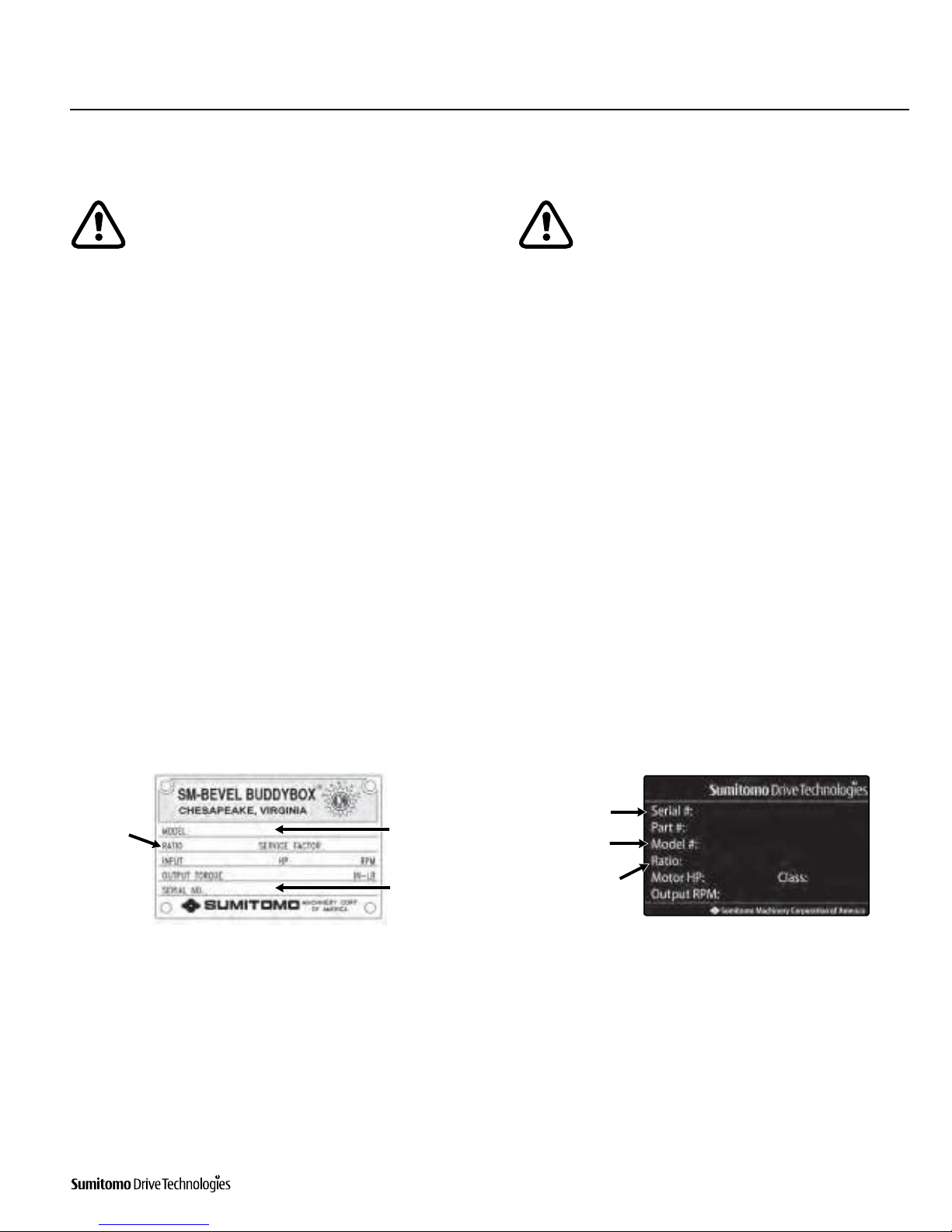
Nameplate Inspection
When contacting Sumitomo about this product, please be
prepared to provide the following information from the reducer/
gearmotor nameplate:
tSFEVDFSPSHFBSNPUPSNPEFMOVNCFSOPNFODMBUVSFtSFEVDUJPOSBUJPtTFSJBMOVNCFSLubrication Inspection
tOil lubricated units are shipped without oil,
unless the customer specified otherwise when
the unit was ordered. Always fill the unit with
the correct type and quantity of lubricant prior to
operation.
tCertain models must be filled with lubricant in
two separate locations, the Bevel Gear portion
(output) and the input portion.
Refer to the lubrication section in this manual for detailed
lubrication information.
Nominal
Reduction
Ratio
Unit Model
Number
Unit Serial
Number
TESA Nameplate
Nominal
Reduction
Ratio
Unit Serial
Number
Unit Model
Number
Metal Nameplate

Cyclo® BBB4
Type Prefix
Unit built with special mods S
Shrink Disc S
No special mods applied
Cyclo® BBB4
4Operation & Maintenance Manual4Operation & Maintenance Manual
Type of Input Reducer
Prefix
Gearmotor
Prefix
Gearmotor M
Free Input Shaft
w/ Input Adaptor J JM
w/Quill Adaptor X XM
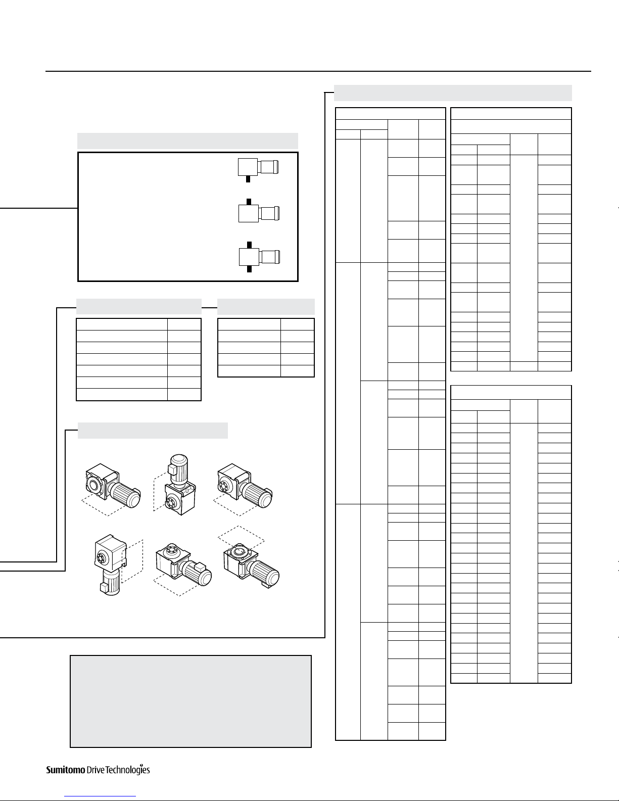
Nomenclature
Nomenclature
Motor Power
(applies only to
1750 RPM)
Modification
Output Shaft Orientation
Frame Size
Shaft Specifications
AGMA Class
#SBLF(FBSNPUPS0OMZInput Connection
Mounting Style
Modification (Special feature) Mounting position and optional specification (as required)
Input connection Gearmotor or Reducer Specification
Mounting style AGMA class (Gearmotor only)
Output shaft orientation Shaft specification
Cyclo® BBB4 product code (always“L”)
Motor Power
Symbol (1750 RPM)
Frame Size Brake Ratio
HP (kW) Symbol
1/8 (0.1) 01
1/4 (0.2) 02
1/3 (0.25) 03
1/2 (0.4) 05
3/4 (0.55) 08
1(0.75) 1
1.5 (1.1) 1H
2(1.5) 2
3(2.2) 3
5(3.7) 5
7.5 (5.5) 8
10 (7.5) 10
15 (11) 15
20 (15) 20
25 (18.5) 25
30 (22) 30
40 (30) 40
50 (37) 50
60 (45) 60
75 (55) 75
Single Reduction
4A100 4B125 4C170 4E175
4A105 4B140 4C175 4E180
4A110 4B145 4D160 4E185
4A115 4B160 4D165 4E190
4A120 4B165 4D170 4E195
4A125 4C140 4D175 4F180
4A140 4C145 4D180 4F185
4A145 4C160 4D185 4F190
4B120 4C165 4E170 4F195
Double Reduction
4A10DA 4B16DA 4C17DC 4E17DC
4A12DA 4B16DB 4D16DA 4E18DA
4A12DB 4B16DC 4D16DB 4E18DB
4A14DA 4C14DA 4D16DC 4E19DA
4A14DB 4C14DB 4D17DA 4E19DB
4A14DC 4C14DC 4D17DB 4F18DA
4B12DA 4C16DA 4D17DC 4F18DB
4B12DB 4C16DB 4D18DA 4F19DA
4B14DA 4C16DC 4D18DB 4F19DB
4B14DB 4C17DA 4E17DA
4B14DC 4C17DB 4E17DB
Type Prefix
Horizontal H
Vertical V
Vertical Up (Solid Shaft) W
Type Prefix
Shaft Mount (Hollow Shaft) Y
Housing U
Flange (Solid Shaft) F
Foot (Solid Shaft) H
Input
Shaft
Hollow Output
Shaft Suffix
mm Key (mm)
Inch Key (Inch) K
mm Taper-Grip® M
Inch Taper-Grip® Y
Class Suffix
I A
II B
III C
Suffix
With Brake B
No Brake
LHYMS 5 - 4 A 1 2 5 YY1 - B - 28
Output shaft direction (shafted model only)
B
Our nomenclature details specific information about our proucts. Verify that the nomenclature of the unit delivered matches your order.
Operation & Maintenance Manual 5
Cyclo® BBB4
Cyclo® BBB4
Nomenclature, continued
Gearmotor Specification Reducer Specification
Mounting Positions
Nomenclature Example:
LHYMS-5-4A125-YBY1-B-28
L- Cyclo® Bevel Buddybox
H- Horizontal
Y- Shaft Mount (Hollow Shaft)
M- Gearmotor
S- Special Modifications
5 - 5 HP (3.7kW), 1750 RPM
4A125 - Frame Size
Y- Inch Shaft Specification
B- AGMA Class
Y1 - Mounting Position
B- Brake (gearmotor only)
28 - Ratio
Specification Suffix
Three-Phase Motor
Single-Phase Motor SG
AF Motor (Adj. Frequency) AV
Servo Motor SV
DC Motor DV
Torque Limiter TL
Type Suffix
Standard
Baseplate BP
Shovel Base SB
DC Motor DV
Nominal and Exact Ratio
Y1
Projects to Left Side L
Projects to Right Side R
Projects to Both Left/Right Sides T
Output Shaft DirectionTIBGUFENPEFMPOMZY4
Y2 Y3
Y5
Y6
BBB with Planetary Input
Nominal Ratio Frame
Size
Exact
Ratio
Input Overall
3 11
4A10 10.50
4A12
4A14 10.89
4B14
4B16
10.85
4C16
4D16
4D17
4E17
4E18 10.50
4F18
4E19 10.82
4F19
4
13
4A10 12.99
4A12 12.80
4A14 12.95
4B14
4B16
12.804C16
4D16
4D17
13.09
4E17
4E18
4F18
4E19 13.01
4F19
14
4A10 14.21
4A12 14.00
4A14 14.16
4B14
4B16
14.004C16
4D16
4D17
14.32
4E17
4E18
4F18
4E19 14.23
4F19
5
16
4A10 15.36
4A12 15.65
4A14 16.00
4B14
4B16
16.264C16
4D16
4D17 16.17
4E17
4E18 15.63
4F18
4E19 15.47
4F19
18
4A10 16.80
4A12 17.12
4A14 17.50
4B14
4B16
17.784C16
4D16
4D17 17.68
4E17
4E18 17.10
4F18
4E19 16.92
4F19
BBB with Cyclo Input
Single Reduction
Nominal Ratio Frame
Size
Exact
Ratio
Input Overall
6 21
All
21.0
722 22.4
25 24.5
8 28 28.0
11 35 35.2
39 38.5
13 46 45.5
15 53 52.5
17 60 59.5
21 67 67.2
74 73.5
25 80 80.0
88 87.5
29 102 101.5
35 112 112.0
123 122.5
43 151 150.5
51 179 178.5
59 207 206.5
71 249 248.5
87 305 304.5
119 417 4A10 416.5
Double Reduction
Nominal Ratio Frame
Size
Exact
Ratio
Input Overall
104 364
All
364.0
121 424 423.5
143 501 500.5
165 578 577.5
195 683 682.5
231 809 808.5
273 956 955.5
319 1117 1116.5
377 1320 1319.5
473 1656 1655.5
559 1957 1956.5
649 2272 2271.5
731 2559 2558.5
841 2944 2943.5
1003 3511 3510.5
1247 4365 4364.5
1479 5177 5176.5
1849 6472 6471.5
2065 7228 7227.5
2537 8880 8879.5
3045 10658 10657.5
3481 12184 12183.5
4437 15530 15529.5
5133 17966 17965.5
6177 21620 21619.5
7569 26492 26491.5

Cyclo® BBB4
6Operation & Maintenance Manual Cyclo® BBB4
Storing and Transporting
Storage Location
t4UPSFUIFVOJUJOBDMFBOESZBSFBtDo not store outdoors or in an area with high humidity, dust,
sudden temperature changes, or corrosive gases.
Generally, the Cyclo® BBB4 gearbox is to be stored indoors, in an
ordinary factory or a warehouse. The unit should be sealed,
wrapped in plastic and additionally packed with desiccant.
Desiccant should be replaced periodically to keep the inside
of the box dry. Use of color changing desiccant will aid in
identifying when desiccant should be changed.
Storage Period
tDo not store the unit for longer than 3 months without
following long-term storage procedures recommended by
Sumitomo.
t$POTVMU4VNJUPNPXIFOTUPSJOHUIFVOJUGPSNPSFUIBOmonths. Rust proofing procedures are required.
t$POTVMU4VNJUPNPXIFOFYQPSUJOHUIFVOJU3VTUQSPPmOHprocedures may be required.
If the Cyclo® BBB4 gearbox will be inactive for a long period of
time, long-term storage preparation is required to prevent rust
or other degradation to the gearbox.
LONG-TERM STORAGE SPECIFIED WITH ORDER:
If long-term storage is specified at the time of order entry, Shell
VSI Circulating Oil #32 or NP-20 [JIS] equivalent rust preventative
is already sprayed into the Cyclo® BBB4 reducer and the air vent is
replaced with a sealing plug before shipping the reducer from
Sumitomo factory. External machined surfaces are coated with a
suitable NP-19 [JIS] petroleum base corrosion preventative such
as Black Bear Par-Al-Ketone, Houghton Rust Veto 342, Daphne
Ever Coat No.1 or equivalent.
Consult Sumitomo for Long Term Storage procedures:
t4UPSBHFXJUIPVUGBDUPSZQSFQBSBUJPOTt0OHPJOHNBJOUFOBODFEVSJOHTUPSBHFQFSJPEOperation After Storage
Before operating the unit after an extended storage period, flush
unit of rust preventative and ensure that non-metal parts, i.e., oil
seals, o-rings, air breather, have not deteriorated. Non-metal parts
may deteriorate easily from exposure to ambient conditions (i.e.,
extreme temperatures, UV rays). Replace deteriorated parts with
new before unit start-up.
After starting the unit, verify that there is no abnormal noise,
vibration, and/or temperature rise. Immediately stop the unit and
call your local distributor, Original Equipment Manufacturer or
Sumitomo directly if you observe any abnormality.
Transporting
tDo not stand directly under a unit suspended by a
lifting mechanism. Injury or death may occur if the
unit is dropped.
tBefore lifting the unit, determine its weight (refer
to catalog, packing list, etc.) and ensure that the
moving equipment will support the unit’s weight.
tNever hoist or move a unit that exceeds the
moving equipment’s rated capacity or else
personal injury and/or equipment damage may
occur.
tDo not allow the unit to drop or fall while moving.
Always use the eye bolts attached to the gear
housing (and on motor if supplied) when moving
the unit. After securing the unit to the machine,
remove the moving hooks/straps from the
eyebolts.
Operation & Maintenance Manual 7
Cyclo® BBB4
Cyclo® BBB4
Installation Notes
Installation Precautions
t%POPUVTFUIFSFEVDFSHFBSNPUPSGPSTQFDJmDBUJPOTother than those shown on the nameplate or in the
manufacturing specification documents. Personal
injury and/or equipment damage may occur.
t%POPUQMBDFDPNCVTUJCMFNBUFSJBMPOPSBSPVOEthe unit; fire may occur.
t%POPUQMBDFBOZPCKFDUTBSPVOEUIFVOJUUIBUXJMMprohibit proper ventilation. Inadequate ventilation
may lead to high unit temperature and/or fire.
t%POPUTUFQPOPSIBOHGSPNUIFVOJU&YDFTTJWFweight may cause component breakage leading to
personal injury and/or equipment damage.
t%POPUUPVDIUIFTIBGULFZXBZPSNPUPSGBOXJUIbare hands; injury may occur.
t'PSBQQMJDBUJPOTJOXIJDIMVCSJDBOUMFBLTDPVMEBEWFSTFMZBõFDUPQFSBUJPOTJFQBDLBHFIBOEMJOHfood processing), place an oil pan below the unit to
protect against contamination that may occur if oil
seals become damaged or worn.
t%POPUSFNPWFUIFFZFCPMUGSPNUIFNPUPS4IPVMEthe eye-bolt need to be removed for any reason,
install a replacement bolt in the tapped hole to
prevent water from entering the motor.
Installation Location
Ambient Temperature Range: 14° - 104°F (-10° - 40°C)
Ambient Humidity: 85% or less
Ambient Conditions: 14°F minimum
Altitude: 3,280 feet (1,000 m) or less
Atmosphere: The location should not contain corrosive gas,
explosive gas, or steam. The location should be free
of dust and well ventilated.
Location: Indoor – free of dust and water
Consult Sumitomo when the unit will operate in conditions other
than those specified above. Special unit modifications may be
required.
Units manufactured according to customer specified application
requirements (i.e. outdoor modifications, high-temperature
modifications) are designed to operate within the specified
environment.
Install the unit so inspection and/or maintenance procedures may
be easily performed. Install all units that are not shaft mounted
on a sufficiently rigid base.
Torque arm clearance with machine structure is required to allow
for machine shaft run out. Refer to the Torque Arm Installation
section in this manual for additional information.
Installation Angle
Mount the unit in the specified position for which it was
ordered. Confirm the mounting position from the gearbox
nameplate.
Consult your local distributor, Original Equipment Manufacturer
or Sumitomo directly if the mounting angle is to be other than
horizontal or vertical.
Severe Loading Conditions
For applications with severe vibration and/or frequent starts and
stops, Sumitomo recommends the use of high-strength mounting
bolts of Grade 8.8 (or greater).
Installation onto the Driven Machine
t#FGPSFDPVQMJOHUIFSFEVDFSHFBSNPUPSUPUIF
machine, verify the appropriate/desired rotation of
UIFNBDIJOF%JõFSFODFTJOUIFSPUBUJPOBMEJSFDUJPOmay cause personal injury and/or equipment dam-
age.
t#FGPSFPQFSBUJOHUIFVOJUFOTVSFUIBUBMMTBGFUZguards around the rotating components are
in-place and secure. Failure to do so may result in
personal injury.
t8IFOKPJOJOHUIFSFEVDFSPSHFBSNPUPSUPUIFMPBEensure that the center alignment, belt tension, and/
or parallelism of the coupling device are within the
coupling manufacturer’s established recommendations.
For applications with a belt, ensure that the belt is
properly tensioned to the manufacturer’s specification,
and the bolts securing the pulley and couplings
are sufficiently tightened. Failure to follow these
precautions may result in personal injury and/or
equipment damage.
8Operation & Maintenance Manual
Cyclo® BBB4
Cyclo® BBB4
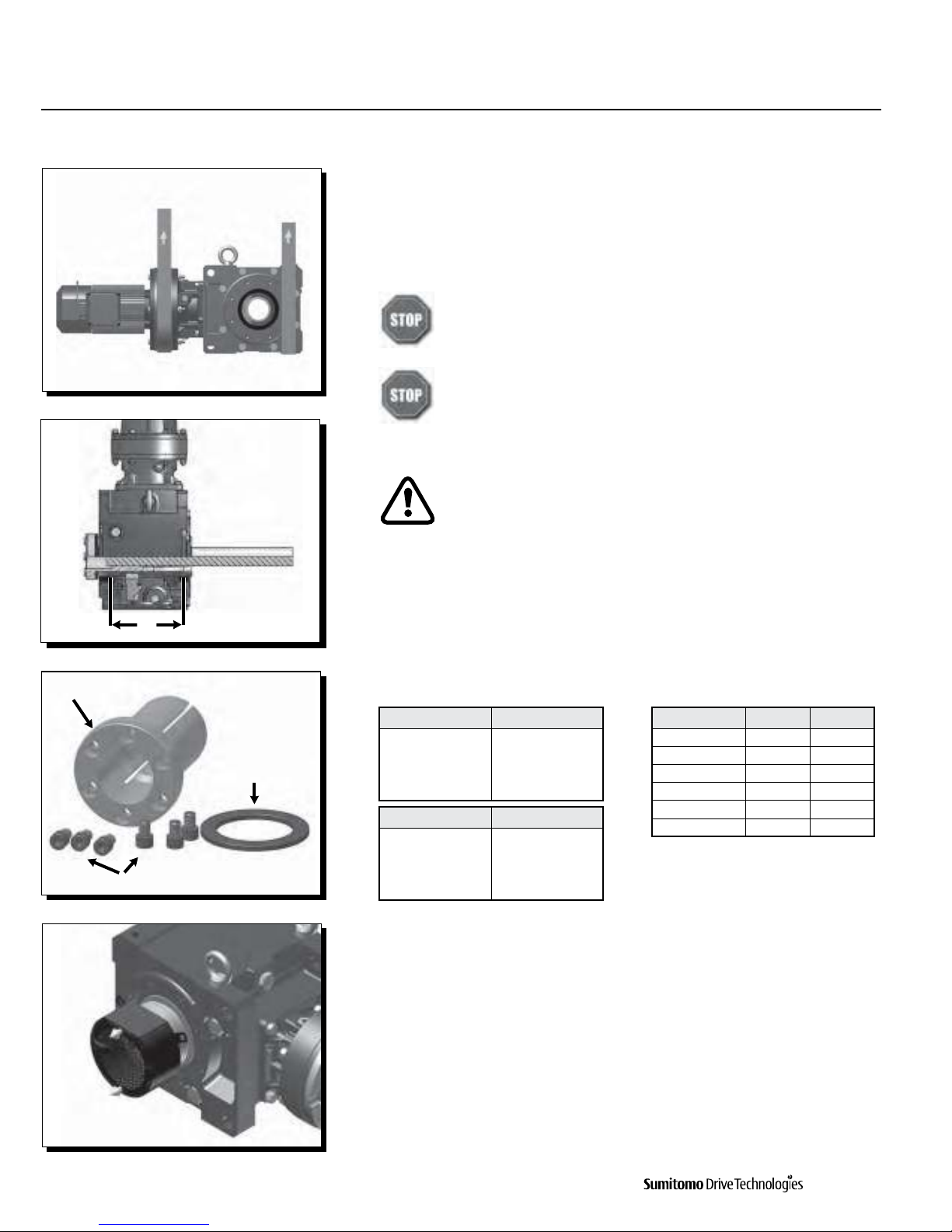
Installation onto Driven Shaft
Taper-Grip® Bushing
Taper-Grip® Bushing Introduction
The keylessTaper-Grip® bushing system provides a simple and reliable shaft attachment
for Sumitomo speed reducers and gearmotors. This system allows bi-directional shaft
rotation operation with a powerful, slip-free grip.To assure peak performance of your
equipment, please read, understand and follow these installation instructions.
Prior to installation of the Cyclo® BBB4 onto the driven shaft, ensure that
the shaft length meets or exceeds the minimum shaft engagement value
“TT” detailed in Table 1.
Do not operate unit until the torque arm has been attached to the unit
and fixed to a rigid structure. The torque arm prevents counter-rotation
during unit operation. Refer to torque arm installation section in this
manual for instructions.
CAUTION: The Cyclo® BBB4 must be externally supported prior to
insertion of driven shaft into bushing. External support MUST be
maintained until all bushing socket head cap screws have been
tightened to the appropriate operational torque.
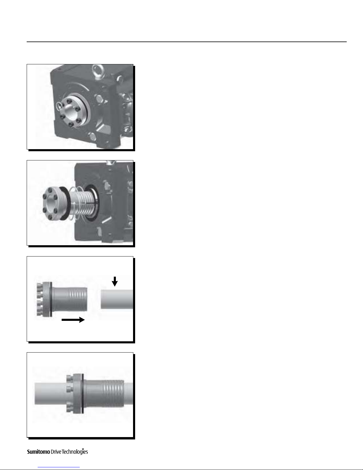
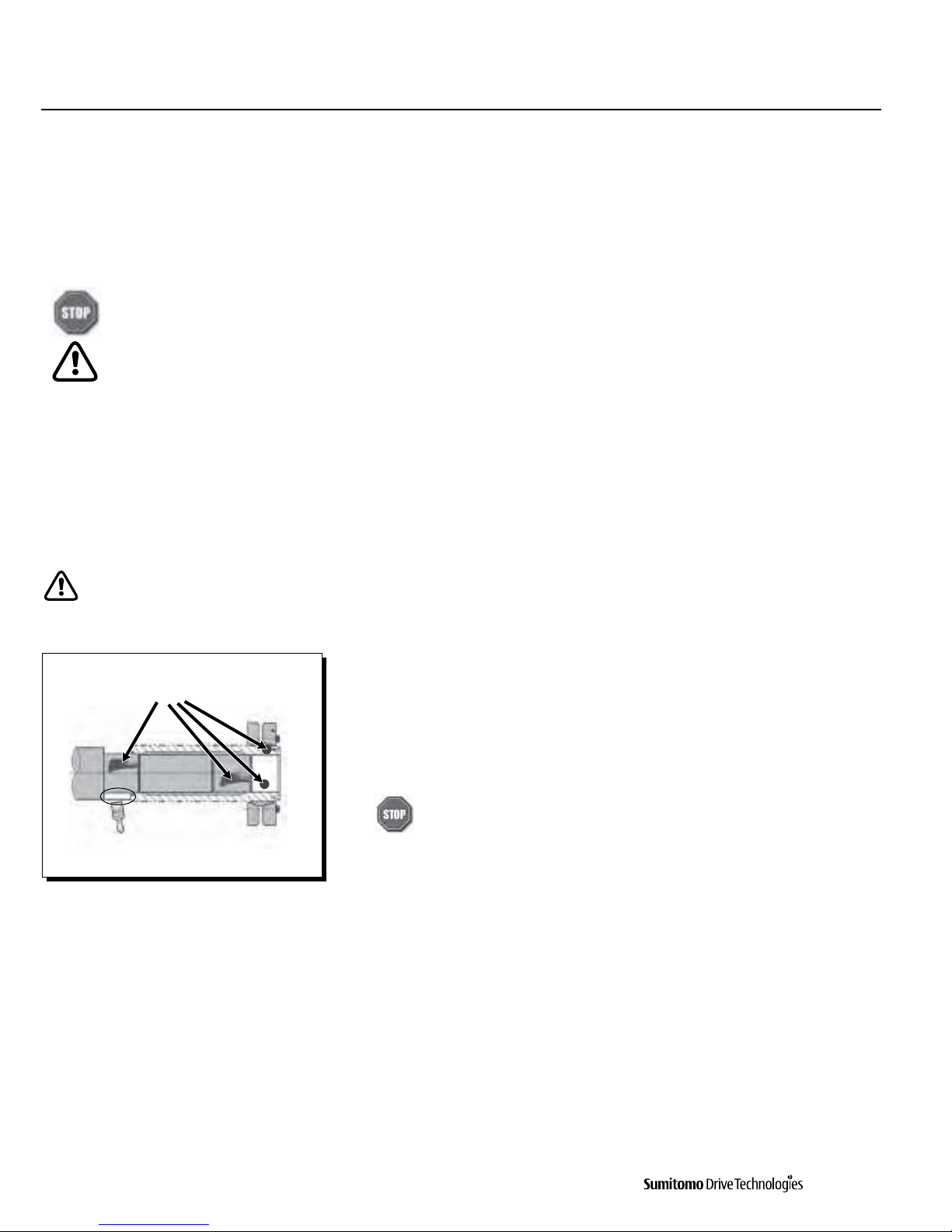
Components of Taper-Grip® Bushing
As shown in the figure on the left, the Taper-Grip® bushing includes the bushing,
thrust collar, and socket head cap screws.
Table 1. Driven Shaft Tolerance [1] and Minimum Shaft Engagement
Taper-Grip® Bushing Installation onto Driven
Shaft
1
Remove bushing cover if unit was supplied with one.
Taper-Grip® Bushing
Socket Head Cap Screws
Thrust Collar
TT 4IBGU%JBNFUFSJO5PMFSBODFJO1-3/16 – 1-15/16 +0 / -0.0015
2 – 3-1/8 +0 / -0.0018
3-3/16 – 4-11/16 +0 / -0.0021
4-3/4 – 6-1/2 +0 / -0.0025
Cyclo® BBB4 Size 55JOTT (mm)
4A 7.79 (198)
4B 9.33 (237)
4C 10.16 (258)
4D 11.82 (300)
4E 13.94 (354)
4F 16.22 (412)
Shaft Diameter (mmTolerance (μm)
(30 - 50) (+0 / -39)
(50 - 80) (+0 / -46)
(80 - 120) (+0 / -54)
(120 - 180) (+0 / -63)
Note: [1] Based on ISO/JIS/DIN h8
Cyclo® BBB4
Operation & Maintenance Manual 9
Cyclo® BBB4
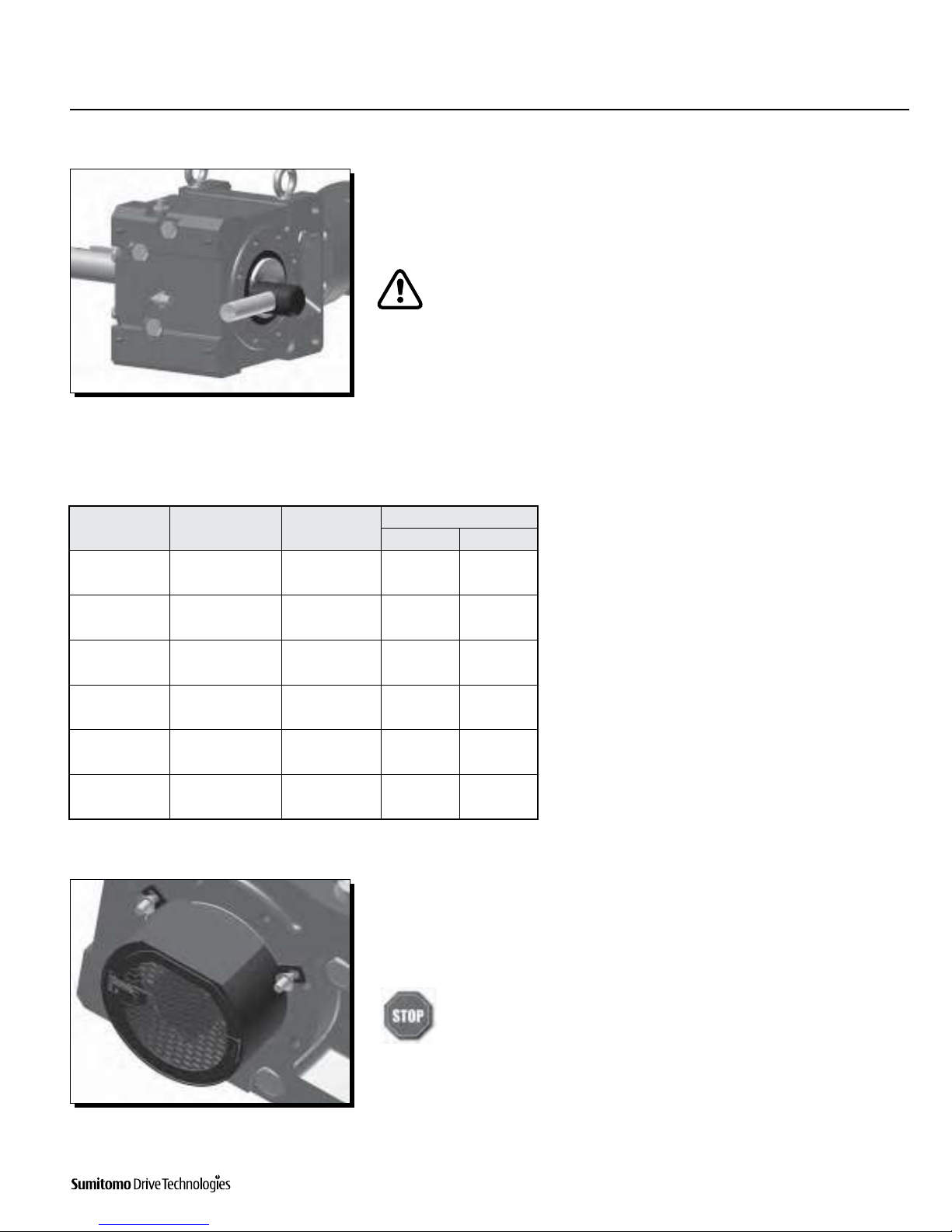
Installation onto Driven Shaft, continued
Taper-Grip® Bushing
Clean Driven
Shaft
2
Loosen socket head cap screws.
3
Remove (unscrew) Taper-Grip® bushing from the unit.
4
Clean all grease, oil and/or anti-seize grease from the driven shaft. Failure to do so
could result in damage to shaft.
Slide Taper-Grip® bushing onto driven shaft.
5
Inspect and test Taper-Grip® bushing on shaft.
t$IFDLTIBGUGPSburrs, corrosion, or warpage. Repair or replace shaft
as necessary.
t4MJEFCVTIJOHCBDLBOEGPSUIBMPOHTIBGUDIFDLJOHGPSTVSGBDFJSSFHVMBSJUJFT
and fit.
t7FSJGZCVTIJOHJTTJ[FEDPSSFDUMZGPSUIFTIBGUEJBNFUFS

10 Operation & Maintenance Manual
Cyclo® BBB4
Cyclo® BBB4
Installation onto Driven Shaft, continued
Taper-Grip® Bushing
Apply thin layer of
anti-seize grease to male
threads of bushing only.
Do not apply anti-seize
grease to the female
threads in the hub.
6
Remove Taper-Grip® bushing from driven shaft.
7
Apply a thin layer of anti-seize grease to the male threads of the Taper-Grip®
bushing only.
Ensure that the anti-seize grease does not enter the Taper-Grip®
bushing bore.
Do not apply anti-seize grease to the female threads in the hub.
8
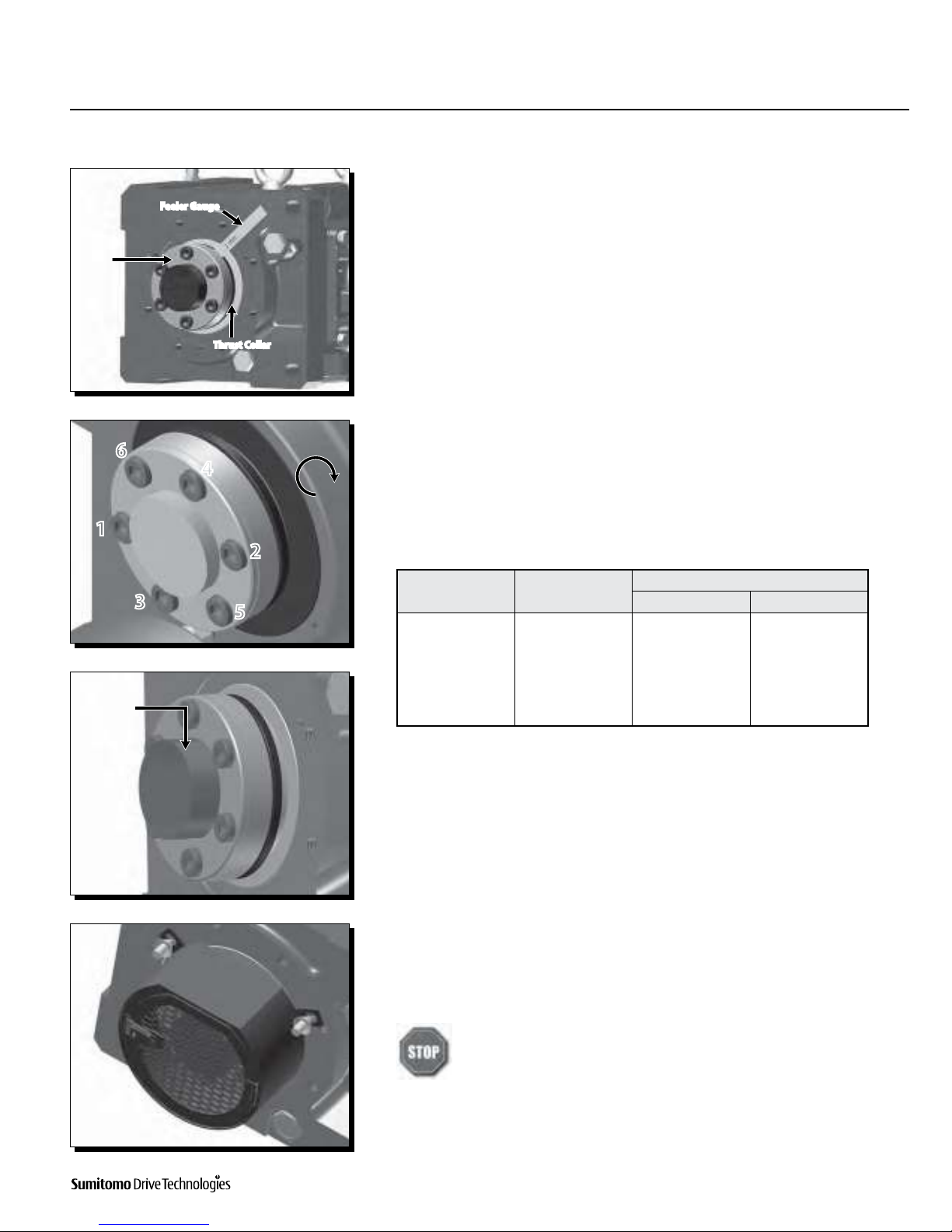
Screw Taper-Grip® bushing into Cyclo® BBB4 leaving approximately 1 mm gap
between the bushing flange and thrust collar.
Do not apply grease, oil, or anti-seize grease to the driven shaft or the
bushing bore before placing the unit onto driven shaft. Use of these friction-
NJOJNJ[JOHQSPEVDUTXJMMBEWFSTFMZBõFDUUIFBCJMJUZPGUIFVOJUUPUSBOTNJUtorque.
CAUTION: The Cyclo® BBB4 must be externally supported prior to insertion
of driven shaft into bushing. External support MUST be maintained until all
bushing socket head cap screws have been tightened to the appropriate
operational torque.
9
Mount or slide the Cyclo® BBB4 onto the driven shaft to the desired location.
Do not rock or pry the unit.
Cyclo® BBB4
Operation & Maintenance Manual 11
Cyclo® BBB4
Installation onto Driven Shaft, continued
Taper-Grip® Bushing
Bushing
Flange
Feeler Gauge
Thrust Collar
1
64
2
5
3
Apply grease
to exposed
portion of
driven shaft.
10
Screw Bolts into Taper-Grip® bushing.
t-JHIUMZPJMUISFBETPGFBDICPMUCFGPSFJOTFSUJOHt'JOHFSUJHIUFOFBDICPMUUPTFDVSFJOQMBDFt#FTVSFUPmaintain the 1 mm (approximate) gap between the thrust collar
and the bushing flange.
11
Tighten bushing bolts to the correct torque value.
t'PMMPXJOHBTUBSQBUUFSOVTFBUPSRVFXSFODIUPgradually tighten each socket
head cap screw in 20% increments.
t3FGFSUPTable 2, Taper-Grip® Bushing Bolt Tightening Torques, for the correct
operational screw torques.
Table 2. Taper-Grip® Bushing Bolt Tightening Torques
12
In order to prevent corrosion, apply grease to the exposed portion of the driven shaft.
tAfter installing and tightening the bushing bolts with a torque wrench, apply
grease or an anti-corrosion product to the exposed portion of the shaft.
13
For units that include a bushing safety cover, reinstall the guard over the
Taper-Grip® bushing.
Do not operate unit until the torque arm has been attached to the unit and
fixed to a rigid structure. The torque arm prevents counter-rotation during
unit operation. Refer to torque arm Installation section in this manual for
instructions.
Cyclo® BBB4 Size Screw Qty x Size
Screw Torque
MCtGU/tN4A 6 x M12 56 (75)
4B 6 x M12 104 (140)
4C 6 x M16 185 (250)
4D 6 x M16 223 (300)
4E 8 x M16 223 (300)
4F 10 x M16 223 (300)
12 Operation & Maintenance Manual
Cyclo® BBB4
Cyclo® BBB4
Installation onto Driven Shaft, continued
Keyed Hollow Bore
Keyed Hollow Bore Installation
Do not operate unit until the torque arm has been attached to the unit and fixed to a rigid structure. The torque arm prevents
counter-rotation during unit operation. Refer to torque arm Installation section in this manual for instructions.
CAUTION: The Cyclo® BBB4 must be externally supported prior to insertion of driven shaft into hollow bore.
Bore and Shaft Tolerance Specifications
t6OMFTTPUIFSXJTFTQFDJmFEUIFUPMFSBODFPGUIF)PMMPX4IBGU#PSFDPOGPSNTUP+*4)t*GBQQMJDBUJPOJOWPMWFTIJHITIPDLMPBEJOHBOEPSMBSHFSBEJBMMPBETBTIBGUUPMFSBODFPG+*4KTPS+*4LJTSFDPNNFOEFEGrease
Keyed Hollow Bore Installation
onto Driven Shaft
1
Apply anti seize compound to the driven shaft surface and inside the reducer keyed
hollow bore.
2
Align the driven shaft with the reducer/gearmotor bore and carefully slide unit onto
the driven shaft to the desired location.
If the fit is tight, strike on the keyed hollow bore with a wooden or hard rubber
mallet to assist in the assembly.
If using a mallet during installation, strike only against the unit’s steel keyed
hollow bore. Do not strike the reducer housing or oil seal as damage to the
bearings, housing and/or seals may occur.
Note: If the fit is tight, use a jig such as the one shown in Table 3 to ease
assembly. Sumitomo does not supply a mounting jig. This information
is provided for reference only.
3
Once driven shaft has been completely inserted into the unit’s keyed hollow bore,
secure the shaft in place using a keeper plate as shown to the left, or some other
means of securing the unit to the driven shaft.
Do not operate unit until the torque arm has been attached. Refer to
the Torque Arm Installation section in this manual for instructions.
Cyclo® BBB4
Operation & Maintenance Manual 13
Cyclo® BBB4
Installation onto Driven Shaft, continued
Keyed Hollow Bore
Size a b c d e
$$*40+*4A2 Bearing Nut Threaded Rod
4A 3 25 51104 M16 M16 x 250
4B 65 25 51105 M20 M20 x 300
4C 75 25 51105 M20 M20 x 300
4D 85 35 51107 M24 M24 x 400
4E 100 35 51107 M24 M24 x 400
4F 120 46 51109 M30 M30 x 450
5BCMF+JH%JNFOTJPOT(mm)
Spacer b
Retaining Ring a
Ball
Bearing
c
Threaded Rod e Nut d
A2
14 Operation & Maintenance Manual
Cyclo® BBB4
Cyclo® BBB4
Shrink Disc Type Mounting Introduction
The keyless Shrink Disc provides a reliable commodity shaft attachment for Sumitomo speed reducers and gearmotors. This system allows
bi-directional shaft rotation operation with a powerful, slip-free grip.
To assure peak performance of your equipment, please read, understand and follow these installation instructions.
Do not operate unit until the torque arm has been attached to the unit and fixed to a rigid structure. The torque arm prevents
counter-rotation during unit operation. Refer to torque arm Installation section in this manual for instructions.
CAUTION: The Cyclo® BBB4 must be externally supported prior to insertion of driven shaft into hollow bore. External support
MUST be maintained until all shrink disc socket head cap screws have been tightened to the appropriate operational torque.
Bore and Shaft Tolerance Specifications
t3FGFSUPUIFDFSUJmFEPVUMJOFESBXJOHPS$ZDMP¥###$BUBMPHGPSSFDPNNFOEFENBDIJOFTIBGUEJNFOTJPOTt6OMFTTPUIFSXJTFTQFDJmFEUIFUPMFSBODFPGUIF4ISJOL%JTD#PSFDPOGPSNTUP+*4)t*GBQQMJDBUJPOJOWPMWFTIJHITIPDLMPBEJOHBOEPSMBSHFSBEJBMMPBETBTIBGUUPMFSBODFPG+*4KTPS+*4LJTSFDPNNFOEFEShrink Disc Type Hollow Bore Installation onto Shaft
Before placing unit onto driven shaft, do not apply grease, oil, or anti-seize grease to the entire driven shaft or to the bore of
the shrink disc. 6TFPGUIFTFGSJDUJPONJOJNJ[JOHQSPEVDUTXJMMBEWFSTFMZBõFDUUIFBCJMJUZPGUIFVOJUUPUSBOTNJUUPSRVFInstallation onto Driven Shaft, continued
Shrink Disc Type Hollow Bore
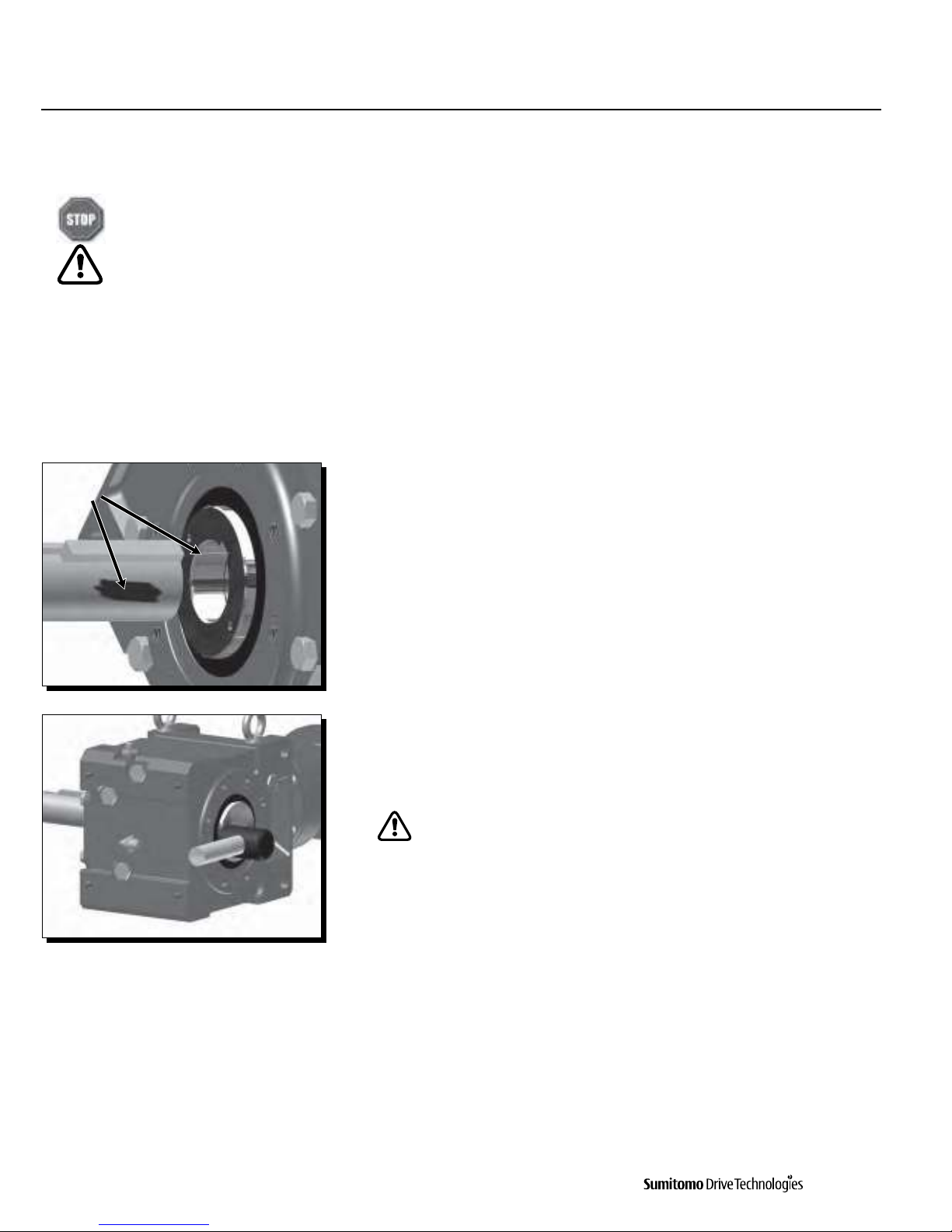
1
Clean and degrease contact surfaces; reducer shaft and bore, and the machine
driven shaft.
Apply Molykote 321 or an equivalent dry film lubricant to the driven shaft shoulder
opposite from the shrink disc.
Do Not apply any friction minimizing compound to the driven shaft at or
near the shrink disc.
Degrease
these areas
Apply Molykote 321
to this shaft area only
Cyclo® BBB4
Operation & Maintenance Manual 15
Cyclo® BBB4
Installation onto Driven Shaft, continued
Shrink Disc Type Hollow Bore
Size Model
5ZQJDBMBolt Bolt Torque
MCtGU/tN4A TAS-3071-55x68 10 x M6x25
ISO/JIS grade 10.9 9(12)
4B TAS-3071-65x80 7 x M8x30
ISO/JIS grade 12.9 26 (34)
4C TAS-3071-75x100 12 x M8x35
ISO/JIS grade 12.9 26 (34)
4D TAS-3071-85x110 9 x M10x40
ISO/JIS grade 12.9 51 (68)
4E TAS-3071-100x140 10 x M12x45
ISO/JIS grade 12.9 87 (118)
4F TAS-3071-120x165 8 x M16x55
ISO/JIS grade 12.9 214 (290)
Table 4. Shrink Disc Bolt Tightening Torques
4
For units with a safety cover, install the guard over the shrink disc.
Do not operate unit until the torque arm has been attached. Refer to the
Torque Arm Installation section in this manual for instructions.
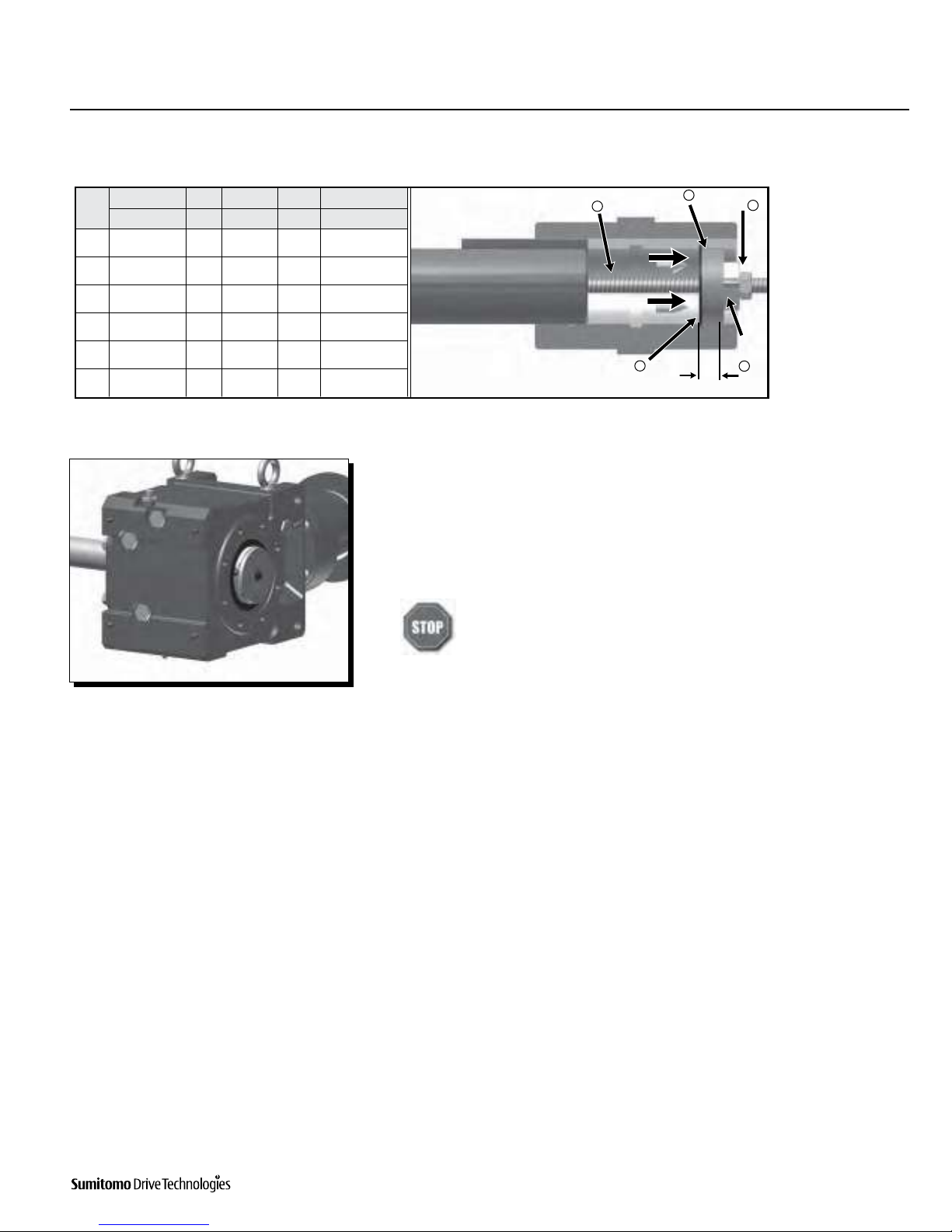
3t4FUUIFVOUJHIUFOFETISJOLEJTDPOUIFSFEVDFSshaft.
t'PSQJFDFEFTJHOTISJOLEJTDNBLFTVSFUIBUboth plates are parallel when tightening bolts.
t"GUFSDPOmSNJOHUIBUUIFTISJOLEJTDJTTFU
correctly, tighten the bolts uniformly, in a
clockwise pattern while keeping both plates
parallel (not diagonally or ‘star’ pattern).
t*UJTSFDPNNFOEFEUPUJHIUFOSFTQFDUJWFCPMUTCZ30 degrees each time – until the specified torque
is reached.
2
Align the driven shaft with the bore of reducer/gearmotor bore and carefully slide unit
onto the driven shaft to the desired location.
t*GUIFmUJTUJHIUTUSJLFPOUIFSFEVDFSIPMMPXCPSFXJUIBXPPEFOPSIBSESVCCFSmallet to assist in the assembly.
If using a mallet during installation, strike only against the unit’s steel
hollow bore. Do not strike the reducer housing or oil seal, as damage to the
bearings, housing, and/or seals may occur.
If the fit is tight, use a jig such as the one shown in the Keyed Hollow Bore
Installation section to ease assembly. Sumitomo does not supply a
mounting jig. This information is provided for reference only.
16 Operation & Maintenance Manual
Cyclo® BBB4
Cyclo® BBB4
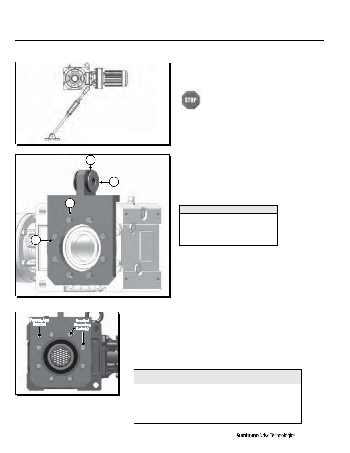
Torque Arm Installation
5PSRVF"SN*OUSPEVDUJPO'MBOHF.PVOU#BOKP5ZQF5PSRVF"SN1
2
4
3
Torque Arm
Bracket Bracket
Mounting
#PMUTTBracket
Bolt Size[1]
Torque
MCtGU/tN4A 8 x M10 34 – 38 (46 – 51)
4B 8 x M12 59 – 65 (80 – 88)
4C 8 x M16 152 – 167 (206 – 227)
4D 8 x M20 290 – 319 (392 – 431)
4F 8 x M24 507 – 558 (686 – 755)
Item Number Description
1 Torque Arm Bracket
2 Bracket Hardware
3 Rubber Bushing (qty 3)
4 Washer (qty 2)
5BCMF'MBOHF.PVOU#BOKP5ZQFTorque Arm Components
5BCMF'MBOHF.PVOU#BOKP5PSRVF"SN#PMU5JHIUFOJOHNote: [1] Bolt ISO/JIS Class 8.8
Torque Arm Introduction
A torque arm is a device used to prevent counter-rotation of the
shaft mounted reducer/gearmotor during operation.
The torque arm must be mounted in tension when
torque arm mounting point is greater than 6 inches
(150mm) from machine mounting point or, tie-rod or
turn buckle type torque arm is used.
Sumitomo Supplied Components of
'MBOHF.PVOU#BOKP5ZQF5PSRVF"SN'MBOHF.PVOU#BOKP5ZQF5PSRVF"SNInstallation Procedure
1
Attach the Flange Mount (Banjo) Torque Arm Bracket to the Cyclo® BBB4 using
mounting hardware.
Torques
Unit Size

Cyclo® BBB4
Operation & Maintenance Manual 17
Cyclo® BBB4
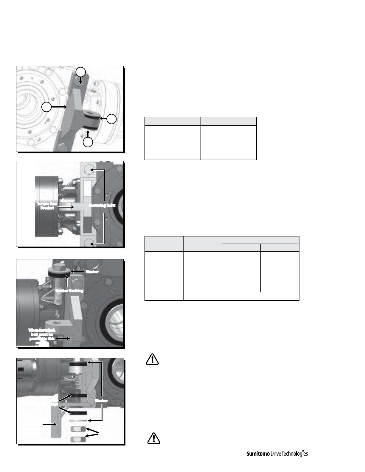
2
Place washer and rubber bushing on bolt.
Insert torque arm bolt (supplied by customer) through mounting tab on Banjo
torque arm.
Make sure bolt is parallel to Flange Mount (Banjo) Type Torque Arm surface
when fully installed.
3
Follow these steps to attach the customer supplied mounting bracket.
t1MBDFSVCCFSCVTIJOHBOENPVOUJOHBOHMFCSBDLFUPOCPMUt7FSJGZUIBUUIFNPVOUJOHBOHMFCSBDLFUIPMFJTUIFDPSSFDUEJBNFUFSTFF5BCMFin Step 1).
t1MBDFSFNBJOJOHCVTIJOHXBTIFSBOEUXPOVUTPOUIFCPMUDo not over-tighten nuts. Tighten to point where rubber bushings can
still be hand rotated.
4
Confirm that the rubber bushings can still be rotated by hand. This indicates the
bushing has not been over tightened.
Compressed bushings will not allow the bushings to properly absorb the
loads of the shaft mounted gearbox. This can lead to premature failure.
Mounting Angle Bracket must be secured to the machine structure.
5
Confirm the mounting angle bracket
does not interfere with the torque
arm. There should be no metal-to-
metal contact between the two during
a complete revolution of the driven
equipment.
Metal-to-Metal contact
between these two components
may lead to catastrophic failure
of the reducer/gearmotor.
Torque Arm Installation, continued
'MBOHF.PVOU#BOKP5ZQF5PSRVF"SNWhen installed,
bolt must be
parallel to this
surface
Rubber
Bushing
Washer
Washer
Mounting Angle
#SBDLFU$VTUPNFS4VQQMJFERubber Bushings
Nuts
$VTUPNFS4VQQMJFEDuring full rotation of driven shaft, there must be
no metal-to-metal contact between mounting angle
bracket and torque arm.
Unit Size Bracket Tab Bore Typical Bolt Size [1]
4A Ø18mm M16
4B Ø18mm M16
4C Ø22mm M20
4D Ø26mm M24
4E Ø33mm M30
4F Ø39mm M36
5BCMF'MBOHF.PVOU#BOKP5PSRVF"SN#PMU%JNFOTJPOTNote: [1] Bolt class should be greater or equal to ISO/JIS Class 8.8. Application with multiple start/stops and/or shock
loading should use ISO/JIS 10.9 at a minimum.
Torque Arm Bolt
$VTUPNFS
4VQQMJFE
18 Operation & Maintenance Manual
Cyclo® BBB4
Cyclo® BBB4
T-Type Torque Arm
Sumitomo Supplied Components for T-Type
Torque Arm
T-Type Torque Arm Installation Procedure
1
Attach the T-Type Torque Arm Bracket to the Cyclo® BBB4 using the supplied
mounting hardware.
Tighten mounting bolts according to the values listed in Table 9:
Table 9. T-Bracket Bolt Torques
2
Place washer and rubber bushing on bolt.
Insert torque arm bolt (supplied by customer) through mounting tab on Banjo
torque arm.
Make sure bolt is parallel to T-Type Torque Arm side when fully installed.
3
Follow these steps to attach the mounting angle bracket:
t1MBDFSVCCFSCVTIJOHBOENPVOUJOHBOHMFCSBDLFUPOCPMUt7FSJGZUIBUUIFNPVOUJOHBOHMFCSBDLFUIPMFJTUIFDPSSFDUEJBNFUFSGPSDVTUPNFSsupplied bolt.
t1MBDFSFNBJOJOHCVTIJOHXBTIFSBOEUXPOVUTPOUIFCPMUDo not over-tighten nuts. Tighten to point where rubber bushings can
still be hand rotated.
Torque Arm Installation, continued
T-Type Torque Arm
1
2
3
4
Torque Arm
Bracket
Mounting Bolts
Washer
Rubber Bushing
When installed,
bolt must be
parallel to this
surface
Nuts
$VTUPNFS4VQQMJFERubber Bushings Washer
Mounting Angle
Bracket
$VTUPNFS4VQQMJFEItem Number Description
1 Torque Arm Bracket
2 Bracket Hardware
3 Rubber Bushing (qty 3)
4 Washer (qty 2)
BBB4 Size Bracket
Bolt Size[1]
Torque
MCtGU/tN4A 2 x M16 152 – 167 (206 – 227)
4B 2 x M20 290 – 319 (392 – 431)
4C 2 x M24 507 – 558 (686 – 755)
4D 2 x M24 1014 – 1115 (1373 – 1510)
4E 2 x M24 1014 – 1115 (1373 – 1510)
4F T-Type Not Available
Table 8. T-Type Torque Arm Components
Note: [1] Bolt ISO/JIS Class 8.8

Cyclo® BBB4
Operation & Maintenance Manual 19
Cyclo® BBB4
Torque Arm Installation, continued
T-Type Torque Arm
Top View
4
Confirm that the rubber bushings can still be rotated by hand. This indicates the
bushing has not been over tightened.
Compressed bushings will not allow the bushings to properly absorb the
loads of the shaft mounted gearbox. This can lead to premature failure.
Mounting angle bracket must be secured to the machine structure.
5
Confirm the mounting angle bracket does not interfere with the torque arm.
There should be no metal-to-metal contact between the two during a complete
revolution of the driven equipment.
Metal-to-Metal contact between these two components may lead to
catastrophic failure of the reducer/ gearmotor.
Other manuals for Cyclo BBB4
5
Table of contents


