TABLE OF CONTENTS
1000URX RECEIVER VIEW .............................................................................................. i
INTRODUCTION .............................................................................................................. ii
RECEIVER (1000URX) SETUP ....................................................................................... 1
Powering the 1000URX .................................................................................................... 1
Mounting the 1000URX .................................................................................................... 1
Attaching the antennas to the 1000URX .......................................................................... 2
Connecting an Output cable between the 1000URX and camera .................................... 2
Setting the receiving frequency on the 1000URX ............................................................. 2
USING THE 1000URX RECEIVER’S CONTROLS AND DISPLAY ................................. 3
Power ............................................................................................................................... 3
Output .............................................................................................................................. 3
Monitor ............................................................................................................................. 3
LCD Display .....................................................................................................................3
THE 1000URX\AB ............................................................................................................4
THE 1000URX\Si ............................................................................................................. 4
THE 1000BT TRANSMITTER .......................................................................................... 5
Powering the 1000BT Transmitter .................................................................................... 5
SETTING THE TRANSMITTING FREQUENCY ON THE 1000BT .................................. 6
USING THE 1000BT TRANSMITTER’S CONTROLS AND DISPLAY ............................ 6
Power ............................................................................................................................... 6
Audio ................................................................................................................................ 6
MIC................................................................................................................................... 7
Input Level Adjustment ..................................................................................................... 7
Belt Clip ............................................................................................................................ 7
Antenna ............................................................................................................................ 7
Display ............................................................................................................................. 7
THE 1000XT .................................................................................................................... 8
Powering the 1000XT Transmitter .................................................................................... 9
SETTING THE TRANSMITTING FREQUENCY ON THE 1000XT .................................. 9
USING THE 1000XT TRANSMITTER’S CONTROLS AND DISPLAY .......................... 10
Power ............................................................................................................................. 10
Audio .............................................................................................................................. 10
MIC Connector /Locking Ring......................................................................................... 10
Input Level Adjustment ................................................................................................... 11
Display ........................................................................................................................... 11
SPECIFICATIONS ........................................................................................... Back page
LICENSING ...................................................................................................... Back page
iii 9
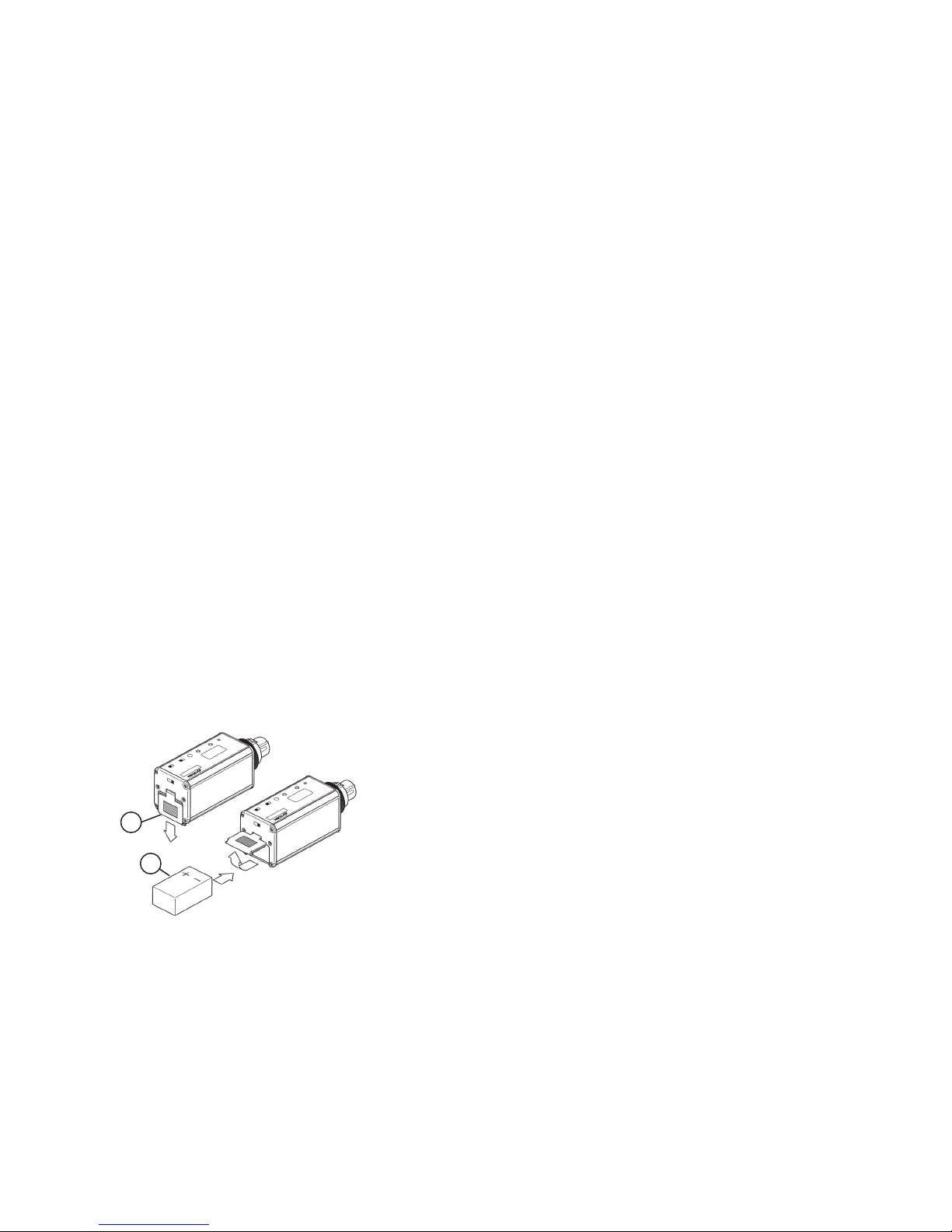
POWERING THE 1000XT TRANSMITTER
The 1000XT uses a single Alkaline 9V battery for power. The battery is
placed in the battery compartment by sliding the battery compartment
door [c] down and placing the battery in the compartment as shown
in the illustration [d]. The compartment is designed to allow the bat-
tery to be inserted only one way - with the correct polarity. DO NOT
FORCE THE BATTERY INTO THE COMPARTMENT. Azden does not
recommend the use of rechargeable batteries.
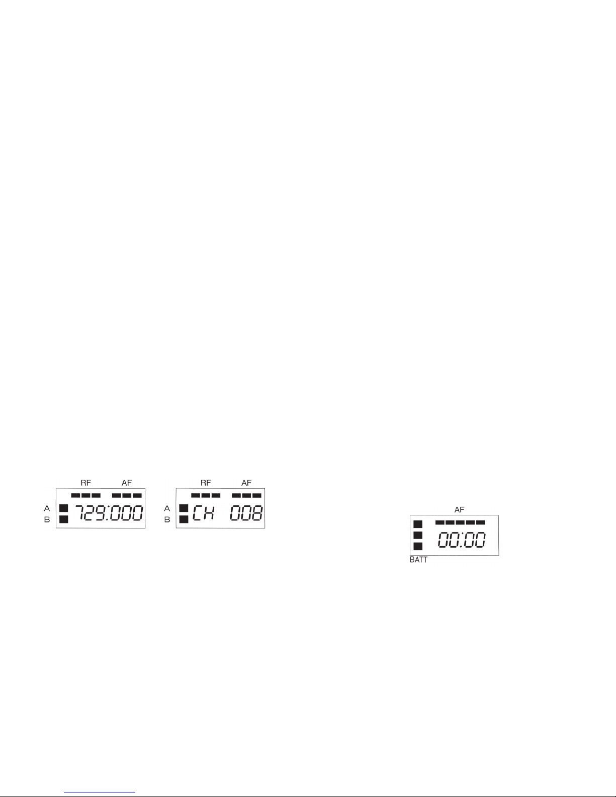
SETTING THE TRANSMITTING FREQUENCY ON THE 1000XT
Before the 1000XT can be used, it and the associated receiver have to
set to the same frequency. This can be accomplished on the 1000XT
transmitter by first setting the LCD display to one of two views - ‘Fre-
quency’ or ‘Channel’. To do this, after installing a fresh battery, turn the
1000XT to the ON position [k]. Next, using the tip of a ballpoint pen,
an unbent paper clip or something similar, press the MODE button [g]
repeatedly until one of the two screens below appears.
Using either the UP or DOWN button [h] the desired receiving fre-
quency or channel number can be set. Tapping the button steps the
frequency or channel number one at a time while pressing and holding
the button in moves through the frequencies or channel numbers rap-
idly. There are 121 different frequencies or channel numbers to chose
from. Once the desired frequency or channel has been determined
be certain to set both the transmitter and receiver to match.