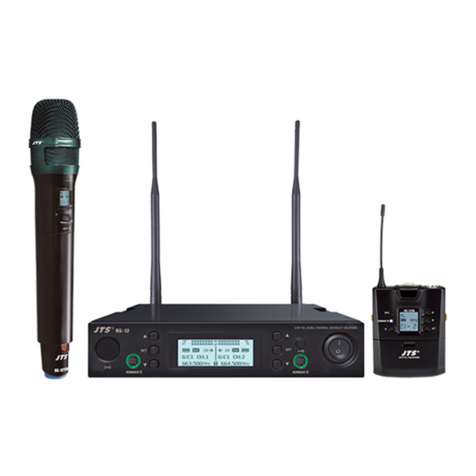
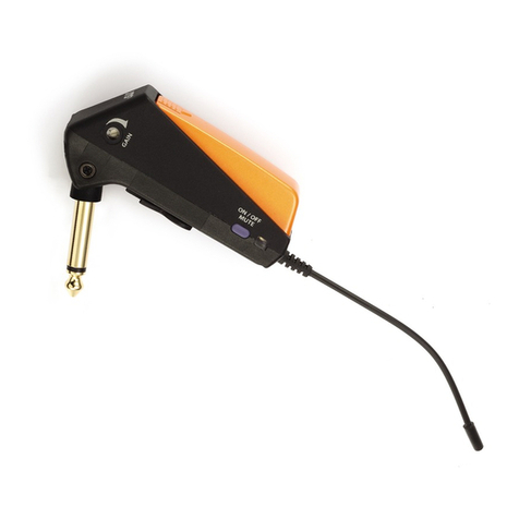
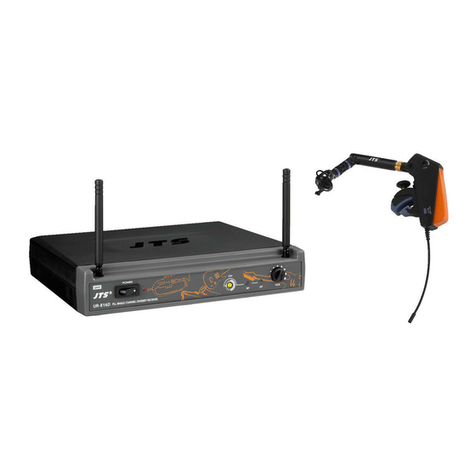
JTS UT-16G3 User manual

Smaller
Lighter
M
o
re P
o
werfu
l
GUITAR /ACCORDING /WINDS / BRASS
59508-XXX-01
PROFESSIONAL CO., LTD.
No.148,9thIndustryRoad,Ta-LiIndustrialPark,
TaichungCity,Taiwan,R.O.C.
Tel:886-4-24938803Fax:886-4-24914890
E-mail:[email protected]
www.jts.com.tw

Miniature
wireless system
instruments
music
Instruction Manual

Thank you for choosing the JTS wireless system. In order to obtain the best eciency from the
system, you are recommended to read this instruction manual carefully.

1. Important Caution
2. Features
3. Specification
3-1-1 Receiver // RU-8011D/ RU-8011DB/ RU-8012DB
3-1-2 Receiver // RU-12
3-1-3 Receiver // RU-901G3
3-2 Miniature Transmier// UT-16G3
4. Part Identification & Accessories
4-1-1 Receiver // RU-8011D
4-1-2 Receiver // RU-8011DB
4-1-3 Receiver // RU-8012DB
4-1-4 Receiver // RU-12
4-1-5 Receiver // RU-901G3
4-2 Miniature Transmier // UT-16G3
4-3 Accessorie
5. Preparing Procedures & Basic Operation
5-1 Receiver
5-2 Baery Insertion of e Transmier
5-3 Install e Transmier
6. System Operation
6-1-1 Instructions // UT-16G3
6-1-2 Instructions // RU-8011D
6-1-3 Instructions // RU-8011DB
6-1-4 Instructions // RU-8012DB
6-1-5 Instructions // RU-12
6-1-6 Instructions // RU-901G3
7. Rack Mounting
8. Recommendation
9. Important Notice
INDEX
01
01
02
02
03
04
05
06
06
08
10
12
14
16
18
14
19
20
21
23
23
26
28
31
34
40
43
44
45

01 MINIATURE MUSIC INSTRUMENT WIRELESS SYSTEM
The newly designed UT-16G3 wireless instrument microphone is equipped with JTS patented
technology with the ultrasonic wireless transmission function for users to choose
wireless synchronization parameters or set parameters manually. Advanced circuit design ensures
stable signal output and reduces noise interference. 36MHz broadband design provides more
optional frequencies and can be used with RU-901G3/RU-12/RU-8011D/RU-8011DB/RU-
8012DB and other models.
1. Important Caution
2. Features
Before connecting to the power supply, make sure that the voltage marked on the host
machine is the same as the power supply value on your outlet.
Do not place the machine in damp or hot places.
Dry your hands before operating the system.
Keep the machine away from re or heat sources.
When multiple receivers are stacked at the same time, it is advised to select frequency
points in the same group to avoid frequency interference.

02
3. Specification
3-1-1 UHF PLL single/dual-channel diversity receiver // RU-8011D(DB) / RU-8012DB
Model
Frequency Oscillation Mode Phase-locked loop (PLL)
Carrier Frequency Range 470~960 MHz
Remoset Frequency Ultrasonic
Diversity Antenna diversity
Bandwidth 36MHz
Signal/Noise Ratio >105dB(A)
Total Harmonic Distortion (Thd) <0.6%@1KHz
Receiving Sensitivity -95dBm,S/N>80dB
Image Rejection Ratio >80 dB
Frequency Response 60Hz~15KHz±2dB 50Hz~16KHz±2dB
Antenna Type 1/4λ Fixed antenna 1/2λ BNC detachable
Antenna Booster Power None DC12~15V/100mA
Function Display By LCD
Contents Of Display
Group, channel,
antenna A/B, muting
level, AF indication,
RF indication, channel
scanning, output level
attenuation, volume
indication
Group, channel, frequency, battery
level, antenna A/B, muting level, AF
indication, RF indication, channel
scanning, output level attenuation,
volume indication
Control Functions
Power, group, channel,
muting level, channel
scan (on/o), button
lock, volume, output
attenuation (XLR)
Power, group, channel, frequency,
muting level, button lock, volume,
output attenuation (XLR), channel
scan (on/o)
Audio Frequency Output Level
Ref:±22.5KHz Dev@1KHz Tone
ψ6.3 Phone Jack:-10dBV
XLR Jack:-4dBV(Line)、-24dBV(MIC)
Audio Frequency Output
Impedance 600Ω

03 MINIATURE MUSIC INSTRUMENT WIRELESS SYSTEM
3-1-2 UHF PLL dual-channel diversity receiver // RU-12
Model
Frequency Oscillation Mode Phase-locked loop (PLL)
Carrier Frequency Range 470~960 MHz
Remoset Frequency Ultrasonic
Diversity Antenna diversity
Bandwidth 36MHz
Signal/Noise Ratio >105dB(A)
Total Harmonic Distortion (Thd) <0.6%@1KHz
Receiving Sensitivity -95dBm,S/N>80dB
Image Rejection Ratio >80 dB
Frequency Response 50Hz~16KHz±2dB
Antenna Type 1/2λ BNC detachable
Antenna Booster Power DC12~15V/100mA
Function Display By LCD
Contents Of Display
Group, channel, frequency, battery level, antenna A/
B, muting level, AF indication, RF indication, channel
scanning, output level attenuation, volume indication
Control Functions
Power, group, channel, frequency, muting level, button
lock, volume, output attenuation (XLR), channel scan
(on/o)
Audio Frequency Output Level
Ref:±22.5KHz Dev@1KHz Tone
ψ6.3 Phone Jack:-10dBV
XLR Jack:-4dBV(Line)、-24dBV(MIC)
Audio Frequency Output Impedance 600Ω
Muting Noise muting and tone code locking
Output Port 2 x balanced XLR jack
2 x unbalanced ϕ6.3 jack
Power Supply 12~15V DC / 500mA
Dimension (Mm) 212.3mm (W) x 38.3mm (H) x 144mm (L)

04
3-1-3 UHF PLL single-channel True Diversity receiver // RU-901G3
Frequency Oscillation Mode Phase-locked loop (PLL)
Carrier Frequency Range 470~960 MHz
Remoset Frequency Ultrasonic
Diversity True diversity
Bandwidth 36MHz
Signal/Noise Ratio >105dB(A)
Total Harmonic Distortion (Thd) <0.6%@1KHz
Receiving Sensitivity -95dBm,S/N>80dB
Image Rejection Ratio >80 dB
Frequency Response 50Hz~18KHz±2dB
Antenna Type 1/2λ BNC detachable
Antenna Booster Power DC12~15V/100mA
Function Display By LCD
Contents Of Display
Group, channel, frequency, battery level, antenna A/B, muting
, AF indication, RF indication, channel scanning, output level
attenuation
Control Functions Power, group, channel, frequency, muting , button lock,
volume, output attenuation (XLR), channel scan (on/o)
Audio Frequency Output Level ψ6.3 Phone Jack:-10dBV
XLR Jack:-4dBV(Line)、-24dBV(MIC)
Audio Frequency Output
Impedance
600Ω
Muting Noise muting and tone code locking
Output Port 1 x balanced XLR jack
1 x unbalanced ϕ6.3 jack
Power Supply 12~15V DC / 500mA
Dimension (Mm) 212.3mm (W) x 38.3mm (H) x 144mm (L)

05 MINIATURE MUSIC INSTRUMENT WIRELESS SYSTEM
3-2 Miniature Transmitter // UT-901G3
Model UT-901G3
Frequency Oscillation
Mode PLL Synthesized Control
Carrier Frequency Range 470~960 MHz
Frequency Setting Ultrasonic / Remoset U (Receive)
RF Outputs Maximum 10mW
Stability <±10KHz@Fc
Frequency Deviation ±48KHz
Spurious Emissions <-50dBc
Function Power ON/OFF, Mute, Group,Channel, Frequency, Sensitivity, Key
Lock
Display LCD
Input Connector 3.5mm Plug (6.35mm Adapter)
Battery UM3, AA x2
Note Actual Product specifications may vary depending on model and
region

06
4. Part Identification & Accessories
4-1-1 UHF PLL single-channel diversity receiver //
Front panel
1
3
25
7
Rear panel
4
8
6
100mA
12V out
Antenna A
100mA
12V out
Antenna B
12910 11 9
1
4
2
5
3
6
7
8
Receiving antenna: xed antenna of 1/4 wave length
6.3mm phone jack: unbalanced audio output jack
3P XLR male: balanced audio output jack
DC power socket: for 12~15V DC / 300mA power supply
10
12
11
9
Power: means “ON” and means “OFF”
SET: this is for function settings. Push and hold for 2 seconds to enter the
setting mode. Push “SET” repeatedly to search for the function you wish to set.
▲/▼In the setting mode, push▲/▼to change the function parameter
In the non-setting mode: push▲/▼to adjust volume
LCD display
Lock :push and hold “Lock” for 2 seconds to lock the buttons in order to
prevent pushing any button by accident.
Remoset u : this allows user to synchronize the transmitter after modifying a
parameter. Push“ ” to synchronize the settings to the transmitter.
Remoset indicator : this shows the current pairing status. It ashes rapidly
when data is being transmitted and the ashing stops when the synchroniza-
tion is completed. However, the ashing slows down if synchronization fails
after a period of time of pairing attempt.
Ultrasonic transmission unit: it transmits digital pairing data at ultrasonic
frequency. When setting, direct the ultrasonic receiving element of the micro-
phone to the ultrasonic transmitting unit of the receivers. The eective range
is 30º on both sides with the optimized distance at 30cm.

07 MINIATURE MUSIC INSTRUMENT WIRELESS SYSTEM
15
16
18
14
17
13 : Audio signal strength
: RF signal strength
: Antenna A/B
: Group / channel
: Button lock engaged
: Receiver mute
In the non-setting mode, the LCD looks like :
13
14
15
17 18
16
/
16
LCD Display

08
Front panel Rear panel
19 20 21 221
3
25
74
8
6
Female BNC antenna port: the 50Ω BNC antenna is connected here. It
also provides a booster power of 12~15 DC / 100mA for an external
antenna booster.
6.3mm phone jack: unbalanced audio output jack
3P XLR male: balanced audio output jack
DC power socket: for 12~15V DC / 300mA power supply
19
20
21
22
1 8
~ : See page 5.
19
4-1-2 UHF PLL single-channel diversity receiver //

09 MINIATURE MUSIC INSTRUMENT WIRELESS SYSTEM
LCD Display
25
26
28
24
27
23 : Audio signal strength
: RF signal strength
: Antenna A/B
: Transmitter battery level
: Group/channel
: Volume
: Button lock
: Receiver mute
: Output attenuation
: Frequency
In the non-setting mode, the LCD looks like :
29
31
30
/
23
32
24
25
26
27 2829
30
3132

10
Front panel Rear panel
1
3
2 5
4
33 34 37 3935 3836
Female BNC antenna port: the 50Ω BNC antenna is connected here. It
also provides a booster power of 12~15 DC / 100mA for an external
antenna booster.
Male XLR (RX1): RX1 balanced audio output jack
Male XLR (RX2): RX2 balanced audio output jack
Mixing: it allows the unbalanced audio signals from RX1 and RX2 to be
mixed to RX1.
6.3mm phone jack (RX1): RX1 unbalanced audio output jack
6.3mm phone jack (RX2): RX2 unbalanced audio output jack
DC power socket: for 12~15V DC / 500mA power supply
33
34
35
36
37
38
39
1 8
~ : See page 5.
78
633
4-1-3 UHF PLL dual-channel diversity receiver //

11 MINIATURE MUSIC INSTRUMENT WIRELESS SYSTEM
42
43
45
41
44
40 : Audio signal strength
: RF signal strength
: Antenna A/B
: Transmitter battery level
: Frequency (group/channel)
: Receiver mute
: Output attenuation
: Frequency
In the non-setting mode, the LCD looks like this:
46
/
47
42
41
43
40444746
45
LCD Display

12
Front panel
4-1-4 UHF PLL dual-channel diversity receiver //
1
4
2
5
3
6
7
8
Power: means “ON” and means “OFF”
SET: this is for function settings. Push and hold for 2 seconds to enter the setting
mode. Push “SET” repeatedly to search for the function you wish to set.
▲/▼In the setting mode, push▲/▼to change the function parameter
In the non-setting mode: push▲/▼to adjust volume
LCD display
Lock :push and hold “Lock” for 2 seconds to lock the buttons in order to prevent
pushing any button by accident.
Remoset u : this allows user to synchronize the transmitter after modifying a param-
eter. Push“ ” to synchronize the settings to the transmitter.
Remoset indicator : this shows the current pairing status. It ashes rapidly when
data is being transmitted and the ashing stops when the synchronization is com-
pleted. However, the ashing slows down if synchronization fails after a period of
time of pairing attempt.
Ultrasonic transmission unit: it transmits digital pairing data at ultrasonic frequency.
When setting, direct the ultrasonic receiving element of the microphone to the ultra-
sonic transmitting unit of the receivers. The eective range is 30º on both sides with
the optimized distance at 30cm.
R -12
UHF PLL DUAL CHANNEL DIVERSIT Y RECEIVER
2
548
7
6 3
3
1
2

13 MINIATURE MUSIC INSTRUMENT WIRELESS SYSTEM
Female BNC antenna port: the 50Ω BNC antenna is connected here. It
also provides a booster power of 12~15 DC / 100mA for an external
antenna booster.
Male XLR (RX1): RX1 balanced audio output jack
Male XLR (RX2): RX2 balanced audio output jack
Mixing: it allows the unbalanced audio signals from RX1 and RX2 to be
mixed to RX1.
6.3mm phone jack (RX1): RX1 unbalanced audio output jack
6.3mm phone jack (RX2): RX2 unbalanced audio output jack
DC power socket: for 12~15V DC / 500mA power supply
9
10
11
12
13
14
15
Rear panel
DCV INPUT
12-15V/500mA
ANT.BANT.A
Freq.:Serial No.:
Mixed
ON OFF
AF OUTPUT BALANCED
RX2
AF OUTPUT BALANCED
RX1
RX2
RX1
Made In Taiwan
14
9 9
13
12 1110 15

14
4-1-5 UHF PLL single-channel diversity receiver( True Diversity ) // RU-901G3
Front panel
Power On/Off switch: Press once to turn on the power,press and hold for 2
seconds to turn of.
SET: this is for function settings. Push and hold for 2 seconds to enter the setting
mode. Push “SET” repeatedly to search for the function you wish to set.
▲/▼In the setting mode, push▲/▼to change the function parameter
In the non-setting mode: push▲/▼to adjust volume
LCD display
AF signal level
RF signal level
Volume control
Remoset Button : this allows user to synchronize the transmitter after modifying a
parameter. Push “ ” to synchronize the settings to the transmitter.
Remoset indicator : this shows the current pairing status. It ashes rapidly when
data is being transmitted and the ashing stops when the synchronization is com-
pleted. However, the ashing slows down if synchronization fails after a period of
time of pairing attempt.
Ultrasonic transmission unit: it transmits digital pairing data at ultrasonic frequen-
cy. When setting, direct the ultrasonic receiving element of the microphone to the
ultrasonic transmitting unit of the receivers. The eective range is 30º on both sides
with the optimized distance at 30cm.
Antenna
1
4
2
5
3
6
7
11
10
8
9
VOL.
MIN. MAX.
DIVERSITY RECEIVER
1
3
2
11
10
4
8
5
69
7

15 MINIATURE MUSIC INSTRUMENT WIRELESS SYSTEM
Rear panel
DC power socket: for 12~15V DC / 500mA power supply
Female BNC antenna port:
the 50Ω BNC antenna is connected here. It also
provides a booster power of 12~15 DC / 100mA for an external antenna booster.
6.3mm phone jack: unbalanced audio output jack
3P XLR male: balanced audio output jack
23
21
12
22
22 21 212320
15
16
18
14
17
13
:Antenna A/B
:Transmitter battery level
:Group/channel
:Key Lock
:Receiver mute
:Output attenuation
:Squelch level
:Frequency
In the non-setting mode, the LCD looks like :
19
20
/
13
16
1814 17
19 15 12

16
4-2 Miniature Transmitter
Power button/mute button:
On: Press the button to turn on the power and press it again for the mute mode
O: Press the power button for 2 seconds until the screen shows power o
Ultrasound receiving hole: receiving binding signals from the ultrasound trans-
mitting unit of the receiver.
LED status indicator light:
(1) Green: full battery >1V
(2) Green ash: transmitter in mute mode
(3) Red: low battery ≦1V
(4) Alternating ashing red and green: microphone in mute mode (low battery)
(5)Blue: ashing for 3 seconds indicates success in binding alignment
(6)Blue ash: error receiving data
LED display: displaying the relevant content and parameters of the transmitter
Set key: setting content parameters, including: frequency, group, channel, sensi-
tivity, digital audio code, key lock
Up/Down key: Using the “SET” key to change parameter setting
Audio plug: ψ3.5mm (6.35mm Adapter)
Battery cell: supporting AM4, AAA 1.5V*1 alkaline or rechargeable batteries
Antenna: RF antenna
Input sensitivity adjustment
UT-16GT transmitter
Battery cover (color) trim cover: green/gray
6.3GT plug: plug
516GT: accordion microphone module
508GT: microphone module for wind instruments
16GT Clip: Wind instrument clamp
516 Bracket
CLP-UT
10
2
11
3
12
4
13
14
15
16
17
5
6
7
8
9
1
Accordion/Guitar PackWinds/Brass Pack
11
14
15
17
11
13
14
15
16
Guitar/Winds Pack
11
13
14
15
SET
Guitar Pack
11
1
8
6
2
4
12
5
10
7
3
9
This manual suits for next models
6
Table of contents
Other JTS Microphone System manuals
Popular Microphone System manuals by other brands

Audio Technica
Audio Technica ATCS-60 instruction manual

FITNESS AUDIO
FITNESS AUDIO V Series operating manual

Cardin Elettronica
Cardin Elettronica RADIOSHIELD Series manual

schildknecht
schildknecht DATAEAGLE 2 Compact Series Installation and commissioning manual

audiophony
audiophony WAVE user guide

Audio Technica
Audio Technica 3000 Series Installation and operation guide