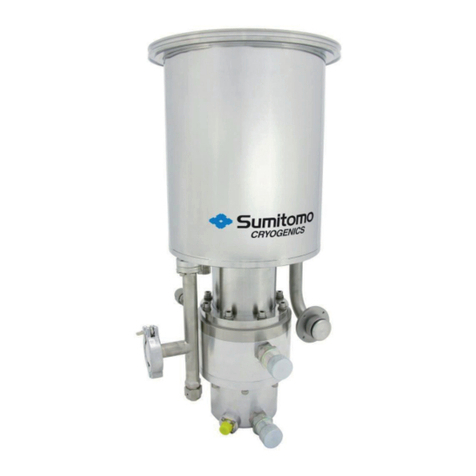
Sumitomo QT Series User manual

HMP-0567E Rev.7 (1/19)
Instruction Manual
QT Pump / QX Pump
HMP-0567E Rev.7
Read this manual before use.
Sumitomo Precision Products Co., Ltd.
< Industrial Hydraulic Systems >
Tokyo Marketing Section
Sumitomo Corporation Takebashi Bldg 4th floor,
1-2-2 Hitotsubashi, Chiyoda-ku, Tokyo 100-0003, Japan
Phone 81-(0)3-3217-2813 Fax 81-(0)3-3217-2823
Osaka Marketing Section
1-10, Fuso-cho, Amagasaki, Hyogo 660-0891 Japan
Phone 81-(0)6-6489-5946 Fax 81-(0)6-6489-5902
Rev.7 - Nov. 2020

HMP-0567E Rev.7 (2/19)
---Table of contents---
1. Before Using the Pump 3
1) Introduction
2) Checking the delivered product
3) Safety-related labeling
2. Safety Precautions 4
1) Precautions for handling the product
2) Precautions for installing/removing the product
3) Precautions for operation
4) Precautions for maintenance
3. Precautions for Handling/Using the Product 6
1-1) Explanation of model number –QT Pump
1-2) Explanation of model number –QX Pump
2) Pump installation
3) Pump and motor shafts alignment
4) Suction pressure
5) Suction filter
6) Line filter/return filter
7) Piping
8) Pressure specifications
9) Shaft speed
10) Hydraulic fluid
11) Operating environment
4. Precautions for Operation 13
1) Cleaning the interior of the tank
2) Introducing the hydraulic fluid
3) Rechecking the direction of rotation
4) Pump start-up
5) Trial run
5. Maintenance and Inspection Procedures 15
1) Cleaning the suction filter
2) Control of hydraulic fluid
3) Control of fluid temperature
6. Faults and Corrective Actions 18

HMP-0567E Rev.7 (3/19)
1. Before Using the Pump
1) Introduction
Before using the pump, please read this Operation Manual carefully and understand its contents.
a) The purpose of this manual is to ensure safe and proper use of the QT pump and QX pump by
the user.
b) Be sure to use the pump in accordance with the usage and limitations described in this
manual
c) As a result of design changes or improvements, there may be differences between the
product that you purchased and the descriptions given in this manual.
d) If you have any questions about your product or the contents of the Operation Manual, please
contact the Marketing Group, Industrial Hydraulic Department at Sumitomo Precision Products
Co., Ltd.
2) Checking the delivered product
Upon receipt of the product, please check it is the same as the product you ordered.
3) Safety-related labeling
In this Operation Manual, precautions that must be observed in order to ensure safe and proper
handling of the pump are marked with the following symbols.
: Indicates an immediate hazardous situation that, if not avoided, could result in death or
serious injury.
: Indicates a potentially hazardous situation that, if not avoided, could result in death or
serious injury.
: Indicates a potentially hazardous situation that could result in minor or medium level
injury, or in damage to property.

HMP-0567E Rev.7 (4/19)
2. Safety Precautions
: DO NOT USE THE PRODUCT IN ANY MANNER NOT DESCRIBED IN THIS MANUAL
OR OUTSIDE THE SPECIFIED LIMITS. FAILURE TO OBSERVE THIS PRECAUTION
COULD CAUSE BREAKDOWN OR DAMAGE TO THE PUMP, RESULTING IN RISK
OF PERSONAL INJURY AND/OR DAMAGE TO PROPERTY.
SUMITOMO PRECISION PRODUCTS ACCEPTS NO LIABILITY FOR USE OF THE
PRODUCT IN ANY MANNER OTHER THAN THAT DESCRIBED IN THIS MANUAL.
1) Precautions for handling the product
: CONFIRM THE MASS OF THE PRODUCT (INDICATED IN THE EXTERNAL
DIMENSIONS DIAGRAM).
IF THE MASS IS 20 KG OR MORE, DO NOT ATTEMPT TO CARRY THE PRODUCT
UNAIDED.
: UNDER NO CIRCUMSTANCES SHOULD YOU APPROACH THE PRODUCT WHILE
TRANSPORTING IT USING HOISTING EQUIPMENT.
2) Precautions for installing/removing the product
: ENSURE THAT INSTALLATION/REMOVAL IS PERFORMED BY A PERSON WITH THE
RELEVANT SPECIALIZED KNOWLEDGE.
: DO NOT GET ON TOP OF, STRIKE OR APPLY EXTERNAL FORCE TO THE PUMP.
FAILURE TO OBSERVE THIS PRECAUTION COULD RESULT IN PERSONAL INJURY
AND/OR DAMAGE TO THE PUMP.
: BEFORE INSTALLATION OR REMOVAL, BE SURE TO POWER OFF THE UNIT.
: CLEAN THE SURFACES ON WHICH THE PUMP AND FLANGES WILL BE
MOUNTED, AND CLEAN THE BOLT HOLES.
: WHEN INSTALLING THE PRODUCT, BE SURE TO USE THE SPECIFIED BOLTS, AND
TIGHTEN THEM TO THE PREDETERMINED TORQUE.
: THE PRODUCT AND HYDRAULIC FLUID MAY BE HOT IMMEDIATELY AFTER
OPERATION. PRIOR TO REMOVAL, FIRST CONFIRM THAT THE PRODUCT AND
HYDRAULIC FLUID ARE AT A SUITABLE TEMPERATURE (30°C to 40°C). NEXT,
RELEASE ANY RESIDUAL PRESSURE IN THE HYDRAULIC PIPING BEFORE
REMOVING THE PUMP.

HMP-0567E Rev.7 (5/19)
3) Precautions for operation
: BE SURE TO ATTACH A PROTECTIVE COVER TO THE ROTATING PART OF THE
PUMP IN ORDER TO ENSURE THAT IT CANNOT COME INTO CONTACT WITH
THE HUMAN BODY.
: BE SURE TO USE THE PUMP WITHIN THE RANGE OF THE SPECIFIED
OPERATING/ENVIRONMENTAL CONDITIONS, (AMBIENT TEMPERATURE,
TEMPERATURE AND VISCOSITY OF THE HYDRAULIC FLUID, ETC.). USING THE
PUMP OUTSIDE THIS RANGE COULD CAUSE MALFUNCTION OR DAMAGE, AND
MAY EVEN RESULT IN FIRE.
: DURING OPERATION, THE MAIN BODY OF THE PUMP IS AT HIGH TEMPERATURE.
DO NOT TOUCH THE PUMP WITH YOUR BARE HANDS.
4) Precautions for maintenance
: DO NOT DISASSEMBLE, REASSEMBLE OR MAKE ALTERATIONS TO THE PUMP
WITHOUT THE CONSENT OF SUMITOMO PRECISION PRODUCTS. OUR
WARRANTY DOES NOT COVER, AND WE DO NOT ACCEPT LIABILITY FOR,
DISASSEMBLY, REASSEMBLY, OR ALTERATIONS TO THE PUMP THAT ARE
PERFORMED WITHOUT OUR CONSENT.
翻訳せず:シャフトシール交換用部品セットとして、シールハウジングセットを取り扱っています。
お問い合わせください。なおOリングなどの部品単体の取り扱いは有りません。

HMP-0567E Rev.7 (6/19)
3. Precautions for Handling/Using the Product
1-1) Explanation of model number –QT Pump
a) QT Single pump
QT 33 - 16 -- A
O-ring
Tolerable suction pressure Material Material
No code
:Standard
–0.03 to +0.03 Mpa
NBR(*) NBR
H 0 to 0.2 MPa NBR NBR
V–0.03 to +0.03 MPa FKM FKM
Shaft seal
Table-3.1.1: Seal Options
(*) Shaft seal material of QX5* and QX6* is FKM as standard.
Table-3.1.2
Direction of rotation
(looking at the
shaft end)
Locations of suction
and delivery Ports
CW
CCW
Same
direction
No code
L
Opposite
direction.
F
E
Basic model
QT: QT pump
Pump size
2 to 6
Pressure indication
1: Low-pressure
2: Middle-pressure
3: High-pressure
4: Ultra-high-pressure
Nominal Displacement
Direction of rotation (looking at the shaft end)
and Locations of suction and delivery Ports.
Refer to Table-3.1.2
Seal Option
Refer to Table-3.1.1
Design No.
A: Standard
Suction
Delivery
Delivery
Suction
Special specification No.
No code: Standard
-S****: Special

HMP-0567E Rev.7 (7/19)
b) QT Double pump
QT 42 22 - 20 - 8 - - A
Table-3.1.3
Type A
Type B
Type C
Structure
Pump1 is Low-pressure
type or Medium-pressure
type
Pump1 is High-pressure
type
Pump1 and pump2 are
Medium-pressure type
and same size
Ex. Model
number
QT5143
QT5333
QT5252
Code of
locations
of suction
and
delivery
Ports
No code
F
Pump1 model number
Pump2 model number
Locations of suction and delivery Ports.
Refer to Table-3.1.3
Seal Option
Refer to Table-3.1.1
P1: Suction P2: Suction
P2: Suction P2: Delivery
P1: Suction P1: Delivery
P1: Delivery P2: Delivery
P1: Delivery
P1: Suction
P2: Delivery
P2: Suction
P2: Suction
P1: Suction
P2: Delivery
P1: Delivery
P1: Suction P2: Delivery
P1: Delivery P2: Suction
Design No.
A: Standard
Special specification No.
No code: Standard
-S****: Special

HMP-0567E Rev.7 (8/19)
1-2) Explanation of model number –QX Pump
a) QX Single pump
QX 3 3 - 16 -
b) QX Double pump
QX 42 22 -20-8 -
2) Pump installation
a) Check that the direction of motor rotation matches the direction of pump rotation.
b) Be sure to install the pump on a mounting base of high rigidity.
3) Pump and motor shafts alignment
a) Be sure to use a chain coupling or other flexible coupling to connect the pump shaft with the
motor shaft.
:The pump cannot be driven by a horizontal pulling force using pulleys or gears.
Ensure that no force is applied perpendicularly to the pump shaft.
Basic model
QX: QX pump
Pump size
2 to 6
Pressure indication
1: Low-pressure
2: Middle-pressure
3: High-pressure
H: High-pressure “H”series
Nominal Displacement
Direction of rotation (looking at the shaft end)
No code:CW (Standard)
L :CCW
Seal Option
Refer to Table-3.1.1
Special specification No.
No code: Standard
-S**** : Special
Pump1 model number
Pump2 model number
Seal Option
Refer to Table-3.1.1
Special specification No.
No code: Standard
-S**** : Special
Refer to external dimensions drawing
for locations of suction and delivery ports.

HMP-0567E Rev.7 (9/19)
b) It is recommended to machine the coupling hole such that the respective dimensions shown
in Table-3.3.1 are within the corresponding tolerances stated in the same table.
c) Do not strike the coupling with a hammer or similar tool in order to attach the coupling to the
pump shaft.
d) Before performing alignment, attach a dial gauge to the coupling, as shown in Figure-3.3.1.
Perform alignment by rotating the coupling.
: ENSURE THAT THE MISALIGNMENT BETWEEN THE SHAFTS IS 0.05 MM OR
LESS AND THAT THE ANGULAR DIFFERENCE BETWEEN THEM IS 1°OR LESS.
e) Certain operations, such as attaching a pipe or transporting/installing the unit, may cause
the misalignment to increase. After performing such operations, be sure to recheck the
misalignment.
Figure-3.3.1: Tolerance of Misalignment
Table-3.3.1: Recommended Coupling Dimensions
Pump
size
Hole dimension
Keyway dimension
Main dimensions of
coupling hole
A (Diameter)
(mm)
Tolerance
(μm)
B
(mm)
Tolerance
(μm)
C (mm)
Tolerance
(μm)
2
20
+ 28
+ 9
6
+ 40
+ 10
22.6
+ 100
0
3
25
+ 28
+ 9
8
+ 46
+ 10
28.3
+ 200
0
4
32
+ 34
+ 11
10
+ 46
+ 10
35.2
+ 200
0
5
40
+ 34
+ 11
12
+ 53
+ 10
43.2
+ 200
0
6
50
+ 40
+ 11
14
+ 53
+ 10
53.7
+ 200
0
4) Suction pressure
Ensure that suction pressure does not exceed the tolerable pressure for the shaft seal, shown in
Table-3.1.1.
Dial indicator
Allowable radial
difference = 0.05 mm max.
360° Part
Rotation
Allowable angular
difference = 1° max.

HMP-0567E Rev.7 (10/19)
5) Suction filter
a) Be sure to install a suction filter on the suction side of the pump.
b) Select a mesh size within the 100–200 range depending on the environment in which the unit
has been installed and its operating conditions.
c) Select a filter capacity that will be large enough to maintain proper operation in consideration of
increased fluid viscosity in the wintertime as well as the possibility of filter clogging.
6) Line filter/return filter
In general, it is not necessary to equip the pressure line/return line with a filter for the purpose of
protecting the pump. However, if the system is located in an unfavorable environment or has
servo valves, etc., installation of a line filter/return filter suited to the hydraulic system is
recommended.
7) Piping
a) Prior to installing pipes, please subject them to acid cleaning followed by neutralization.
b) The inner diameter of the suction pipe must be chosen such that the flow velocity inside the pipe
does not exceed 1.5 m/sec.
c) If the tank head pressure is not being applied to the suction part of the pump, ensure that the
direction of the suction pipe is as shown in one of the two illustrations in Figure-3.7.1. As a result,
even after the hydraulic fluid has drained out of the suction pipe, fluid will remain in the pump.
Figure-3.7.1: Suction Pipe Orientation According to the Mounting Posture of the Pump
d) Ensure that the piping does not cause excessive force to act on the pump.
e) It is recommended to equip the delivery pipe with an air vent valve.
GOOD GOOD NG

HMP-0567E Rev.7 (11/19)
f) It is recommended to use a rubber hose as the delivery pipe in order to reduce the vibration and
noise produced by the unit, and to prevent excessive force being exerted on the pump.
8) Pressure specifications
a) Definitions of "rated pressure" and "maximum pressure"
Rated pressure: Pressure at which the pump is able to operate on a continuous basis
Maximum pressure: Pressure at which the pump is able to operate over a period of 1/3 of
a cycle, with the maximum possible continuous operation period per
cycle being 20 seconds
In other words, after 20 seconds of operation at the maximum pressure, the pump should
operate at a pressure below the rated pressure for the remaining 40 seconds.
Table-3.8.1 QT Pump Pressure specifications
Unit: MPa (kgf/cm2)
QT*1
Low-pressure
type
QT*2
Medium-pressure
type
QT*3
High-pressure
type
QT*4
Ultra-high-press
ure type
Rated pressure
6.9 (70)
13.7 (140)
24.5 (250)
31.4 (320)
Maximum pressure
7.8 (80)
15.7 (160)
31.4 (320)
34.3 (350)
Table-3.8.2 QX Pump Pressure specifications
Unit: MPa (kgf/cm2)
QX*1
Low-pressure
type
QX*2
Medium-pressure
type
QX*3
High-pressure
type
QX*H
Ultra-high-press
ure type
Rated pressure
9.8 (100)
20.6 (210)
24.5 (250)
31.4 (320)
Maximum pressure
12.3 (125)
24.5 (250)
31.4 (320)
39.2 (400)
QX6H: 34.3 (350)
Rated / Maximum pressure and allowable shaft speed of QT2* and QX2* are different from the
above table. Please check with specification or external dimensions drawing of the pump.
b) Surge pressure
Ensure that pressure, including surge pressure, does not exceed the maximum pressure.

HMP-0567E Rev.7 (12/19)
9) Shaft speed
If the operating shaft speed is within the range shown in Table-3.9.1, the pump can be operated
continuously.
Table-3.9.1: Rated shaft speed ranges
Rated shaft speed
1000—1800 min-1
Allowable shaft speed of QT2* and QX2* are different from the above table. Please check with
specification or external dimensions drawing of the pump.
10) Hydraulic fluid
a) Fluid type
Use a hydraulic fluid with an ISO VG (Viscosity Grade) of 46 to 68 (equivalent to a viscosity
index of 90 or more).
If the operating pressure exceeds 6.9 MPa, use an anti-wear hydraulic fluid.
If a phosphate ester type hydraulic fluid is used, the seal option must be selected to "V." (Refer
to Section 3.1.)
Please contact us if considering the use of any hydraulic fluid not listed above, or the use
of a fire-resistant fluid (excluding w/o emulsion type and fatty acid ester based hydraulic
fluids).
b) Viscosity
If the operating pressure is greater than 6.9 MPa, use a hydraulic fluid with a viscosity of 20 to
500 mm2/s.
If the operating pressure is 6.9 MPa or less, a hydraulic fluid with a viscosity of 2 to 500 mm2/s
may be used.
c) Fluid temperature
Ensure that the temperature of the hydraulic fluid during operation is within the 0 to 60°C range.
d) Degree of contamination
Use a clean hydraulic fluid (ISO Code 22/20/17 or lower).

HMP-0567E Rev.7 (13/19)
11) Operating environment
Do not use the pump in an unusual (e.g., hot or humid) atmosphere. Be sure to use the pump
under the following operating conditions:
Ambient temperature: −15 to 50°C
RH (Relative humidity): 0 to 95%
It is assumed, as a standard, that the pump will be used indoors. Please contact us regarding
use in an unusual environment.
: AVOID USE IN AN EXPLOSIVE ATMOSPHERE. SUCH USE COULD CAUSE A FIRE
OR ACCIDENT RESULTING IN INJURY OR DEATH.
4. Precautions for Operation
1) Cleaning the interior of the tank
Clean the interior of the tank prior to introducing hydraulic fluid into it.
2) Introducing the hydraulic fluid
a) Introduce a sufficient volume of hydraulic fluid, also taking the internal volume of the actuator
into account.
b) Bubbles may be formed if a motor-driven pump etc. is used to feed in hydraulic fluid. If this
occurs, start operation of the pump after the bubbles have disappeared.
3) Rechecking the direction of rotation
Recheck that the direction of rotation of the motor matches the direction of rotation of the pump.
4) Pump start-up
: ON-LOAD STARTUP IS NOT SUPPORTED. ON-LOAD STARTUP WILL CAUSE
DAMAGE TO THE INTERNAL PARTS OF THE PUMP.
In the following cases, the suction pipe must be bled of air.
- When the unit is being operated for the first time;
- After replacing the hydraulic fluid;
- After cleaning the suction filter.
First, confirming that the tank is filled with hydraulic fluid and open the relief valve in the delivery
line.
Then we recommend the following steps.

HMP-0567E Rev.7 (14/19)
a) If the tank head pressure is not being applied to the suction part of the pump.
- After removing the pipe flange, introduce hydraulic fluid into the pump whilst rotating
the pump shaft so that the pump fills with hydraulic fluid.
- Reconnect the pipe flange.
- Perform inching startup.
- Carry out unloaded operation at the maximum operating RPM for at least 5 minutes
and perform final confirmation that the pipe has been bled of air.
b) If the tank head pressure is being applied to the suction part of the pump.
- Partially open the pump delivery line, and then rotate the pump by hand to confirm that
hydraulic fluid emerges from the opened section.
- Close the opened section.
- Perform inching startup.
- Carry out unloaded operation at the maximum operating RPM for at least 5 minutes
and perform final confirmation that the pipe has been bled of air.
The following methods are recommended for inching startup.
- Perform intermittent operation of the pump 5 to 10 times with no load applied.
- When performing this intermittent operation, ensure that the duration of motor operation is 0.5
to 1 sec.
- If the pump is variable speed driven, adjust the RPM to 600 rpm or greater.
Repetition of this inching process will cause the gradual disappearance of the noise created by
entry of air. If this noise does not disappear, check for entry of air into the suction pipe etc.
5) Trial run
After completing pump startup, perform a trial run whilst paying attention to the following:
a) Increase the hydraulic circuit pressure gradually. The following pressurizing pattern is
recommended.
- Operate at the pressure for 50/ 70/ 90/ 100 % against the operating pressure: 100% for 5
minutes or more.
- Implement a short time on-load / unload operation after increasing the pressure. See to
Figure-4.5.1.

HMP-0567E Rev.7 (15/19)
Figure-4.5.1 pressurizing pattern
b) When pressurizing the hydraulic circuit, confirm that there is no noise made by entry of air.
・If the pump is being used with a large-sized actuator, air may return to the tank via the
actuator during the trial run. If this occurs, bleed the piping and actuator of air at the
minimum allowable pressure.
・If a large volume of air has returned to the tank, wait for the bubbles to disappear before
performing the trial run.
c) For a unit that includes a cooler, a trial run may be performed without water piping.
In this case, care should be exercised, since the fluid temperature will increase rapidly. Ensure
that the fluid temperature and viscosity during operation are within the specified ranges.
5. Maintenance and Inspection Procedures
Items for inspection, intervals between inspections and acceptance criteria are shown in
Table-5.3.1.
1) Cleaning the suction filter
Inspect the suction filter if the sound produced by pump operation has changed from that produced
when the pump was installed.
The state of filter contamination varies depending on the hydraulic system and/or the surrounding
environment, etc.
5 min.
1 sec.
2 sec.
3 sec.
5 sec.
30 sec.
*Same time as pressure 50%
Time
50%
70%
90%
100%
Pressure

HMP-0567E Rev.7 (16/19)
In general, a filter inspection should be conducted every one to three months.
If a suction filter with a clogging indicator is used, be sure to clean or replace the filter element
within the period in which the indicator is yellow.
Startup after a filter inspection should be performed in accordance with the instructions given in
Section 4.4.
2) Control of hydraulic fluid
Deterioration/contamination of hydraulic fluid occurs due to accumulation of dirt which has passed
through the filter, sludge produced from deteriorated hydraulic fluid, and entry of external water
into the hydraulic circuit, etc.
Contamination of the hydraulic fluid varies depending on the hydraulic system and/or the
surrounding environment, but it is recommended to inspect during the period shown in Table-5.3.1.
3) Control of fluid temperature
It is necessary to control the hydraulic fluid temperature (in the tank) such that the hydraulic fluid
viscosity is within the specified range.
Care needs to be taken if the atmospheric temperature is high, since a rapid increase in hydraulic
fluid temperature may occur due to deteriorated performance of the cooling tower.
Table-5.3.1: Items for Inspection, Intervals between Inspection, and Acceptance Criteria
Item
Method
Interval
Acceptance criteria
Remarks
A) Fluid
temperature
Thermometer
Continuous
monitoring
Fluid temperature at
which the fluid viscosity is
200 mm2/s (60ºC or less
for ISO VG 46 hydraulic
fluid)
Note: When used at a
pressure of 6.9 MPa
Shortage of cooling
water
Deteriorated cooler
performance
Valve sticking, etc.
B) Hydraulic
fluid
1) Degree of
contamination
2) Viscosity
3) Deterioration
4) Moisture
content
Analysis
3 to 4 months
6 months
6 months
3 to 4 months
ISO Code 22/20/17 or
lower
As stipulated in the
control standard of
the hydraulic fluid
manufacturer
If substantial
contamination or
discoloration is visible,
replacement is
required.

HMP-0567E Rev.7 (17/19)
C) Suction filter
Overhaul
inspection
1 to 3 months
For a suction filter with an
indicator, cleaning or
replacement should be
performed within the
period in which the
indicator is yellow.
If the environment
surrounding the
system is unfavorable,
the interval between
inspections should be
shortened.
If the suction filter
becomes clogged, the
volume of sound
produced by pump
operation increases.
D) Status of
pump operation
D-1) Sound of
pump
Auditory
inspection
1 month
The volume of sound
produced by the pump is
no larger than when the
pump was operated for
the first time.
Attention should be
paid to looseness of
the suction pipe due to
vibration, and entry of
air due to abrasion of
the pump shaft seal,
etc.
D-2) Pump
main body
temperature
Thermometer
1 month
≤Fluid temperature
during suction +15°C
D-3) Pump
vibration
Tactile check
1 month
No abnormal vibrations
are felt.
A check should also be
performed on the
pump delivery pipe.
Abrasion of the
coupling.
D-4) Pump
displacement
Actuator speed
1 to 3 months
No reduction in actuator
speed has occurred.

HMP-0567E Rev.7 (18/19)
6. Faults and Corrective Actions
In the event of the problems listed below, stop the motor immediately and perform an inspection,
as described in Table-6.1.
(A) No hydraulic fluid is discharged.
(B) No pressure increase occurs.
(C) The volume of noise is large.
(D) An abnormal increase in fluid temperature occurs.
Table-6.1Typical Causes of Faults in Hydraulic System and Corrective Actions
Fault
Cause
Action
(A) No hydraulic
fluid is discharged
The direction of rotation of the
motor is incorrect.
Correct the direction. (Refer to Section 3.1.)
Low fluid level
Refuel the pump so that the fluid level in the oil gauge
aligns with the oil gauge upper limit line.
The suction pipe or suction
filter is clogged.
Clean the suction pipe and suction filter.
If the suction pipe/filter is heavily clogged, replace the
hydraulic fluid.
Air is drawn in from the suction
pipe.
Using an oil gauge, confirm that there is a suitable
volume of fluid. Repair the gasket at the pipe joint.
Tighten the threaded joint of the suction pipe to an
adequate degree.
The pump shaft does not
rotate.
Inspect the motor and coupling.
Check that the pump shaft can be rotated easily using
a spanner etc. If it does not rotate, the interior of the
pump may be damaged.
(B) No pressure
increase occurs.
The pressure setting of the
relief valve is too low.
Adjust the pressure to the correct setting using an
accurately calibrated pressure gauge.
The relief valve is stuck.
After disassembling and cleaning the pressure
regulating section, adjust or replace parts as required.
There is a large amount of
leakage in the hydraulic circuit
system (leakage from the
cylinder/valve).
Inspect the relevant parts by individually blocking each
section of the hydraulic circuit, and adjust or replace
parts as required.
The pump is operating at an
RPM below the minimum rated
RPM.
Increase the RPM.
(Refer to Section 3.9.)

HMP-0567E Rev.7 (19/19)
(C) The volume of
noise is large.
The hydraulic fluid in the tank
looks cloudy due to the
presence of bubbles.
Check if air is being drawn in from the suction pipe.
The suction pipe/suction filter
is partially clogged.
Clean the suction pipe and suction filter.
The fluid temperature is too
low.
Viscosity is too high.
Decrease the fluid temperature to a suitable value.
Exercise care when selecting the fluid to be used.
Abrasion of the coupling/
incorrect alignment between
motor and pump shafts
Reapply grease.
Check/adjust alignment.
The pressure is too high
Reset pressure.
If none of the aforementioned
problems were found, the
pump may be faulty.
Please contact us.
(D) An abnormal
increase in fluid
temperature
occurs
There is no flow of cooling
water in the cooler.
Restore the flow of cooling water. Check that the valve
opens and closes correctly.
The cooling pipe of the cooler
is contaminated.
Clean the cooling pipe.
The temperature of the pump
main body is 25°C or more
higher than that of the fluid
during suction.
Replace the pump, as a pump fault may have caused
an abnormal increase in internal leakage.
This manual suits for next models
4
Table of contents
Other Sumitomo Water Pump manuals
Popular Water Pump manuals by other brands

esotec
esotec Water Splash 2/175 Usage instructions

Ceco
Ceco Sethco 2500 Series Operation manual

ITT
ITT FLOJET G57C Series Installation & operation

Dover
Dover Ebsray R75 Installation, operation & maintenance instructions

SkyLink
SkyLink SA80 Operation and maintenance manual

Makita
Makita MP001G instruction manual

Maruyama
Maruyama MP2531CE-1 operating manual

Harbor Freight Tools
Harbor Freight Tools Pacific Hydrostar 68422 Owner's manual & safety instructions

Circor
Circor IMO G12D S-137 Series Product service manual

hillvert
hillvert HT-FP-18W-900 user manual

Zenit
Zenit S-E-O-I-N-P-X-B-Y First installation manual

Sandpiper
Sandpiper SB1-A Service and operating manual