Summit TX25H User manual

OPERATOR
MANUAL
TX25H
TM
www.summittractors.com

Summit Tractors LLC
3379 Peachtree Road NE Suite 555
Atlanta GA 30326
OPERATOR’S MANUAL
Part Code: 300339271A
Revision 00, English
Summit TX25 Hydrostatic Tractor
Publication No: SMMT/AUG21/06

On behalf of the enre Summit Tractors team, we thank you for the confidence that you have in the Summit
Tractors™ brand and our products, the retail store where you made your purchase, and our family of U.S. and
internaonal tractor, aachments, res & wheels, and accessories manufacturing partners.
We realize that you have many choices when it comes to purchasing compact ulity tractor equipment, and
we endeavor to exceed your expectaons for the overall value, quality and producvity of the equipment, and
through our customer and equipment service network.
Doug Rehor Daniel Patterson
Sincerely,
Founder & CEO Chief Operating Officer
If you haven’t already done so, we invite you to download the Summit Tractors Connect™ iOS or Android app,
where you will find an abundance of resources, all designed to help you and your family get the most out of
your tractor, properly maintain it, and to help fulfill your dreams for the family homestead.
To properly maintain your equipment, you will find very useful informaon related to roune checks and
periodic maintenance in Chapter 5, MAINTENANCE. If you want to perform your own periodic maintenance,
we will assist by providing access to the right parts and procedures as found through the Summit Tractors
Connect™ app. If you’d like to have one of our Summit Tractors Service Partners handle tractor maintenance
for you, use the app to find the service locaon nearest you.
Again, we thank you, and welcome you to the family of Summit Tractors™ owners. We will always do our best
to support you throughout many years of producve and trouble-free use of your equipment.
Before using your tractor, we highly recommend that you and any other person that will use your tractor read
this operator’s manual thoroughly, with a parcular focus on the SAFETY related informaon covered in
Chapter 2, WARRANTY & SAFETY.
This publication has been written in compliance with International Standard ISO 3600 'Guide for information,
contents and presentation of operation and maintenance manuals supplied with tractors and machinery for
agricultural and forestry use.
Dear Summit Tractor Owner,
Welcome to the Summit Tractor’s Family


DESCRIPTION
CHAPTER 1: INTRODUCTION & IDENTIFICATION
Engine Serial Number.......................................................................................................................................10-8
Statutory Plate...................................................................................................................................................10-8
Universal Symbols ............................................................................................................................................10-9
Guidelines about Safety Sign............................................................................................................................20-5
CHAPTER 2: WARRANTY & SAFETY
Warranty Guidelines...................................................................................................................................... 20-1-4
Using This Operator Manual .............................................................................................................................10-7
Chassis Serial Number .....................................................................................................................................10-8
ROPS Certificate Plate......................................................................................................................................10-8
Left Turn Indicator .............................................................................................................................................30-3
Parking Brake Indicator.....................................................................................................................................30-3
Right Turn Indicator...........................................................................................................................................30-4
High Beam Indicator..........................................................................................................................................30-4
Cold Start Indication..........................................................................................................................................30-4
Air Cleaner Clogging Indicator .......................................................................................................................... 30-3
Engine Oil Pressure Indicator ...........................................................................................................................30-5
Instrument Panel...............................................................................................................................................30-2
Battery Charge Indicator ...................................................................................................................................30-3
Safety Labels Location.................................................................................................................................20-6-10
Safety: Prepare For Safe Operation................................................................................................................20-11
Safety While Operating Loader Attachments...................................................................................................20-24
Safety From Lightning Strike...........................................................................................................................20-25
Safety Labels.....................................................................................................................................................20-5
Safety Notes...............................................................................................................................................20-12-25
Noise & Vibration Levels.................................................................................................................................20-26
CHAPTER 3: INSTRUMENTS & CONTROLS
Tractor Controls ................................................................................................................................................30-1
Operator’s Seat...............................................................................................................................................30-12
Operator Presence Control (OPC)....................................................................................................................40-1
Seven Pin Socket............................................................................................................................................30-13
CHAPTER 4: OPERATION
Tractor Lights...................................................................................................................................................30-11
Battery.............................................................................................................................................................30-13
Boarding the Tractor..........................................................................................................................................40-1
Fuse Box.........................................................................................................................................................30-10
Cruise Control Switch......................................................................................................................................30-10
Temperature Gauge ..........................................................................................................................................30-5
Dashboard Controls ..........................................................................................................................................30-8
Cruise Control ...................................................................................................................................................30-7
PTO On/Off Switch .........................................................................................................................................30-10
PTO Monitor Lamp............................................................................................................................................30-6
Trailer Turn Indicator .........................................................................................................................................30-6
Engine RPM (Revolution Per Minute) Meter and Hour Meter...........................................................................30-6
Work Lamp Indicator.........................................................................................................................................30-7
Fuel Gauge .......................................................................................................................................................30-7
TABLE OF CONTENTS

DESCRIPTION
PTO ON-OFF Switch ........................................................................................................................................40-6
PTO...................................................................................................................................................................40-7
Power Steering................................................................................................................................................40-10
Transport Lock (Response Valve)....................................................................................................................40-10
2WD / 4WD’ Lever ............................................................................................................................................40-5
Differential Lock ................................................................................................................................................40-6
Hi-Low Lever....................................................................................................................................................40-11
Hand Throttle Lever ..........................................................................................................................................40-6
Hydraulic Coupling Devices.............................................................................................................................40-10
Under Hood Muffler...........................................................................................................................................40-4
Cruise Control ...................................................................................................................................................4 0-5
Opening and closing the Hood..........................................................................................................................40-4
Speed Control Pedal.........................................................................................................................................4 0-4
Leaving the Tractor ...........................................................................................................................................40-1
Engine...............................................................................................................................................................40-1
Breaking in ........................................................................................................................................................40-3
Starting the Engine ...........................................................................................................................................40-1
Turning off the Engine.......................................................................................................................................40-3
CHAPTER 5: MAINTENANCE
Gear Speed Chart...........................................................................................................................................40-12
Check Wheel Nut Bolt, Tread Settings............................................................................................................40-12
Maintenance Schedule .....................................................................................................................................50-1
Wheels and Tires (Tire Inflation Pressure & Load Carrying Capacity)............................................................40-12
Service Brakes ................................................................................................................................................40-11
Three Point Linkage........................................................................................................................................40-14
Roll Over Protection Structure (ROPS) ..........................................................................................................40-16
Parking Brake .................................................................................................................................................40-11
Fuel Tank Filling ................................................................................................................................................50-3
Radiator Fins Cleaning......................................................................................................................................50-6
Air Bleeding of Fuel System..............................................................................................................................50-4
Checking Engine Oil Level................................................................................................................................50-5
Checking Coolant Level in Radiator..................................................................................................................50-4
Radiator Draining & Flushing (When cold)........................................................................................................50-6
Radiator.............................................................................................................................................................50-4
Replacement of Oil Filter & Engine Oil .............................................................................................................50-5
Replacement of Fuel Filter................................................................................................................................50-4
Radiator Cap.....................................................................................................................................................50-6
Inspection of Hoses...........................................................................................................................................50-6
Air Cleaner Maintenance ..................................................................................................................................50-7
Oil Changes in 4WD Front Axle ........................................................................................................................ 50-8
Transmission and Hydraulic Oil Change...........................................................................................................50-8
Transmission Oil grades ...................................................................................................................................50-9
Hydraulic Filter Replacement ..........................................................................................................................50-10
Foot Brake Pedals.............................................................................................................................................50-8
Steering Cylinder Knuckle Joints ......................................................................................................................50-8
TABLE OF CONTENTS

DESCRIPTION
Starter Motor .....................................................................................................................................................50-14
Alternator...........................................................................................................................................................50-14
Checking V-belt .................................................................................................................................................50-14
General Maintenance of Electrical System .......................................................................................................50-12
Cleaning of Suction Strainer .............................................................................................................................50-11
Battery and its Maintenance .............................................................................................................................50-13
Fuses in Fuse Box ............................................................................................................................................50-13
Long Storage Period .........................................................................................................................................50-13
CHAPTER 7: DO’S AND DON'TS
Greasing Points.................................................................................................................................................50-15
Service Record....................................................................................................................................................80-3
Jack Up the Tractor - Lifting Points ...................................................................................................................50-16
Adjusting V-belt tension ....................................................................................................................................50-14
CHAPTER 6: TECHNICAL SPECIFICATIONS
Technical Specifications ......................................................................................................................................60-1
CHAPTER 8: TROUBLESHOOTING, SERVICE RECORD & ALPHABETICAL INDEX
Do’s & Don’ts....................................................................................................................................................70-1-3
Troubleshooting................................................................................................................................................80-1-2
Alphabetical Index...............................................................................................................................................80-4
Oil and Lubrication Chart ..................................................................................................................................50-16
TABLE OF CONTENTS

INTRODUCTION & IDENTIFICATION
10-7
This manual is an important part of your tractor and it should be kept with the tractor it at all times.
Reading this manual will help you and others avoid personal injury or damage to the tractor. Information provided in
this manual will help you to use the tractor in safest and effective way.
The tractor shown in this manual may differ slightly from your tractor, but will be similar enough to help you
understand our instructions.
Using This Operator Manual
Throughout this manual, the use of terms left side, right side, front side and rear side must be understood, to avoid
any confusion when following these instructions. The left and right means left and right sides of the tractor when
facing in the direction of forward travel, reference to the front indicates the radiator end of the tractor, while the rear,
indicates the draw bar end.
Always specify the tractor chassis and engine serial numbers when you need replacement parts. This will facilitate
correct & faster delivery of required parts from the authorized servicing dealer. For easy reference, we suggest you
to record these numbers in the space provided in the ‘ownership and tractor details’ page before this chapter.
If you have an attachment, use the safety and operating information in the attachment operator’s manual along with
the tractor operator’s manual to operate the attachment safely and correctly.
Right
Left
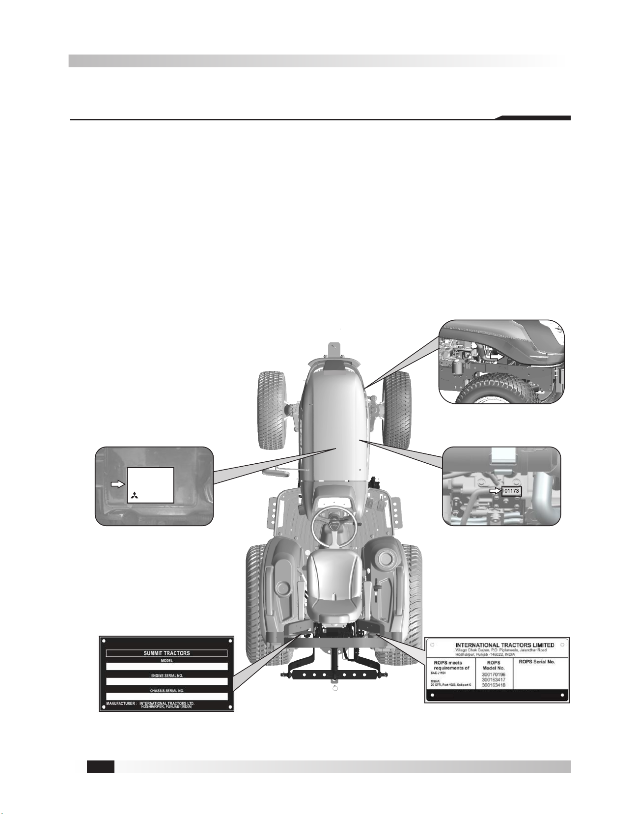
Engine Serial Number (B): The engine serial number is stamped on the upper side of the fuel injection pump
installation part located in the right side of cylinder block. For easy reference, engine serial number is also
mentioned on valve cover of the engine (see fig. B).
ROPS Certificate Plate (D) - Optional: ROPS certificate plate is riveted on ROPS. Information about ROPS
serial number and tractor model is engraved on ROPS plate. For countries under EEC, ROPS certificate plate
is used as shown in fig. D.
Chassis Serial Number (A): Chassis number is punched on right side of front axle bracket of the tractor (see
fig. A). Should you find the number difficult to read, you will also find it on the statutory plate.
Statutory Plate (C): Chassis number is also engraved on statutory plate. Statutory plate is located on left hand
side fender (fig. C).
Fig. A: Chassis Serial Number
Fig. C: Statutory Plate
Fig. B: Engine Serial Number
(Punch)
Fig. D: ROPS Certificate Plate
Model :
MITSUBISHI
DIESEL ENGINE
Serial No :
Manufacturing Date :
MHIL DIESEL ENGINE PVT. LTD.
Application : Variable Speed
MADE IN INDIA
Fig. B: Engine Serial Number
(Sticker)
INTRODUCTION & IDENTIFICATION
10-8
SUMMIT TX25
VEHICLE MODEL NUMBER- SUMMIT TX25
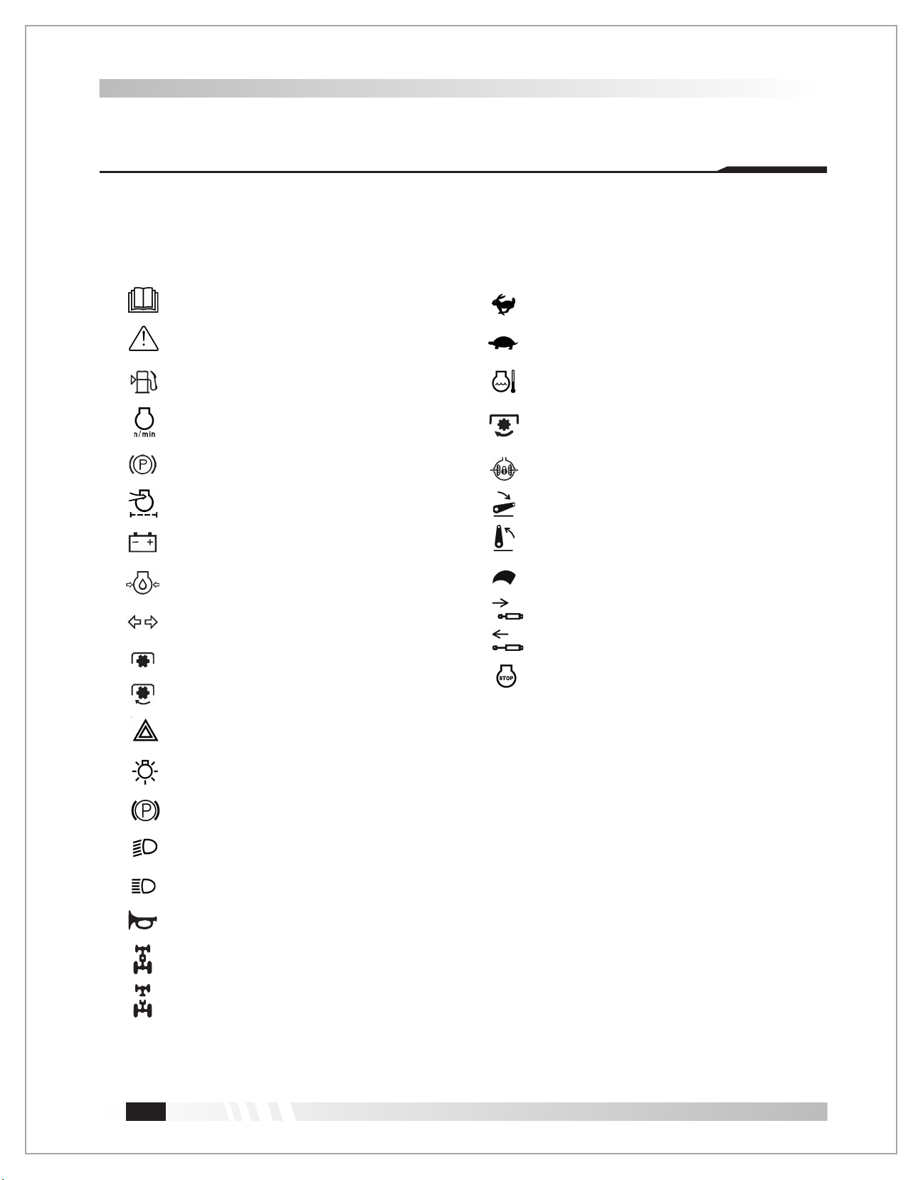
10-9
As a guide to the operation of your tractor, various universal symbols have been utilized on the instruments,
controls and other places on tractor. The symbols are shown below with an indication of their meaning.
Safety Alert Symbol
Fuel Level
Engine Rotational Speed
Parking Brake
Air Cleaner Clogging Sensor
Battery Charging Condition
Engine Oil-Pressure
Turn Signal
Power Take-Off Clutch Control-Off Position
Power Take-Off Clutch Control-On Position
Hazard Warning Lights
Master Lighting Switch
Headlight-Low Beam
Headlight-High Beam
Audible Warning Device
Four-Wheel Drive-On
Four-Wheel Drive-Off
Engine Coolant-Temperature
Slow
Fast
Parking Brake Indication
PTO 540
540
Read Operator's Manual
Engine Speed Control
Differential Lock
Hydraulic Control-Lowered Position
Hydraulic Control-Raised Position
Remote Cylinder-Retract
Remote Cylinder-Extend
Engine Stop
Universal Symbols
INTRODUCTION & IDENTIFICATION
Other manuals for TX25H
1
Table of contents


