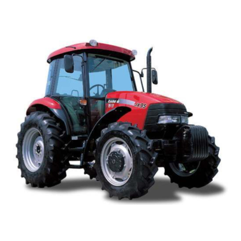
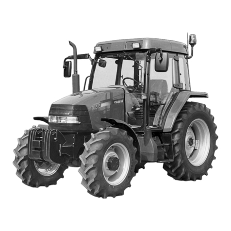
Case 385 Diesel Install guide

SHOPMANUAL
CASE/INTERNATIONAL
MODELS
385—485—585—685—885
Engineserialnumberisstampedonright sideof
enginecrankcaseonallmodels.Tractormodeland
serialnumberarestampedona plateattachedto
right sideoffrontaxlesupport.Transmissionserial
numberisstampedona plateattachedtotheright
rearsideofrearmainframe.Modelandserialnum-
berplateforfrontdriveaxleislocatedonleftrear
ofaxlehousing.
INDEX(ByStarlingParagraph)
BRAKES
At^ustment
Bleed
MasterCylinders
R&RandOverhaul
CLUTCH,ENGINE
Adjustment
Cylinders
R&RandOverhaul
CAB
RemoveandReinstall...
COOLINGSYSTEM
Pan
Radiator
WaterPump
DIESELFXTELSYSTEM
EtherStartingAid
FiltersandBleeding
IiyectionPump
Nozzles
385
Diesel
121
122
124
123
97
101
69
68
71
67
60
61
64
485
Die8el
121
122
124
123
97
101
69
68
71
67
60
61
64
585
Diesel
121
122
124
123
97,98
99
101
145
69
68
71
67
60
61
64
685
Diesel
121
122
124
123
97,98
99
101
145
69
68
71
67
60
61
64
885
Diesel
121
122
124
123
97,98
99
101
145
69
68
71
67
60
61
64
www.maskinisten.net

INDEX(CONT.)
DIFFERENTIALLOCK
R&RandOverhaul
ELECTRICALSYSTEM
Alternator
Batteries
ChargingSystem
StartingMotor
ENGINE
Assembly,R&R
Balancer
CamFollowers
CamshaftandBearings....
ConnectingRodsand
Bearings
CrankshaftandMain
Bearings
CrankshaftOilSeals
CybnderHead
Flywheel
IryectionTiming
NozzleSleeves
OilPan
OilPump
PistonPins
PistonRemoval
Pistons,SleevesandRings.
RockerArms
TimingGearCover
TimingGears
ValvesandSeats
ValveGuidesandSprings. .
FENDERS,
FUELTANKAND
PLATFORM
RemoveandReinstall
FINALDRIVE
Assemblies,R&R
PlanetaryCarrier
RearAxles
FRONTSYSTEM(Two-Wheel
Drive)
AxleMainMember
FrontSupport
Spindles
TieRodsandTbe-In
WheelBearings
385
Diesel
116
78
72
74
85,91
34
39
46
51
52
53,54
35
55
61
36
59
58
50
48
49
40
41
42
37
38
144
118
119
120
4,5
7
2,3
6
1
485
Diesel
116
78
72
74
85,91
34
39
46
51
52
53,54
35
55
61
36
59
58
50
48
49
40
41
42
37
38
144
118
119
120
6
1
585
Diesel
116
78
72
74
85,91
34
56
39
46
51
52
53,54
35
55
61
36
59
58
50
48
40
40
41
42
37
38
144
118
119
120
4,5
7
2,3
6
1
685
Diesel
116
78
72
74
85,91
34
56
39
46
51
52
53,54
35
55
61
36
59
58
50
48
49
40
41
42
37
38
144
118
119
120
4,5
7
2,3
6
1
885
Diesel
116
78
72
74
85,91
34
56
39
46
51
52
53,54
35
55
61
36
59
58
50
48
49
40
41
42
37
38
144
118
119
120
4,5
7
2,3
6
1
www.maskinisten.net

INDEX(CONT.)
FRONT-WHEELDRIVE
AxleAssembly,R&R
DifferentialandBevel
DriveGears
FrontDriveShaft
FrontSupport
SwivelHousingandAxle
Shaft
TieRodsandTbe-In
TransferGearbox
WheelHubandPlanetary
,
385
Diesel
8
12
16
11
19
17
10
HYDRAUUCSYSTEM
AuxiliaryControlValves...143
Filter,FluidandPump142
UftCylinderandValve...139
RaiseRateValve140
Rockshaft141
R&RLiftUnit. 137
IbstandAdjust129
TroubleShooting128
UnloadingandFlow
ControlValve136
MAINDRIVEBEVELGEARS
ANDDIFFERENTIAL
R&RandOverhaul115
PARKBRAKE117
POWERSTEERINGSYSTEM
Cylinder30,31,32
FlowDivider28
FlowandPressureTests...22
LubricationandBleeding.. 21
OilCooler33
Operation20
Pump26
SteeringHandPump29
POWERTAKE-OFF
Clutch,ShaftsandGears..127
LinkageAdjustment125
OperatingPressure126
TRANSMISSION,FORWARD-
REVERSE
Operation105
Regulator(Control)Valve..107
R&RandOverhaul109
TroubleShooting106
485
Diesel
8
12
16
11
19
17
10
143
142
139
140
141
137
129
128
136
585
Diesel
8
12
16
9
11
19
17,18
10
143
142
139
140
141
137,138
129
128
685
Diesel
8
12
16
9
11
19
17,18
10
143
142
139
140
141
137,138
129
128
885
Diesel
8
12
16
9
11
19
17,18
10
143
142
139
140
141
137,138
129
128
136136136
115
117
30,31,32
28
22
21
33
20
26
29
127
125
126
105
107
109
106
115
117
30,31,32
28
22
21
33
20
26
29
127
125
126
105
107
109
106
115
117
30,31,32
28
22
21
33
20
26
29
127
125
126
105
107
109
106
115
117
30,31,32
28
22
21
33
20
26
29
127
125
126
•
•
•
•
• •
•
•
•
www.maskinisten.net

INDEX(CONT.)
385
Diesel
TRANSMISSION,TWOSPEED
POWERSHIFT
Operation102
Regulator(Control)Valve. . 103
R&RandOverhaul104
TRANSMISSION,RANGE
R&RandOverhaul111,112,113
TransferLubePump114
TRANSMISSION,SYNCHRO-
MESH(SPEED)
R&RandOverhaul
485
Diesel
102
103
104
111,112,113
114
585
Diesel
102
103
104
111,113
114
685
Diesel
102
103
104
111,113
114
885
Diesel
102
103
104
111,113
114
110nononono
DUALDIMENSIONS
ThisservicemanuaiprovidesspecificationsinboththeU.S.CustomaryandMetric(Si)systemofmeasurements.
Thefirstspecificationisgiveninthemeasuringsystemusedduringmanufacture,whiiethesecondspecification
(giveninparenthesis)istheconvertedmeasurement.(Forinstance,a specificationof**0.011inch(0.279mm)"would
indicatethattheequipmentwasmanufacturedusingtheU.S.systemofmeasurementandthemetricequivalent
of0.011inchis
0.279
mm.
CONDENSEDSERVICEDATA
385485585
DieselDieselDiesel
GENERAL
EngineMakeCase/International
EngineModelD-155D-179D-206
NumberofCylinders3 3 4
Bore
3.875
in.
3.875
in.
3.875
in.
(98.4mm)(98.4mm)(98.4mm)
Stroke4.37in.5.06in.4.37in.
(111.1mm)(128.5mm)(111.1mm)
Displacement155cu.in.179cu.in.206cu.in.
(2.54L)(2.93L)(3.38L)
MainBearings,
Numberof4 4 5
CylinderSleevesWetWetWet
ForwardSpeeds,
Numberof8(1)8(1)8(1)
Alternator/StarterMake. . . LucasandBosch
BatteryGroundNegative
(1)Sixteenforwardspeeds,ifequippedwithTwo-SpeedPowerShift.
685
Diesel
D-239
4
3.875
in.
(98.4mm)
5.06in.
(128.5mm)
239cu.in.
(3.92L)
5
Wet
885
Diesel
D-268
4
3.937
in.
(100.0mm)
5.51in.
(140.0mm)
268cu.in.
(4.39L)
5
8(1)8(1)
www.maskinisten.net

CONDENSEDSERVICEDATA(CONT.)
TUNE-UP
CompressionPressure
FirincOrder
385
Diesel
1-3-2
485
Diesel
1-3-2
585
Diesel
315-340psi(2)
(2172-2344kPa)
685
Diesel
1-3-4-2
885
Diesel
ValveTkppetGap(Hot),
IntakeandExhaust
ValveFaceAngle
ValveSeatAngle
Ir\jectionPumpMake
Ir\jectionPumpTiming....
EngineLowIdle
—
Rpm. .
EngineHighIdle
—
Rpm
(NoLoad)23402480
EngineFullLoad
—
Rpm..22002180
(2)Approximatepsi(kPa),atsealevel,atcrankingspeed.
0.012in.
(0.304mm)
45°
44°
_RobertBosch_
SeeParagraph61.
725-750
2590
23002705
23002650
2400
SIZES-CLEARANCES-CAPACmES
CrankshaftMainJournal
Diameter
CrankpinDiameter
CamshaftJournalDiameter
PistonPinDiameter
ValveStemDiameter,
Intake
Exhaust
MainBearingDiametral
Clearance.
RodBearingDiametral
Clearance
PistonSkirtDiametral
Clearance
CrankshaftEndPlay
CamshaftBearing
DiametralClearance....
CamshaftEndPlay
CoolingSystemCapacity. .
CrankcaseOil(WithFilter)
.3.0U.S.gal.
(11.4L)
.8 U.S.qts.
(7.5L)
.
3.1484-3.1492
in._
(79.97-79.99mm)
.2.5185-2.5193in._
(63.97-63.99mm)
.2.2823-2.2835in._
(57.97-58.00mm)
_
1.4172-1.4174
in..
(35.997-36.002mm)
.
0.3920-0.3924
in..
(9.957-9.967mm)
_
0.3912-0.3915
in._
(9.936-9.945mm)
.
0.0028-0.0055
in..
(0.071-0.140mm)
_0.002-0.004in._
(0.051-0.102mm)
0.0035-0.0050
in.
(0.09-0.13mm)
_
0.006-0.009
in._
(0.152-0.229mm)
0.0009-0.0033
in.
(0.023-0.084mm)
_
0.004-0.018
in._
(0.10-0.45mm).3.6U.S.gal.
(13.7L)
.10U.S.qts.
(9.5L)
6
www.maskinisten.net

CONDENSEDSERVICEDATA(CONT.)
385485585685885
DieselDieselDieselDieselDiesel
SIZES-CLEARANCES-CAPACITIES(CONT.)
Transmission,Differential
andHydraulics,Capacity36U.S.qts.(3)
(34L)
OilTypeHy-TranPlus
FrontDriveAxleCapacity. 4.75U.S.qts,
(4.5L)
OilTypeSAE90EP
FrontDriveAxleHub
(EachSide)0.8U.S.qt.
(0.75L)
OilTypeSAE90EP
(3)Ifequippedwithfrontdriveaxle,add2.6U.S.qts.(2.5L).
www.maskinisten.net

Paragraphs1-2CASE/INTERNATIONAL
FRONTAXLE(TWO-WHEELDRIVE)
FRONTWHEELBEARING
AllModels
1.
RefertoFigs.
1
and2 fortypicalwheelhuband
bearingassemblies.
Thetaperedinnerandouterrollerbearingsarenot
interchangeable.Cleanandinspectbearingcups(3
and5)andcones(2and6)andrenewasnecessary.
NOTE:
Onadjustableaxlehubs,ifwearring(12)
isexcessiveiyworn,renewwearring.
Installinnerseal
(1)
onspindleandcoatlipsofseal
withgrease.Packbearingsandfillhubcavitywith
No.
2 lithiumgi^ease.Installinnerbearingcone(2).
Installhubassembly(4),outerbearingcone(6),
washer(7)andnut
(9).
Adyustwheelbearingpreload
asfollows:Tightennuttoa torqueof70ft
.-lbs.
(95
N*m)whilerotatingthehub.Then,loosennutand
retorqueto50ft.-lbs.(68N-m)onModels385,485
and585withstandardaxlesor25ft.-lbs.(34N*m)
onModels385,485and585equippedwithheavy
dutyaxlesandallModel685and885tractors.Then,
11
13
Fig. 1—Exploded view of front wheel hub and bearings
used on all two-wheel drive models equipped with
adjustable front axles.
1.
Oilseal
2.
Bearingcone
(inner)
3.
Bearing cup7.Washer
(inner)8.Cotterpin
4.
Hub9.Castellatednut
5.
Bearingcup10.Cap
(outer)11.Lugbolt
Bearing cone12.Wearring
loosennut1/4turntoalignslotinnutwithholein
spindleandinstallcotterpin
(8).
Installlithiumgrease
inendofhubandincap(10)andinstallcap.
SPINDLES
AllModelsWithAdjustableAxles
2.
R&RSPINDLES.Ibremoveeitherspindle
(9—
Figs.
3,4 or
5),
blockrearwheelssecurelyandapply
parkbrake.Raisefrontoftractorandinstalljack
standunderaxlemainmember(13).Unboltandre-
movefrontwheelandhub.Disconnecttierodfrom
steeringarm(2or
6).
Removebolt
(1)
andnut(3)and
liftoffsteeringarm.RemoveWoodruffkey(11)and
lowerspindle(9)withthrustbearing(8)andfeltring
(10),
downwardoutofaxleextension.Removethrust
bearingandfeltringfromspindle.
Withspindleremoved,checkspindlebushings(7)
inaxleextensionforexcessivewearorotherdam-
ageandrenewasrequired.Installnewbushings(7)
sothatlubricationgroovesaretowardthegreasefit-
ting.Drivebushingsinfromtopandbottomofex-
tensionuntileachbushingis0.060inch(1.5mm)be-
lowthesurface.
Whenreassembling,installnewfeltring(10)and
thrustbearing(8)asnecessary.
NOTE:
Thrustbearing(8)ismarkedTOPforcor-
rectinstaiiation.
Installspindleassembly.Woodruffkeyandsteer-
ingarm.Tightensteeringarmclampingbolttoa
(outer)
13.
Lugnut
Fig, 2—Exploded view of front wheel hub and bearings
used on two-wheel drive models equipped with
nonadjustable
(cast)front
axle.
Refer to
Fig.
1
for
legend.
www.maskinisten.net

SERVICEMANUALParagraph3
torqueof80-90ft.-lbs.(108-122N-m).Installtierod
andtightennuttoa torqueof50ft.-lbs.(68N*m).
Checkoilseal(1—Fig.1)andrenewasnecessary
asoutlinedinparagraph1.Installhubandac^ust
bearingsasinparagraph1.
AllModelsWithNonadjustableCastAxie
3.
R&RSPINDLES.
To
removeeitherspindle
(11—
Fig.6),blockrearwheelssecurelyandapplypark
brake.Raisefrontoftractorandinstalljackstandun-
deraxlemainmember
(16).
Unboltandremovefront
wheelandhub.
Removelubricationfittingfromsteeringarm(5or
10).
Removethreebolts(22)andnuts,thenmove
steeringarm,steeringcylinder(leftside)andtierod
Fig. 3^Exploded view of straight adjustable front axle
used on some tractors.
1.
Bolt
2.
Steeringarm12.Shoulderbolt
(R.H.)13.
3.
Nut
4.
Axleextension
(R.H.)
5.
Axleextension
{L.H.)
Steeringarm
(L.H.)
Bushings
Thrustbearing20.
Spindle
6.
7.
8.
9.
10.
Feltring
11.
Woodruffkey
Axlemain
member
Bushings
15.
Pivotpin
16.
Capscrew(2)
17.
Steelbushings
18.
Bushings
Steeringarm
(center)
Steeringcylinder
retainingbar
Lockplate
14
19
Fig. 4—Exploded view of heavy duty straight adjustable
front axle used on some tractors. Refer to Fig. 3 for
legend.
21
22.
Capscrew(2)
22-*i
Fig. 5—Exploded
view
of swept backadjustable frontaxle
used on some tractors. Refer to Fig. 1for legend except
for tie rod assembly (23).
9
www.maskinisten.net

Paragraphs4-5CASE/iNTERNATiONAL
rearwardfromaxle.Removecapscrews(1),caps(2)
andgaskets(3).Removenutandlockwasherfrom
lockpin
(15).
Drivelockpinforwardoutofaxlemain
memberUsinga hammerandpunch,drivekingpin
(12)outofaxleandspindle.Removespindle,thrust
bearing(14)andshim(13)ifsoequipped.
Inspectkingpinbushings(4)andrenewifneces-
sary.Bushingsshouldbeinstalleduntilinnerends
ofbushingsare0.016-0.031inch(0.4-0.8mm)below
theinsidesurfacesofspindlebores.Lubrication
groovesinbushingsmustalignwithlubrication
fittings.
Installa newthrustbearing(14),withTOPmark
up,
onbottominsideedgeofspindle.Installspindle
overendofaxlemainmemberwiththrustbearing
underaxle.Usea jacktoholdspindleandbearing
tightagainstbottomofaxle.Usinga feelergage,
measuregapbetweenupperedgeofaxleandthe
spindle.Ifgapismorethan0.005inch(0.127mm),
installshimstoreducegaptolessthan0.005inch
(0.127mm).Shimsareavailableinthicknessesof
0.005and0.010inch(0.127and0.254mm).
Inspectkingpin(12)andrenewasnecessary.Install
kingpinwithflatnearesttothetopandinalignment
withholeforthelockpin
(15).
Installlockpin,lock-
washerandnut.Tightennutsecurely.Installsteer-
ingarmandtightenbolts(22)andnutstoa torque
of160-180ft.-lbs.(217-244N-m).Installlubrication
fittinginsteeringarm.
Checkoilseal(1—Fig.2)andinstallnewseal,if
needed,theninstallhubandadjustbearingsasout-
linedinparagraph1.
AXLEMAiNMEMBERANDPiVOTPiN
AllModeisWithAdjustabieAxies
4.
REMOVEANDREINSTALL.1bremoveaxle
mainmember(13—Figs.3,4 and5),firstblockrear
wheelssecurelyandapplypark
brake.
If
so
equipped,
removefrontweightsandweightbracket.Unboltand
removefrontcover.Supporttractorwithstandsun-
dersiderailsoroilpan,andremovefrontwheels.
Disconnecttierodendsfromleftandrightsteering
arms(2and6).Unboltandremoveaxleextensions
(4and5)withspindleassemblies.Identifyanddis-
connectsteeringcylinderhosesatcylinder.Capand
plugallopenings.Removethecylinderanchorclevis
pin.Straightencornersoflockplate(21)andremove
capscrews(22),lockplate(21)andcylinderretain-
ingbar(20).Holdcylinderupwardandslidecylin-
derclevisfromanchoronaxle.Removesteeringcyl-
inder.Removecentersteeringarm(19)andtierods.
Placea floorjackunderaxlemainmember
(13).
Re-
movecapscrews(16)andthreada slidehammer
pullerintofrontendofpivotpin
(15).
Removepivot
pin,thenloweraxlemainmemberandremovefrom
undertractor.
Inspectaxlepivotbushings
(14)
andrenewifneces-
sary,aligninglubricationholeswithlubricationfit-
tings.
Inspectcylinderpivotbushings(18)andsteer-
ingarmpivotbushings(17)andrenewasnecessary.
Reinstallbyreversingremovalprocedure,keeping
thefollowingpointsinmind:Tightencapscrews(16)
and(22)toa torqueof80-90ft.-lbs.(110-124N-m).
Bendcornersoflockplate(21)againstflatofbolt
head(22).Tightennutsonshoulderbolts(12)toa
torqueof246-272ft.-lbs.(334-369N-m).Tightentie
rodendslottednutstoa torqueof50ft.-lbs.(68N-m).
AiiModeisWithNonadjustabieCastAxle
5.REMOVEANDREINSTALL.Ibremoveaxle
mainmember
(16—Fig.
6),blockrearwheelssecure-
lyandapplypark
brake.
If
so
equipped,removefront
weightsandweightbracket.Unboltandremovefront
cover.Raisefrontoftractorandsupportwithstands
undersiderailsoroilpan.Removefrontwheels.
Identifyanddisconnectsteeringcylinderhosesatcyl-
inder.Caporplugallopeningsimmediatelytopre-
Fig.
6-—Exploded
viewof heavyduty
(cast) nonadjustable
front axle used on some tractors.
1.
Capscrew
2.
Cap
Gasket11.Spindle
3.
4.
Bushing
5.
Steeringarm
(R.H.)
6.Dustseal
7.
Tierodend
(R.H.)
8.Tierodtube
9.Tierodend
(L.H.)
Steeringarm
(L.H.)
10
12.
Kingpin
13.
Shim
14.
Thrustbearing
15.
Kingpinlockpin
16.
Axlemainmember
17.
Bushings
18.
Spacer
19.
Pivotpin
20.
Bolt
21.
Cylinderpin
22.
Bolts
10
www.maskinisten.net

SERVICEMANUALParagraphs6-7
ventdirtfromenteringsystem.Placea floorjackun-
deraxlemainmembertosupportaxleassembly.
Removeclampbolt(20)andnut,thenthreada slide
hammerpullerintoendofpivotpin
(19).
Removepiv-
otpin,thenloweraxlemainmemberassemblyand
removefromundertractor.
RemovetierodandsteeringcylinderRemovespin-
dlesifdesiredasoutlinedinparagraph3.Inspect
bushings(17)andrenewifnecessary.Installnew
bushings(17)andspacer(18)sothatbushingsare
slightlybelowflushwithouteredgesofboreinaxle
mainmember
Reinstallbyreversingremovalprocedurekeeping
thefollowingpointsinmind:Wheninstallingpivot
pin(19),flatforclampingbolts(20)mustfactdown-
ward.Tightenclampingboltandnuttoa torqueof
80-90ft.-lbs.(108-122
N-m).
Tightentierodendslot-
tednutstoa torqueof50ft.-lbs.(68
N-m).
Lubricate
pivotbushingswithNo.2 lithiumgrease.
TiERODSANDTOE-iN
tolengthenorshortentierodasrequired.Adjust
bothtierodsequally.Reassembletierodsand
rechecktoe-in.Readjustifnecessary.
Frontwheeltoe-inonallmodelsequippedwiththe
nonadjustablecastaxleshouldbe0-5/32inch(0-4
mm).
Toadjusttoe-in,refertoFig.6 andloosenjam
nutsateachendoftube(8).Onenutislefthand
threadandtheotherisrighthandthread.Rotate
tubeasrequiredtolengthenorshortentierodas-
sembly.Tightenjamnutsandrechecktoe-in.Read-
justifnecessary.
FRONTSUPPORT
AiiModels(Two-WheeiDrive)
7.REMOVEANDREINSTALL.Tbremovethe
frontsupport(3—Fig.8 or
9),
firstblockrearwheels
securelyandapplyparkbrake.Removehood,grille
andsidepanels.Draincoolingsystem.Removeradi-
AllModeis(Two-WheeiDrive)
6.Twotypesoftierodsusedwithadjustableax-
lesareshowninFig.7.Twotierodsareusedoneach
tractor.RefertoFig.6 fortierodusedonmodels
equippedwiththenonadjustablecastaxle.Removal
anddisassemblyoftierodsonallmodelsisobvious
afterexaminationofunitandreferenceto
Figs.
6
and
7.
Frontwheeltoe-inonallmodelsequippedwithad-
justableaxlesshouldbe3/16-5/16inch(5-8mm).Ib
adyusttoe-in,removeclampbolt(2—Fig.7)orset
screw(2A)andloosenjamnut(4).Rotatetube(3)
Fig.
7—View
showing typicai tie rod assembiies used on
models equipped with adjustabie axies.
1.
Tierodend3.Tube
(outer)4.Jamnut
2.
Clamp& bolt4A
2A.Collar& set
screw
Lockwasher
5.
Tierodend
(inner)
Fig. 8—View of cast front support used on some two-
wheei drive models.
1.
Foamseal4.Lowerairbaffle
2.
Frontcover5.Springpindowels
3.
Frontsupport6.Capscrews
11
www.maskinisten.net

Paragraphs8-10CASE/INTERNATiONAL
atorasoutlinedinparagraph68.Removefrontaxle
asoutlinedinparagraph4 or5.
Onmodelswithcastfrontsupport,disconnectup-
persteeringlines.Caporplugallopenings.Onall
models,unboltandremoveoilpanshield.Attacha
hoisttofrontsupport,thenunboltandremovefront
support(castsupport)orfrontsupportandsideplate
assembly(fabricatedsupport).
Reinstallbyreversingremovalprocedure.Tighten
frontsupportmounting5/8inchboltsto220ft.-lbs.
(298N-m)torqueand3/4inchboltsto400ft.-lbs.(542
N-m)torque.
1.
Enginemount
(right)
2.
Enginemount
(left)
3.
Frontsupport
4.
Airbaffleplate
Fig. 9—View of fabricated front support used on some two-wheei drive models.
FRONT-WHEELDRIVE
Allmodelsareavailablewitha
ZF
mechanicalfront
driveaxleassembly.AxleModelsAPL-324andAPL-
330areused.RefertoModelandSerialNumberplate
onleftrearofaxlehousingforidentification.
DRiVEAXLEASSEMBLY
ANDFRONTSUPPORT
AiiModeisSoEquipped
8.REMOVEANDREINSTALL.Ibremovethe
frontdriveaxleassembly,blockrearwheelssecure-
lyandapplyparkbrake.Unboltandremovedrive
shaftshieldandfrontdriveshaftassembly.Discon-
nectsteeringcylinderlinesandplugorcapallopen-
ings.
If
so
equipped,unboltandremovefrontweights
andweightbracket.Loosenfrontwheeltohubnuts
onbothwheels.Raisefrontoftractoruntilfront
wheelsareoffthefloorSupportfrontoftractorwith
splittingtoolMS2700Bunderengineoilpan.Remove
wheelnutsandusinga hoist,removefrontwheels.
Placea floorjackunderaxleassembly.Unboltpivot
bearingcaps(9and10—Fig.10),loweraxleassem-
blyandremovefromundertractor.
Cleanandinspectbearings(8)forexcessivewear
andrenewasnecessary.Renew*'O"rings(7)and
reinstallaxleassemblybyreversingremovalproce-
dure.
Tightencapscrews(11and13)toa torqueof
133ft.-lbs.(180N-m).
9.R&RFRONTSUPPORT.Ibremovefrontsup-
port(3—Fig.10),firstremovehood,grilleandside
panels.Draincoolingsystemandremoveradiatoras
outlinedinparagraph68.Blockrearwheelssecure-
lyandapplyparkbrake.Removefrontdriveaxleas-
semblyasoutlinedinparagraph8.Disconnectupper
frontsteeringlinesasnecessary.Caporplugallopen-
ings.
Attacha hoisttofrontsupport,thenunboltand
removefrontsupport.
Reinstallbyreversingremovalprocedure.Tighten
frontsupportmounting5/8inchcapscrewstoa
torqueof220ft.-lbs.(298N-m).
WHEELHUBANDPLANETARY
AiiModeisSoEquipped
10.
R&RANDOVERHAUL.Ibremovethewheel
hubandplanetary,supportaxlehousingandremove
wheelandtireassembly.
NOTE:
Aitiioughmostworiconthefrontdriveaxle
assembiycanbeaccompiishedwithoutremoving
thecompleteaxieassembiy,somemechanicspre-
fertoremovetheassembiyiftotaioverhauioffront
axieistobeperformed.
Rotatewheelhubuntildrainplug(17—Fig.11)is
atbottom,removepluganddrain
oil.
Removethetwo
socketheadscrews(16),thenremoveplanetarycar-
12
www.maskinisten.net

SERViCEMANUAL
rier(15).Removesnapring(22)fromeachofthe
planetarygears.Usinga suitablepuller,removethe
planetarygears.Removeanglering(19)androller
bearing(21)fromeachplanetarygear(20).
Removesnapring(13)andthrustwasher
(11)
from
stubaxle(sungear)(12).Removeeightcapscrews
(23),
thenscrewfour
MIO
x 1.5mm,60mmlongcap
screwsintoeveryotherhole.Makecertainthatall
fourboltheadsareequaldistancefrominnerface
ofringgear
(10).
Usinga suitablethreeleggedpuller
andthrustpiecepushingagainsttheboltheads,re-
moveringgear.Then,usingthesamepullerand
thrustpiece,removehub(6)andouterbearingcone
(4).
Inspecthollowdowels(9)forwearandifworn
orotherwisedamaged,threadinsideofdowels.Use
ascrewandslidehammerpullertoremovedowels.
Fig. 10—View of front support and reiative components
used on four-wheel drive models.
Foamseal9.Bearing cap
Frontcover
Frontsupport
Lowerairbaffle
Springpindowels11
6.Capscrews
7.
**0"rings
8.Pivotbearings14
(front)
10.
Bearing cap
(rear)
Capscrew
12.
Washer
13.
Capscrew
Springpindowel
Paragraph10(Cont.)
Removeanddiscard**0"ring(8).Removescraper
ring(2)andoilseal(3)fromhub(6),thendrivecups
forbearings(4)fromhub.Usinga puller,removein-
nerbearingcone(4)fromswivelhousing
(32).
Check
Fig. ii^Expioded view of wheei hub and planetary,
swivei housing and axle shaft and left axie housing and
reiative components. Except for axle housing, right side
is simiiar.
23.
Capscrew
24.
Axleshaft
25.
Snaprings
26.
Double**U*'joint
27.
Oilseal
28.
Sleevebushing
29.
Capscrew
30.
Kingpins
31.
Shims(upper&
lower)
32.
Swivelhousing
33.
Lubefitting
34.
Breathervent
35.
Airbleedscrew
36.
Axlehousing
(L.H.)
37.
Capring
38.
'*0"ring
39.
Bearingassy.
40.
Cupplug
41.
Sleevebushing
42.
Oilseal
43.
Levelplug
44.
"O"rings
45.
Drainplug
1.
Wearring
2.
Scraperring
3.
Oilseal
4.
Bearing
assemblies
5.
Lugbolt
6.Hub
7.
Lugnut
8.'*0"ring
9.Hollowdowelpin
10.
Ringgear
11.
Thrustwasher
12.
Stubshaft(sun
gear)
13.
Snapring
14.
Shim
15.
Planetarycarrier
16.
Sockethead
screw
17.
Drain/levelplug
18.
Sealring
19.
Anglerings
20.
Planetarygear
21.
Rollerbearing
22.
Snapring
13
www.maskinisten.net

Paragraph10(Cont.)CASE/iNTERNATiONAL
wearring
(1)
andifworn,usea chiseltocutthering.
Donotcutthesurfaceofswivelhousing.Ifneces-
sarytoremovestubshaft(sungear)(12),remove
swivelhousing(32)asoutlinedinparagraph
11.
Re-
movethrustshim(14)fromcenterofplanetarycar-
rier
(15).
Cleanandinspectallpartsandrenewany
showingexcessivewearorotherdamage.
NOTE:
Wheeihubbearings(4)areavaiiabieonly
insetsoftwoandmustbeinstailedinsets.There
isnoadjustmentforthebearingsandhubroiiing
torquedependsuponconditionofthebearings.
Whenreassembling,heatnewwearring(1)and
pushringintopositiononswivelhousing.Heatin-
nerbearingcone(4)toa temperatureof250°F (120°
C)ina bearingoven,theninstallonswivelhousing
againstshoulder.
WARNING:Aiwayswearheatprotectivegioves
whenhandlingheatedparts.
Installinnerandouterbearingcups(4)untilseated
inhub.Applya lightcoatofsealingcompoundtoout-
eredgeofseal(3)andscraperring(2),theninstall
sealswithlipfacinginward.Installhubassemblyon
swivelhousing.Heatouterbearingcone(4)toa tem-
peratureof250°F (120°C)ina bearingovenandin-
stalltheconeonswivelhousingfirmlyagainsthub
bearingcup.Whenbearinghascooled,hubshould
havezeroendplay.Drivehollowdowelpins(9)into
swivelhousing
(32),
thendriveringgear
(10)
overthe
hollowdowelsonswivelhousing.ApplyLoctitestud
locktothreadsofcapscrews(23),installandtight-
encapscrewstoa torqueof67ft.-lbs.(90N-m).In-
stall**0"ring(8)ingrooveonhub(6).Installthrust
washer(11)andsnapring(13).
Lubricaterollerbearing(21),installinplanetary
gear
(20)
andsecurewithanglerings
(19).
Heatplane-
tarygearassemblyandinstallinplanetarycarrier
(15).
Repeattheprocedureandinstalltheothertwo
planetarygearassemblies.Securewithsnaprings
(22).
Ibdeterminecorrectthicknessofaxleshaftend
playshim(14),proceedasfollows:RefertoFig.12
andmeasuredistancefromplanetarycarrierflange
torecessforendplayshim.Recordthismeasure-
ment.Holdaxleshaftandsungearinward,referto
Fig.13andmeasuredistancefromendofstubshaft
(sungear)tohubouterflange.Subtractlastmeas-
urementfromfirstmeasurementtoobtainfullaxle
shaftendplay.Selecta shimwhichwillprovideend
playof0.012-0.024inch(0.3-0.6mm).Shimsareavail-
ableinthicknessesof0.039,0.059,0.067,0.079,0.087
and0.098inch
(1.0,
1.5,1.7,2.0,2.2and2.5mm).Ap-
plyLoctitestudlocktoonesideofselectedshimand
stickshiminplaceasshowninFig.14.Usea ham-
merandcenterpunchtopeenmetal(2)toholdshim
inplace.Installplanetarycarrier(15—Fig.11)over
lugbolts(5)andinstallthesocketheadscrews(16).
Tightentoa torqueof70ft.-lbs.(96
N-m).
Rotatehub
andplanetaryuntillevelplug
(17)
ishorizontaltocen-
terof
hub.
Fillhubwith0.8
U.S.
quart(0.75
L)
ofSAE
90EPgearoil.Tightenplugwithnewsealring(18)
securely.
Fig. 12—Measuredistance from pianetary carrier fiange
to recess for end piay shim.
Fig, 13—Measure distance from end of stub shaft (sun
gear) to hub outer flange.
Fig.
14—With correct shim
(1)
Instaliedin
seat
in pianetary
carrier,
use a centerpunch
to
peen metal (2) toholdshim
in place.
14
www.maskinisten.net

SERViCEMANUALParagraphs11-13
Installwheelandtireassemblyandtightenlugnuts
(7)toa torqueof222-259ft.-lbs.(300-350
N-m).
Low-
ertractortothefloor
Repeatoperationonoppositesideasrequired.
SWiVELHOUSiNGANDAXLESHAFT
AMModeisSoEquipped
11.
R&RANDOVERHAUL.Ibremovetheswiv-
elhousingandaxleshaft,firstremovethewheelhub
andplanetaryasoutlinedinparagraph10.Then,re-
fertoFig.11andproceedasfollows:Removedrain
plug(45)anddrainoil.Disconnecttierodendfrom
swivelhousing.Removesixcapscrews(29)andwith-
drawkingpins(30)andshims(31)whichareused
onbothkingpins.Liftoffswivelhousing.Remove
oilseal(27)andsleevebushing(28)fromswivel
housing.
Withdrawaxleshaftassembly.Removesnaprings
(25)andseparateaxleshaft(24)andstubshaft(sun
gear)(12)fromdouble'*U''joint(26).Removecap
ring(37),*'O"ring(38),bearingassembly(39)and
cupplug(40)fromtopandbottomofaxlehousing.
Removeoilseal(42)andsleevebushing
(41)
fromend
ofaxlehousing.
Cleanandinspectallpartsandrenewasnecessary.
Whenreassembling,drivenewbushing(41)andoil
seal(42)intoendofaxlehousing.Lipofsealmust
facesleevebushing.*'U"joint(26)isavailableonly
asanassembly.Reassembleaxleshaftandstubshaft
(sungear)tothedouble"U"jointbyreversingthe
disassemblyprocedure.Applya lightcoatofsealing
compoundtoouteredgesofcupplugs(40)anddrive
cupplugsintoaxlehousing.Installbearingcups(39)
untilseated.Lubricatelipsofoilseal(42)andcare-
fullyinsertaxleshaftintoaxlehousing.Makecer-
tainaxleshaftsplinesengagesplinesindifferential
sidegearInstallnewsleevebushing(28)andoilseal
(27)inswivelhousing
(32).
Lipofsealmustfacebush-
ing.Lubricatebearingcones(39)andcaprings(37)
andinstallinaxlehousing.Applygreasetonew
**0'*
rings(38)andinstallonkingpins
(30).
Lubricatelips
ofoilseal(27),thencarefullyinstallswivelhousing
(32)overstubshaft(sungear)(12)andaxlehousing.
Installlowerkingpinandshimassemblyandtight-
encapscrewsfingertight.Installupperkingpinwith
originalshim(31)andcapscrewsfingertight.Ibrque
thebottomcapscrews(29)first,thentheuppercap
screwsto89ft.-lbs.(120
N-m).
Checkswingresistance
witha torquewrenchwhichshouldbe6-8ft.-lbs.(8-
11N-m).Adjustswingresistancebyusingalternate
shimthickness.Shims(31)areavailableinthicknesses
of
0.008,
0.012,0.016,0.024,
0.031,
0.039,0.055,0.063,
0.071and0.079inch
(0.2,
0.3,0.4,0.6,0.8,1.0,1.4,1.6,
1.8and2.0mm).Dividetotalshimthicknessandin-
stallequallyattopandbottom.
Reinstallwheelhubandplanetaryasoutlinedin
paragraph10.Connecttierodendtoswivelhousing
armandtightennuttoa torqueof
74-81
ft.-lbs.(100-
110N-m).
Removelevelplug(43)andfillaxlehousingtolev-
elplugopeningwithSAE90EPgearoil.Refillca-
pacityis4.75U.S.quarts(4.5L).
DiFFERENTiALANDBEVEL
DRiVEGEARS
AiiModeisSoEquipped
12.
R&RANDOVERHAUL.Ibremovethefront
differentialassembly,securelyblockrearwheelsand
applyparkbrake.
NOTE:
Aithoughmostworiconthefrontdriveaxle
assembiycanbeaccompiishedwithoutremoving
thecompleteaxieassembiy,somemechanicspre-
fertoremovetheaxleassemblywhenoverhauling
thedifferentialandbeveidrivepinion.
Unboltandremovedriveshaftshieldandfront
driveshaftassemblyasoutlinedinparagraph
16.
Dis-
connectsteeringcylinderlinesandcaporplugall
openings.Ifsoequipped,unboltandremovefront
weightsandweightbracket.Raisefrontoftractorun-
tilfrontwheelsareoffthefloor.Supporttractorun-
deroilpanusingtractorsplittingtoolMS2700Bor
equivalent.Supporteachendofaxlehousingwith
jackstands.Unboltandremovefrontwheels.Discon-
necttierodendsfromarmsonswivelhousings.Re-
movedrainplug
(45—Fig.
11)
anddrainoilfromaxle
housing.Attacha slingandhoisttoplanetaryhub.
Unboltandremoveupperandlowerkingpins(30)
withbearingcones
(39).
Keepshims(31)withrespec-
tiveking
pins.
Removeplanetary,swivelhousingand
axleshaftfromeachendofaxlehousing.Placea
floorjackundercenterofaxlehousing.Unboltaxle
pivotbearingcaps(9and10—Fig.10),loweraxleas-
semblyandremovefromundertractor.Unboltand
removerightaxlehousing
(23—Fig.
15)
fromleftaxle
housing
(5).
Then,removedifferentialassemblyfrom
leftaxlehousing.
NOTE:
IWotypesofdifferentiaiunitsareused.
TypeOne(withoutlimitedslipciutch)isshownin
Fig.
15.TypeTwoshowninFig.16isequippedwith
limitedsilpself-lockingciutchdiscs.
13.
IbdisassembleTypeOnedifferential,referto
Fig.15andusinga suitablepullerremovebearing
cones
(1
and26).Pryofflockplate(10)andremove
capscrews
(11).
Removeringgear
(12)
fromdifferen-
tialcase(17).RemoveroUpin(19)andpinionshaft
(18),
thenseparatethrustwashers(13),differential
pinions(15)andsidegears(14and16)fromcase.Re-
15
www.maskinisten.net

Paragraph14
moverollpins(20and21).Removebearingcups(1
and26)andshimspacers(2and25)fromaxlehous-
ings(5and23).Cleanandinspectallpartsforexces-
sivewearorotherdamageandrenewasnecessary.
Ringgear
(12)
andbeveldrivepinion(8—Fig.19)are
availableonlyasa matchedset.Refertoparagraph
15
forR&Rofbeveldrivepinion.Whenreassembling
TypeOnedifferential,refertoFig.15andinstall
thrustwashers(13),sidegears(14and16)and
differentialpinions(15)incase(17).Installpinion
shaftintocaseandthroughdifferentialpinions(15).
Secureshaftwithrollpin
(19).
Screwtwoguidestuds
intocase(17)andpressringgear(12)ontothecase.
Fig. 15—View of axie housings
differential (without iimited slip).
1.
Carrierbearing
assy.
2.
Shimwasher
3.
Breathervent
4.
Airbleedscrew
5.
Axlehousing
6.
7.
8.
9.
10.
11.
12.
13.
()
Sleevebushing
Oilseal
Oillevelplug
Drainplug
Lockplate
Capscrew
Ringgear
Thrustwashers
14.
Sidegear(R.H.)
and exploded view of
Refer also to Fig. IB.
15.
Differential
pinions
16.
Sidegear(L.H.)
17.
Differentialcase
18.
Pinionshaft
19.
Rollpin
20.
Rollpin(large)
21.
Rollpin(small)
22.
Capscrew
23.
Axlehousing
(R.H.)
24.
**0''ring
25.
Shimspacer
26.
Carrierbearing
assy.
CASE/iNTERNATiONAL
Installrollpins(20and21)andcapscrews
(11).
Tight-
encapscrewstoa torqueof
51
ft.-lbs.(69
N-m),
then
presslockplate(10)overboltheads.Heatbearing
cones
(1
and26)ina bearingoventoa temperature
of250°F
(120°C)
andinstaUondifferentialassembly.
WARNiNG:Aiwayswearheatprotectivegioves
whenhandiingheatedparts.
14.
IbdisassemblethelypeTwodifferential,use
asuitablepullerandremovecarrierbearingcones.
Pryofflockplate
(10—Fig.
16)
andremovecapscrews
(11).
Separateringgear(12)fromdifferentialcase
(17).
Removerollpin(19)andpinionshaft(18),then
removedifferentialpinions(15),thrustwashers(13),
sidegears(14and16)withthrustdiscs(1),friction
plates(2)andfrictiondiscs
(3).
Removerollpins(20
and21).Removebearingcups
(1
and26—Fig.
15)
and
shimspacers
(2
and25)fromaxlehousings(4and23).
Cleanandinspectallpartsforexcessivewearorother
damageandrenewasnecessary.Ringgear(12—Fig.
16)andbeveldrivepinion(8—Fig.19)areavailable
onlyasa matchedset.Refertoparagraph15forR&R
ofbeveldrivepinion.Whenreassembling,installone
IS
1.
2.
3.
10.
11.
12.
13.
14.
16—Expioded
Thrustdisc
Frictionplates
Frictiondiscs
Lockplate
Capscrews
Ringgear
Thrustwasher
Sidegear(R.H.)
View of limited
assembiy. slip differential
15.
Differential
pinions
16.
Sidegear(L.H.)
Differential case
Pinionshaft
Rollpin
Rollpin(large)
17
18
19
20
21.
Rollpin(small)
16
www.maskinisten.net

SERViCEMANUALParagraph15
0.118inch(3.0mm)thickthrustdisc(1—Fig.16)on
eachsidegear,thenstartingwitha frictionplate(2)
alternatewithfrictiondisc(3)untilfivefriction
platesandfourfrictiondiscsareinplaceoneachside
gear.Installsidegear(16)assemblyintodifferential
case
(17).
Installthrustwashers(13)anddifferential
pinions
(15).
Installpinionshaft
(18)
throughdifferen-
tialpinionsandsecurewithrollpin(19).Then,in-
stallsidegear
(14)
assemblyindifferential
case.
With
differentialcasestandingoncarrierbearingend,ap-
plylighthandpressureontheplatesandmeasure
thedistancebetweenfrictionplateandendofcase
asshowninFig.17.Record measurementandcheck
theclearanceonoppositeside,usinga feelergage
throughholeincaseasshowninFig.18.Clearance
(endplay)offrictionplatesshouldbe0.0039-0.0078
inch(0.1-0.2mm)foreachside.Ifmeasurementsare
notcorrect,changethicknessofthrustplate(1—Fig.
16)asneeded.Thrustplatesareavailableinthick-
nessesof
0.110,0.114,
0.118,0.122,0.126and0.130inch
(2.8,
2.9,3.0,3.1,3.2and3.3mm).Screwtwoguide
studsintocase(17)andpressringgear(12)ontocase.
Installrollpins(20and21)andcapscrews
(11).
Tight-
encapscrewstoa torqueof
51
ft.-lbs.(69
N-m),
then
presslockplate(10)overboltheads.Heatcarrier
bearingconesina bearingoventoa temperatureof
250°F (120°C)andinstallondifferentialassembly.
WARNiNG:Alwayswearheatprotectivegioves
whenhandiingheatedparts.
15.
Ibremovethebeveldrivepinion(8—Fig.19),
removelockplate
(1).
Removenut
(2),
thendrivethe
bevelpinionshaftintoleftaxlehousing.Removeoil
seal(3),outerbearingcone(4)andspacer
(5).
Drive
shimspacer(6)andinnerbearingcup(7)fromhous-
ing,thenremoveouterbearingcup
(4).
Usinga suita-
blepuller,removeinnerbearingcone(7)frombevel
pinionshaft.Cleanandinspectallpartsandrenew
asnecessary.Beveldrivepinion(8)andringgear
(12—Fig.
15
or16)areavailableonlyasa matchedset.
Beforereinstallingbeveldrivepinion,adjust
differentialcarrierbearingpreloadasfollows:Install
a0.47inch(1.2mm)thickshimspacer(2—Fig.15)
inleftaxlehousing(5)andinstallleftcarrierbear-
Fig. 18—Usinga feeler gage through hole In differential
case, measure friction plate clearance on case side.
Fig. 17—
When
measuring
friction
piate dearance on ring
gear
side,
measure distance from friction piate to end
of
differentiai case.
Fig. 19—Expioded view of bevei drivepinion and reiative
components.
1.
Lockplate6.Shimspacer
7.
Innerbearing
assy.
2.
Nut
3.
Oilseal
4.
Outerbearing
assy.
5.
Spacerring 8.Beveldrivepinion
shaft
17
www.maskinisten.net

Paragraph15(Cont.)CASE/iNTERNATiONAL
ingcup(1).Installdifferentialassemblyinleftaxle
housing.Holdrightcarrierbearingcuponbearing
coneandmeasuredistancebetweenouteredgeof
cupandleftaxlehousingflangeasshowninFig.20.
RefertoFig.21andmeasuredistancebetweenright
axlehousingflangeandcarrierbearingseat(shoul-
der).
Subtractthefirstmeasurementfromthesec-
ondmeasurement.Selecta shimwasher
(25—Fig.
15)
withthicknessequaltothedifferencebetweenthe
twomeasurements.Shimwashersareavailablein
twentythicknessesfrom0.020-0.071inch(0.5to1.8
mm).
Installtheselectedshimwasher(25)andcar-
rierbearingcupinrightaxlehousing.Remove
differentialassemblyandwrapa cordaround
differentialcase.Attacha springscaletolooseend
ofcord.Reinstalldifferentialassemblywithspring
scaleprotrudingthroughbevelpinionshaftopening
asshownin
Fig.
22.Installrightaxlehousingassem-
blyandsecurewithfourcapscrews(22—Fig.15)
spacedat90degreeintervals.Tightenthefourcap
screwstoa torqueof44-52ft.-lbs.(60-70N-m).Pull
onspringscaleandcheckrollingresistanceof
differentialassembly.Amountofpullonscaleshould
bebetween4.4and16.5lbs.(2.0and7.5kg).Ifnot,
removerightaxlehousing,removecarrierbearing
V
Fig. 20—Measure distance between right carrier bearing
cup and left axle housing flange.
cup(26)andinstalla thickershimwasher(25)toin-
creaseora thinnershimwashertodecreasepreload
onbearings.Reassembleandreinstallrightaxlehous-
ingandrecheckpreload.
Whenpreloadiscorrect,measuredistance*'A**
fromendofbeveldrivepinionboretodifferential
caseasshowninFig.23.Recorddistance*'A*\Re-
moverightaxlehousinganddifferentialassembly.
Installinnerpinionshaftbearingcup.Holdpinion
shaftbearingconeinpositionwitha flatsteelplate
andmeasuredistance
**B*'
asshowninFig.24.Rec-
orddistance
'*B*'.
Measurediameterofdifferential
caseanddivideby2.Thiswillbethecaseradiusor
distance(*'D"-Fig.25).Recorddistance**D".Dis-
tance'*F''isthedistancefrominnerbearingcone
tothecenterofthedifferentialcase.Distance'*A"
plusdistance
**D**
minusdistance
**B*'
willresultin
distance'T**.Distance
*'F'*
minusthemetricdimen-
sion
**E*'
etchedinmillimetersonendofpinionshaft
gearwillgivethemetricshimspacerthicknesstobe
installedat
(S)
betweeninnerbearingcup
(7—Fig.
19)
andbearingcupseat(shoulder)inpinionhousing.
Shimspacers(6)areavailableinthicknessesof0.035
to0.059inch(0.9to1.5mm)in0.002inch(0.05mm)
increments.
Fig.
22—Check carrierbearing
preioad
with
cord
wrapped
arounddifferential case and connected toa spring scale.
Fig. 21—Measure distance between right axie housing
fiange and bearing cup seat (shouider). Fig. 23—Measure distance "4"between end of bevei
drive pinion bore and differentiai case.
18
www.maskinisten.net

SERViCEMANUALParagraph15(Cont.)
Usinga bearingoven,heatinnerbearingcone(7)
toa temperatureof250°F (120°C)andinstallon
bevelpinionshaft.Installouterbearingcup
(4)
inpin-
ionhousinguntilseated.InstallspecialtoolCAS-1881
measuringringonpinionshaftsodowelsareaway
frombearing.Installpinionshaftassemblyintopin-
ionhousing.Heatbearingcone(4)ina bearingoven
toa temperatureof250°F (120°C)andinstallon
pinionshaftuntilseatedinbearingcup.Installand
tightennut(2)onpinionshaftuntila slightdragis
feltwhenrotatingbeveldrivepinion.Wrapa cord
aroundpinionshaftandattacha springscaletoend
ofcord.Checkrollingresistanceofpinionshaftand
a(^justbyprogressivelytighteningthenut.Rollingre-
sistancemustbe17.6-30.8lbs.(8.0-14.0kg)withnew
bearingsor11.0-17.6lbs.(5.0-8.0kg)withusedbear-
ings.
Removethepinionshaftandremovethemeas-
uringringfrompinionshaft.Usinga micrometer,
measuredistance(*'X'*—Fig.26).Selecta spacerring
(5—Fig.19)equaltothedistance(**X"—Fig.26).
Spacerringsareavailableinfifteenthicknessesfrom
0.433to0.488inch(11.0to12.4mm)inincrements
of0.0039inch(0.1mm).Installselectedspacerring
onbevelpinionshaftandinstalltheassemblyinpin-
ionhousing.Heatouterbearingandinstallonpin-
ionshaftuntilseatedinbearing
cup.
Installandtight-
enpinionshaftnuttoa torqueof384ft.-lbs.(520
N-m).
Again,checkrollingresistanceofthepinion
shaft.Ifrollingresistanceisnotcorrect,disassem-
bleandselecta thickerspacerringtoincreaseor
thinnerspacerringtodecreaserollingresistance.
Reinstallpinionshaftassembly.
Applyengineersbluetobothsidesofsomeofthe
ringgearteeth.Installdifferentialandrightaxle
housing.Installfourcapscrews
(22—Fig.
15)
at90de-
greeintervalsandtightenthemtoa torqueof44-52
ft.-lbs.
(60-70
N-m).
Rotatepinionshaftseveraltimes,
thenworkingthroughthedrainplugopening,usea
dialindicatorandcheckringgeartopinionbacklash
whichshouldbe0.003-0.009inch(0.07-0.22mm).If
backlashislessthan0.003inch(0.07mm),remove
shimsfromrightsideandmovethemtoleftside.If
backlashismorethan0.009inch(0.22mm),remove
shimsfromleftsideandmovethemtorightside.Un-
boltandremoverightaxlehousinganddifferential
assembly.Checkthetoothcontactpatternonring
gearteethandcomparewithpatternsshowninFig.
27.
Views'*A"and
**B"
showncorrecttoothcontact
patterns.Views
**C'*
and
'*D'*
showthatpinionmust
bemovedinward.Views
**E**
and'T'*showthatpin-
ionmustbemovedoutward.Readjustasnecessary.
Withringgearandbeveldrivepinioncorrectlyad-
justed,installdifferentialassembly,lubricateandin-
stall
**0**
ring(24-Fig.
15)
andinstallrightaxlehous-
ing(23).Installandtightencapscrews(22)toa
torqueof44-52ft.-lbs.(60-70N-m).
Removepinionnut(2—Fig.19)andafterapplying
alightcoatofsealanttooutersurfaceofoilseal(3),
installoilsealwithliptoinside.Installnutandtight-
entoa torqueof384ft.-lbs.(520N-m).Installnew
lockplate(1)overnut,thenusinga hammerand
smallpunch,peenedgeofplateintopinionshaft
splines.
Installnewoilseals(7—Fig.15)ifnecessary,then
reassembleandreinstallfrontdriveaxlebyrevers-
ingdisassemblyandremovalprocedures.Fillaxle
housingtolevelplugopeningwithSAE90EPgear
oil.
Refillcapacityis4.75U.S.quarts(4.5L).
Fig. 25—Some of the measurements used in selecting
correct shim spacer to be instailed at "S'\
i
Fig. 24—Measure distance "B"between end of drive
pinion shaft bore to steel plate as shown.
Fig. 26—Cutaway view of measuring ring CAS-1881. Use
amicrometer to measure distance "X"from back of ring
to tip of dowel pin.
19
www.maskinisten.net

Paragraph16
FRONTDRIVESHAFTANDSHiELD
AiiModeisSoEquipped
16.
REMOVEANDREINSTALL.Ibremovethe
frontdriveshaft(2—Figs.29and31),firstremove
driveshaftshieldasfollows:Blockrearwheelsse-
curelyandapplyparkbrake.RefertoFig.28andre-
moveshieldcenter
bolts.
Loosenshieldrearboltsand
placea supportundershield
(5).
Removeshieldfront
bolts,
thenremovetheshield.
Removefrontcouplercapscrews(4—Fig.29and
31)andmovefrontcouplerrearwardondriveshaft
(2).
Removerearcouplercapscrews(4)andpryrear
coupler(5)forwardondriveshaft.Supportdrive
shaftassembly,removesupportbar
(1—Fig.
28)bolts
andlowerassemblyfromtractor.Removenutsand
washersandseparatebearingretainer
(4),
shieldsup-
port(3),shims(2)fromsupportbar(1).Ifbearing
(3—Figs.29and31)isloose,noisyorrough,remove
coupler(1or5)andremovebearing(3)fromdrive
shaft(2).Ifbearingseatondriveshaftisworn,re-
verseendsofdriveshaftwheninstallingbearing.
Whenreassembling,installbearingondriveshaft
incorrectpositionandinstalltheremovedcoupler
sothatboltholesonbothcouplersalign.Installbear-
ingretainer
(4—Fig.
28),shieldsupport
(3),
shims(1)
andsupportbar(1)ondriveshaftbearing(3—Figs.
29and31).Donottightennutsatthistime.Raise
driveshaftassemblyinplaceandtightensupportbar
(1—Fig.28)
bolts.
Slidecouplersondrivepinionshaft
andtransfercaseoutputshaft.Aligncapscrewholes
withgroovesonshafts.Installcouplercapscrewsand
tightentoa torqueof130ft.-lbs.(175N-m).Attach
andzeroa dialindicatoragainstthebottomofdrive
shaftnearthebearing.Tightenbearingretainernuts
andcheckdriveshaftdeflectiononthedialindica-
tor.Alignmentiscorrectwhena deflectionof0-0.002
inch(0-0.05mm)isobtained.Changeshimsasneces-
sarytoobtainthisdeflection.Shims(2)areavaila-
CASE/iNTERNATiONAL
bleinthicknessesof0.020,0.040and0.080inch(0.5,
1.0and2.0mm).
Reinstallshieldbyreversingtheremovalprocedure.
TRANSFERGEARBOX
Twotypesoftransfergearboxeshavebeenused.
Onetypeisthemechanicalshift(dogclutch)shown
inFig.29.Theothertypeisequippedwithanelec-
tric/hydraulicoperatedmultiplediscclutch(Fig.31).
TheclutchisengagedbythreeBellevillesprings
whenhydraulicpowerisswitchedOFF.Whenhy-
draulicpowerisswitchedON,thepistoncollapses
theBellevillespringsandclutchisdisengaged.
Fig. 28—View of front drive shaft shield and relative
components.
1.
Supportbar
2.
Shims
3.
Shieldsupport
4.
Bearingretainer
5.
Shield
n
Fig. 27—Views of bevei ring gear tooth contact patterns.
A.Propertooth
contact,coastside
pattern
B.
Propertooth
contact,driveside
pattem
C.Pinionrequires
thickershim,
coastsidepattem
D.
Pinionrequires
thickershim,
drivesidepattem
E.Pinionrequires
thinnershim,
coastsidepattem
F.
Pinionrequires
thinnershim,
drivesidepattern
20
www.maskinisten.net

SERViCEMANUALParagraphs17-18
AiiModeisWithMechanicaiShift
17.
R&RANDOVERHAUL.Ibremovethetrans-
fergearbox,firstremovedriveshaftshieldandfront
driveshaftasoutlinedinparagraph
16.
Then,remove
plug
(18—Fig.
29)anddrainoil.Driveoutrollpinand
removeshiftleverfromgearboxPlacea floorjackun-
dergearbox,unboltandcarefullylowergearboxfrom
tractor.
Placethegearboxina softjawedvisewithoutput
shaftpointingupward.Removesnapring(6)andre-
tainer
(7).
Withdrawoutputshaft(8)andpryoutoil
seal(9).Removesnapring(10),thenusinganinter-
2S
Fig. 29—Exploded view of drive shaft and mechanicai
shift (dog ciutch) transfer case used on some models.
L
2.
3.
4.
5.
6.
7.
8.
9.
10.
11.
12.
13,
14.
15.
16.
17,
18,
19,
Frontcoupler
Frontdriveshaft
Ballbearing
Capscrews
Rearcoupler
Snapring
Retainer
Outputshaft
Oilseal
Snapring
Rollerbearing
Shaft
Selectorcollar
Gear
Cupplug
Rollpin
Rollpin
Drainplug
Snapring
20.
21.
22.
23.
24.
25.
26.
27.
28.
29.
30.
31.
32.
33.
34.
35.
36.
37.
Plug
Spring
Spring
Ball
Housing
Gasket
Thrustwasher
Rollerbearing
Pads
Bolt
Yoke
Spring
Lever(L.H.)
Nuts
Shaft
Rollpins
Lever(R.H.)
**0''
ring
naipullerCAS-10690andslidehammerCAS-10581
orequivalent,removeshaft(12)fromgearbox.Re-
movebearing(11)fromshaft.Removeselectorcol-
lar(13),gear(14),thrustwasher(26)andinnerrace
ofbearing
(27).
Removepads
(28),
thenremovewash-
ers(33),spring
(31),
bolt(29)andwashersfromboth
sidesofshiftfork(30).Drivethefourrollpins(35)
intoshaft(34)andwithdrawshaft.Removeleftle-
ver(32),detentball(23),shiftfork(30),rightlever
(36)anditsdetentballasshaftisremoved.Remove
snaprings(19),plugs(20)andsprings(21and22)
frombothsidesofgearbox.Removecupplugs(15)
anddriverollpins(16and17)frombothsides.Drive
rollpins(35)outofshaft(34).Cleanandinspectall
partsandrenewasnecessary.Ifrollerbearing(27)
showsexcessivewearorotherdamage,useinternal
pullerCAS-10690toremove.
Whenreassembling,usenew*'O"ring(37)andoil
seal(9),thenreassemblebyreversingthedisassem-
blyprocedure.Withreassemblycompleted,acyust
boltsandnuts(29and33)untilshiftpads(28)onyoke
arecenteredinselectorcollar(13)asshownat(a—
Fig.30).Clearanceshouldmeasure0.0394inch(1.0
mm)oneachsidewhencorrectlyadjusted.Lockthe
nutstogether
Reinstalltransfergearbox,usingnewgasket
(25—
Fig.29).Tightenretainingboltstoa torqueof90ft.-
lbs.
(120
N-m).
Installshiftleverandsecurewithroll
pin.Reinstallfrontdriveshaftanddriveshaftshield
asoutlinedinparagraph16.Checktransmissionoil
levelandrefillasnecessary.
AiiModelsWithEiectric/HydrauiicShift
18.
R&RANDOVERHAUL.Ibremovethetrans-
fergearbox,firstremovedriveshaftshieldandfront
driveshaftasinparagraph16.Removeplug(17—Fig.
31)anddrainoil.Disconnectelectricalconduitpipe
fromunionnearsolenoidcover,thenremovetheun-
Flg. 30—Adjust nuts and boits on shift mechanism until
shift pads on yoke are center in selector coliar asshown
at "a."
21
www.maskinisten.net
This manual suits for next models
4
Table of contents
Other Case Tractor manuals

Case
Case 220 User manual

Case
Case 180 User manual

Case
Case Magnum 7210 Reference manual

Case
Case Puma 140 User manual

Case
Case FARMALL 110A Tier 4B User manual

Case
Case STX Series User manual

Case
Case Magnum 235 User manual

Case
Case FARMALL 45C CVT User manual

Case
Case 220 User manual

Case
Case C50 User manual
Popular Tractor manuals by other brands

New Holland
New Holland T4O4O Specifications

MASSEY FERGUSON
MASSEY FERGUSON MF 5600 Series Operator's manual

Barko
Barko HARVESTER 240B Operator's manual

Valtra
Valtra Small A Series Service manual

Tiger
Tiger JD6110-20M/R MY20 WILDKAT BOOM Mounting and operating instructions

Taylor-Dunn
Taylor-Dunn TC-030-60L Operation, Maintenance, and Replacement Parts Manual