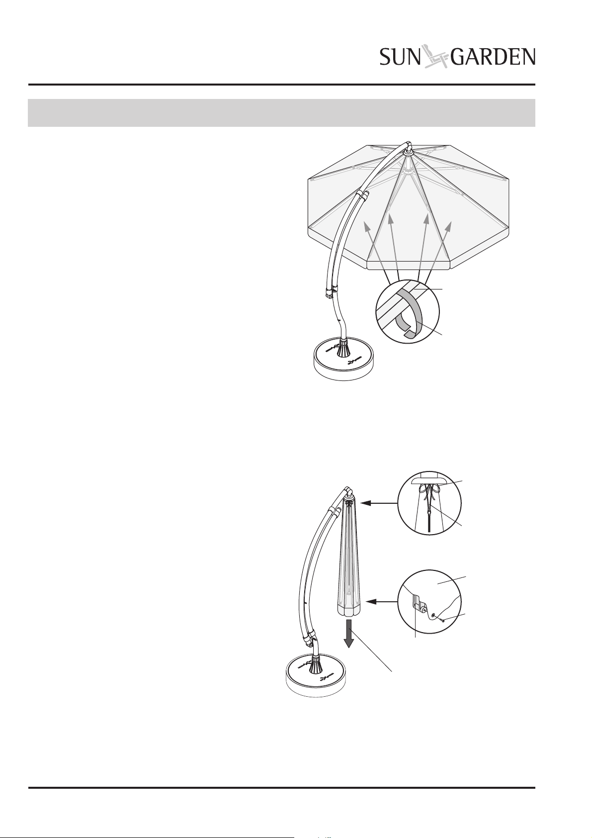
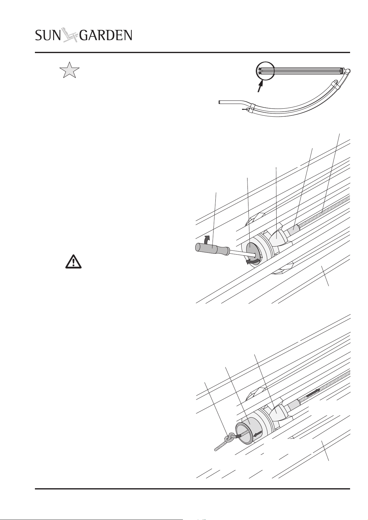
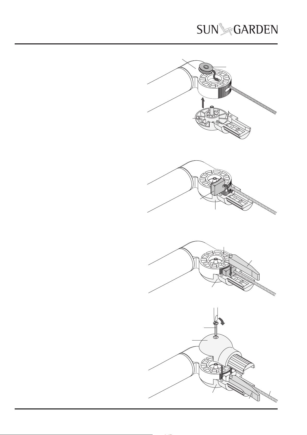
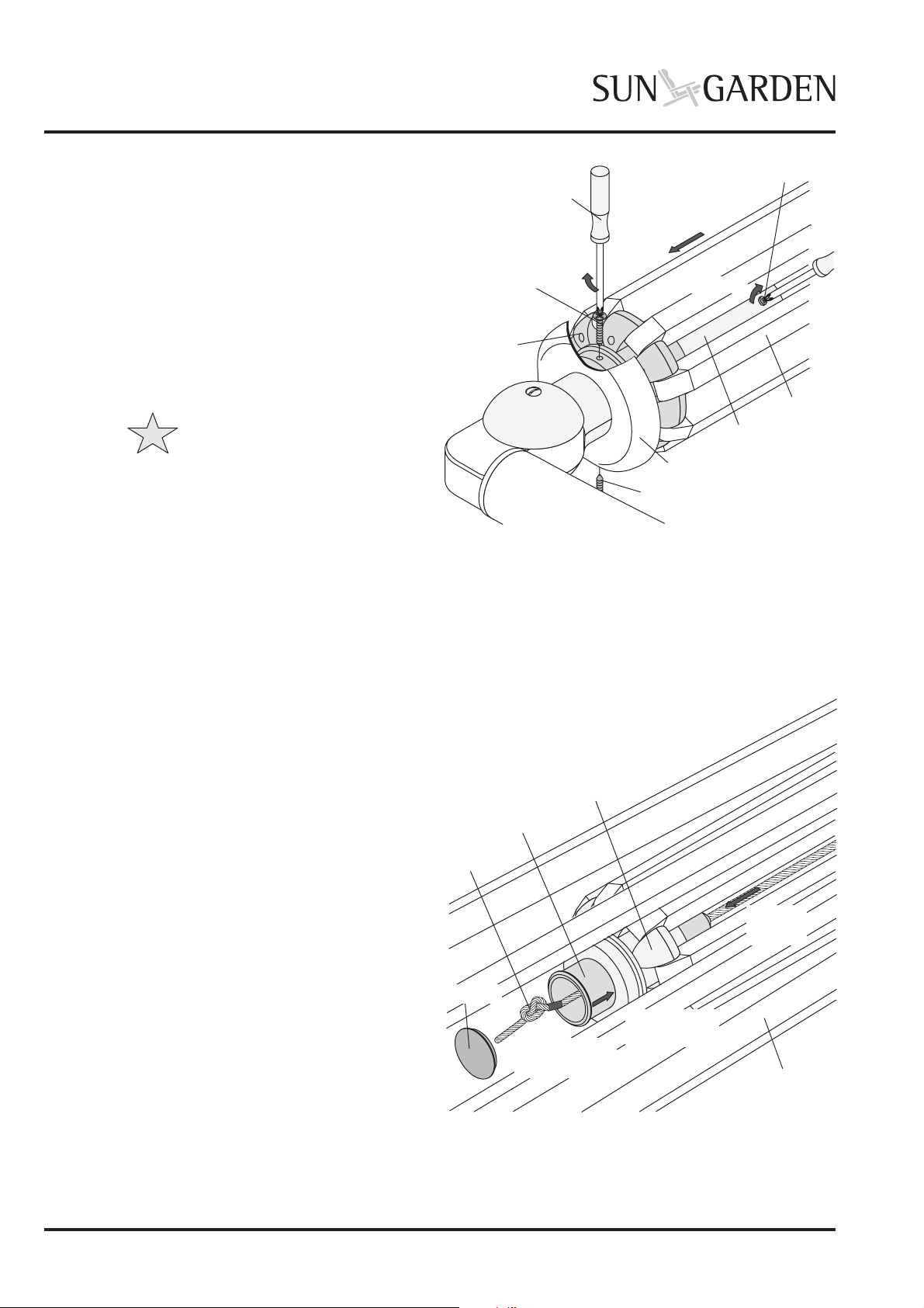
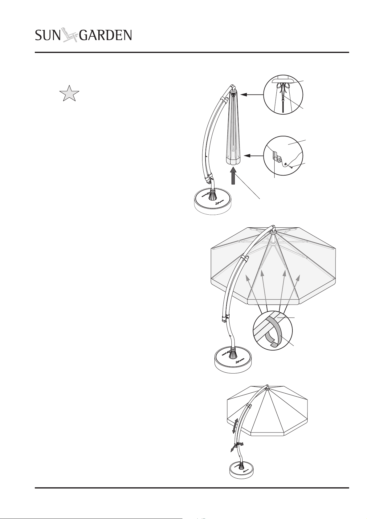
sun garden Easy Sun Setup guide

Page 1
Issue: 04.2004 Subject to alterations due to technical improvements.
REPAIR INSTRUCTIONS:
BALL JOINT
Included in delivery Tools required
Safety note
These repair instructions are intended only for persons
with experience of using the tools required.
Please read the instructions carefully through before
working. Damages caused by non-observance of the
instructions are excluded from any liability and guarantee
The repairs described below should be carried out by
two people.
Caution: Risk of trapping!
There is increased risk of trapping at all
sunshade frame joints.
• Bear these hazard locations in mind
while working.
❏Screwdriver; blade width: 3.5 mm
❏Screwdriver; blade width: 7 mm
❏Phillips screwdriver No. 2
Contents
The repair instructions describe replacing the
• ball joint
in the Easy Sun
PARASOL Hanging
sunshade.
➂Cover for cable seat
➀Ball joint; consisting of:
Brake
block
Brake
lever
Axle
Ball joint upper part
Ball joint lower part
fixing screw, M6 x 45
Deflector pulley
Installation
1.0 Removing sunshade cover ___________ 2
2.0 Releasing the cable ________________ 3
3.0 Removing the sunshade frame ________ 4
4.0 Remove ball joint __________________ 4
5.0 Assembling the ball joint ____________ 5
6.0 Assembling the guide tube ___________ 7
7.0 Assembling the sunshade frame ______ 8
8.0 Threading and fixing the cable ________ 8
9.0 Refitting the sunshade cover __________ 9
10.0 Final check _______________________ 9

Page 2 Issue: 04.2004
Subject to alterations due to technical improvements.
REPAIR INSTRUCTIONS:
BALL JOINT
➭Close sunshade and remove all screws in
the sunshade cover bottom fixing with a
Phillips screwdriver.
➭Open zip and closing tape in top cover fixing
and remove cover downwards from
sunshade frame.
Installation
Sunshade frame
Velcro band
Closing tape
Zip
Top cover fixing
Bottom cover fixing
Fixing screw
Sunshade
cover
Bracket for
sunshade cover
Pull downwards from
sunshade frame
➭Close sunshade and remove all screws in
the sunshade cover bottom fixing with a
Phillips screwdriver.
➭Open zip and closing tape in top cover fixing
and remove cover downwards from
sunshade frame.
1.0 Removing sunshade cover
➭Open the sunshade about half-way.
➭Release all material velcro bands on the
sunshade frame from the inside.

Page 3
Issue: 04.2004 Subject to alterations due to technical improvements.
REPAIR INSTRUCTIONS:
BALL JOINT
2.0 Releasing the cable
The seat for the cable is located on the lower
frame seat.
Cable seat position
➭Jab screwdriver through cable seat cover
and lever off.
➭Remove the cable from the cable seat
forwards and mark the position of the knot
with adhesive tape.
➭Undo the knot and remove the cable from the
seat.
➭Withdraw the cable seat downwards out of the
frame seat.
Caution: Risk of injury!
It is very easy to cause injuries
with the screwdriver.
• Do not hold any limbs in
the way of the screwdriver.
Note
To continue repair work lay sunshade
on floor.
To protect sunshade against damage
you should place it on a suitable
underlay (cardboard, carpet roll etc.).
Cable seat
Cable
Sunshade
frame
Lower
frame seat
1. Mark
knot and undo
2. Pull cable
out
3. Remove
cable seat
Cable seat
Cover
Cable
Jab in
and lever off
Screwdriver
Sunshade
frame
Lower
frame seat

Page 4 Issue: 04.2004
Subject to alterations due to technical improvements.
REPAIR INSTRUCTIONS:
BALL JOINT
Upper frame seat position
Upper frame
position
Frame arm
Guide tube
Fixing screw
Loosen
Push
downwards
Protective cap
Phillips screwdriver
Fixing screw
Loosen
Locking screw
4.0 Remove ball joint
➭Pull guide tube off ball joint.
➭Loosen fixing screw in ball joint upper part
with screwdriver and remove upper part.
3.0 Removing the sunshade frame
➭Loosen and remove side fixing screws
between protective cap and upper frame
seat with Phillips screwdriver.
➭Unscrew the guide bush locking screw
located on the side of the guide tube.
➭Push the complete frame downwards out
of the guide tube.
➭Push the protective cap downwards off the
guide tube.
Note
Only pull the guide tube far enough so
that the cable is not pulled out of it. This
avoids you having to thread the cable in
when re-assembling.
Guide tube
Ball joint upper part
Fixing screw
Loosen
Pull
downwards

Page 5
Issue: 04.2004 Subject to alterations due to technical improvements.
REPAIR INSTRUCTIONS:
BALL JOINT
➭Remove brake lever and brake block from
ball joint lower part.
Rermove brake
part
Ball joint lower part
Brake lever
Brake block
Articulated
joint part
Ball joint lower part
Deflector
pulley
Articulated
joint part
Remove
5.0 Assembling the ball joint
➭Dismantle new ball joint and remove deflector
pulley, brake lever and brake block.
Note
Leave the deflector pulley axle
in part of the ball joint and then
tighten the fixing screw.
Brake
block
Brake
lever
Deflector pulley axle
Ball joint upper part
Ball joint lower part
Fixing screw, M6 x 45
Deflector pulley
➭Withdraw ball joint lower part from
articulated joint part.
➭Remove deflector pulley from articulated
joint part.

Page 6 Issue: 04.2004
Subject to alterations due to technical improvements.
REPAIR INSTRUCTIONS:
BALL JOINT
➭Place deflector pulley in articulated joint part
and thread cable in the deflector pulley guide
groove.
➭Set the lower part provided with an axle into
the articulated joint part and insert the axle
into the deflector pulley.
Please give special attention to the following:
• make sure the deflector pulley does not
jam in the articulated jont.
• ensure the cable is placed exactly in
the deflector pulley guide.
Ball joint lower part
Deflector pulley
Articulated
joint part
Insert
Locate and
thread cable
Locate and
thread cable
Ball joint lower part
Brake block
Ball joint lower part
Brake lever
Pivot pin
Ball joint upper part
Fixing screw
Cable
Brake lever
Tighten
Ball joint lower part
➭Put ball joint upper part on.
Please give special attention to the following:
• ensure that the brake lever pivot pin and
the upper part guide pin locates in the
corresponding bores.
• ensure that the cable can move freely in the
ball joint.
➭Screw upper part fixing screw in and tighten.
➭Place brake lever with the pivot pin in the
corresponding bore (●) in the lower part.
➭Place brake block in the assembled lower
part and place cable in the brake block
recess.

Page 7
Issue: 04.2004 Subject to alterations due to technical improvements.
REPAIR INSTRUCTIONS:
BALL JOINT
6.0 Assembling the guide tube
➭Insert brake tube into guide tube.
Please give special attention to the following:
• ensure that the supporting roller is located
in the brake wedge (see Detail 1).
• that the guides at the bottom end
of the brake tube locate in the grooves in
the centring bush in the guide
tube (see Detail 2).
Guide tube
Brake tube
Supporting
roller
Brake
wedge
Centring bush
Detail 1:
Brake
wedge
Detail 2:
Centring bush
Brake
wedge
Brake tube Centring bush
Guide tube
Ball joint
Fixing bores
Brake wedge
Brake lever
Cable seat
Guide tube
Centring bush
Press in
Swivel
➭Check the swivel brake function before further
assembly.
Test sequence:
• remove cable seat from lower frame seat.
• press the cable seat pins into guide tube
centring bushes and try swivelling the
ball joint.
The brake is OK when the ball joint can only
be swivelled with difficulty or not at all.
➭Push guide tube onto ball joint shaft as far as
stop, and align to fixing bores provided there.
Please give special attention to the following:
• the exact position of the brake wedge
relative to the brake lever .
• free movement of cable within
the guide tube.

Page 8 Issue: 04.2004
Subject to alterations due to technical improvements.
REPAIR INSTRUCTIONS:
BALL JOINT
Note
• When screwing in the fixing
crews, ensure that the drill
holes do not slip.
• Overtightening of the fixing
screws leads to destruction
of the guide tube.
8.0 Threading and fixing the cable
➭Push the cable seat into the frame seat from
below.
➭Thread the cable in the cable seat.
➭Knot the cable at the adhesive tape marking.
➭Close off the opening for the cable seat by
pushing in the cover.
Cable seat
Cable
Sunshade
frame
Lower
frame seat
3. Knot cable
at marking
1. Push in
cable seat
2. Pull
cable
Cover
Upper
frame
position
Frame arm
Guide tube
Fixing
screw
Protective cap
Phillips
screwdriver
Fixing screw
Tighten
Push
upwards
Tighten
7.0 Assembling the sunshade frame
➭Push protective cap and upper sunshade frame
frame seat onto guide tube as far as the stop.
➭Align the side bores in the upper frame seat
with the fixing bores in the
guide tube and ball joint.
➭Screw in the fixing screws in the frame seat
with a Phillips screwdriver and tighten.
Locking screw
➭Screw in the guide bush locking screw
located on the side of the guide tube.

Page 9
Issue: 04.2004 Subject to alterations due to technical improvements.
REPAIR INSTRUCTIONS:
BALL JOINT
Note
Before refitting the sunshade cover
place the sunshade in the sunshade
stand. Use a ladder to refit the cover.
➭Push the sunshade cover onto the sunshade
frame from below.
➭Close the closing tape and zip in the upper
cover fixing.
➭Screw in all screws on the lower cover fixing.
Pull onto sunshade
frame from below
9.0 Refitting the sunshade cover
Closing tape
Zip
Top cover fixing
Bottom cover fixing
Fixing screw
Sunshade
cover
Bracket for
sunshade cover
Sunshade frame
Velcro band
➭Open the sunshade about half-way and
fix all velcro bands to the sunshade
frame.
10.0 Final check
Check all sunshade adjustment functions for
correct functioning after you have completed
the repairs.
Other manuals for Easy Sun
4
Table of contents
Other sun garden Patio Furniture manuals
Popular Patio Furniture manuals by other brands

Wisteria Lane
Wisteria Lane KX-AL01-3 instruction manual

Hanover
Hanover Lavallette LAVDN7PCSW-BLU owner's manual

Style selections
Style selections UCM01601D Quick reference guide

Weltevree
Weltevree PATIOBENCH 2-3 SEATER manual

Sunburst
Sunburst SB-7 Assembly instruction

Alice's Garden
Alice's Garden HU3X3ROOF manual