REPAIR INSTRUCTIONS:
CABLE
Page 1
Issue: 06.2004 Subject to alterations due to technical improvements.
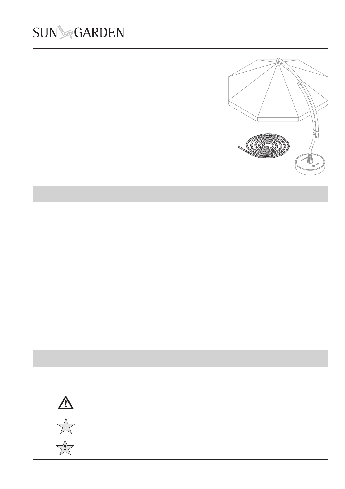
The repair instructions describe replacing the
• Cable
in the Easy Sun
PARASOL Sunshade.
These repair instructions are intended only for persons with
experience of using the tools required.
Please read the instructions carefully through before working.
Damages caused by non-observance of the instructions are
excluded from any liability and guarantee.
We cannot guarantee that the repair described can be carried out
without damaging the components involved.
The repairs described below should be carried out by two people.
Contents
1.0 Safety information
1.1 Important symbols
Special information is labelled with the following graphics in the manual:
Note
This symbol identifies information which can avoid damage to the sunshade.
Caution!
This symbol identifies information which refers to danger of injury and accident.
Note
This symbol identifies general tips for handling.
1.0 Safety information _____________ 1
1.1 Important symbols ________________ 1
1.2 Safety information ________________ 2
2.0 Included in delivery ____________ 2
3.0 Tools ________________________ 3
4.0 Preparation ___________________ 3
4.0 Removing sunshade cover __________ 3
4.3 Remove the defective cable
from the frame ___________________ 4
4.4 Removing the sunshade frame _______ 4
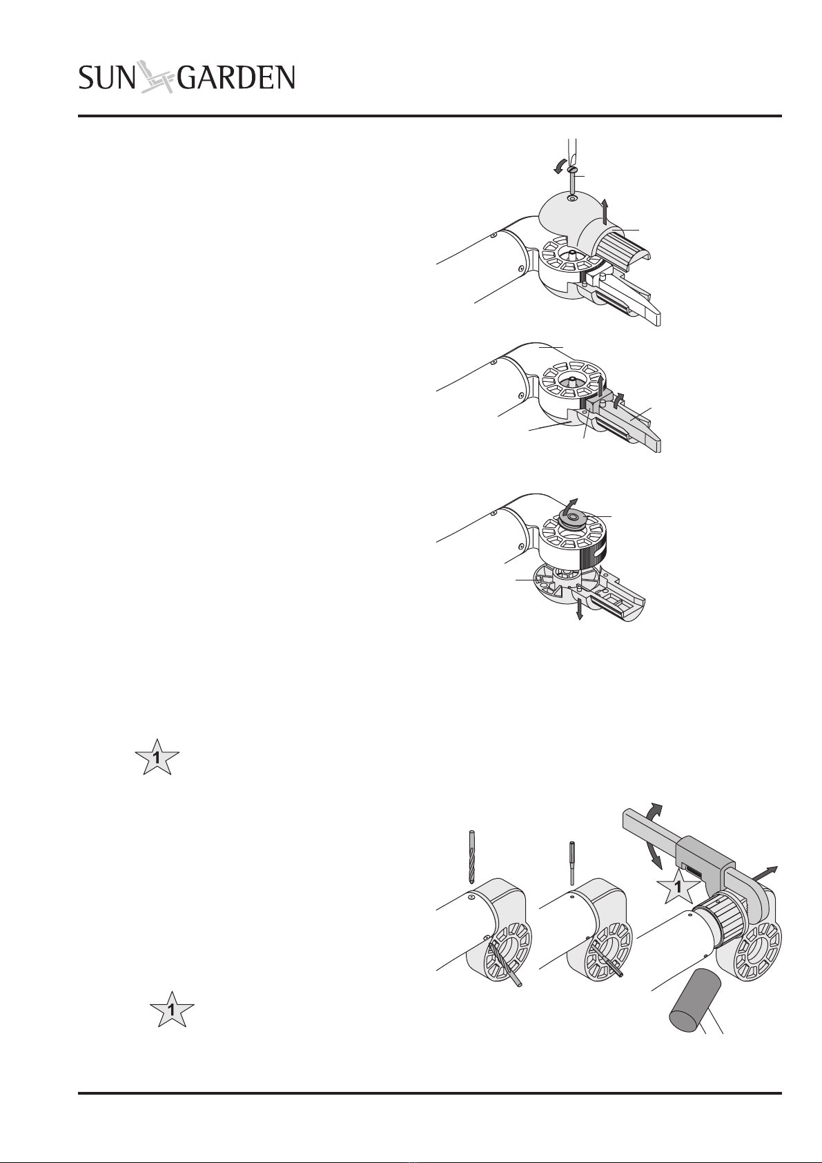
4.5 Remove ball joint _________________ 5
4.6 Remove articulated joint part ________ 5
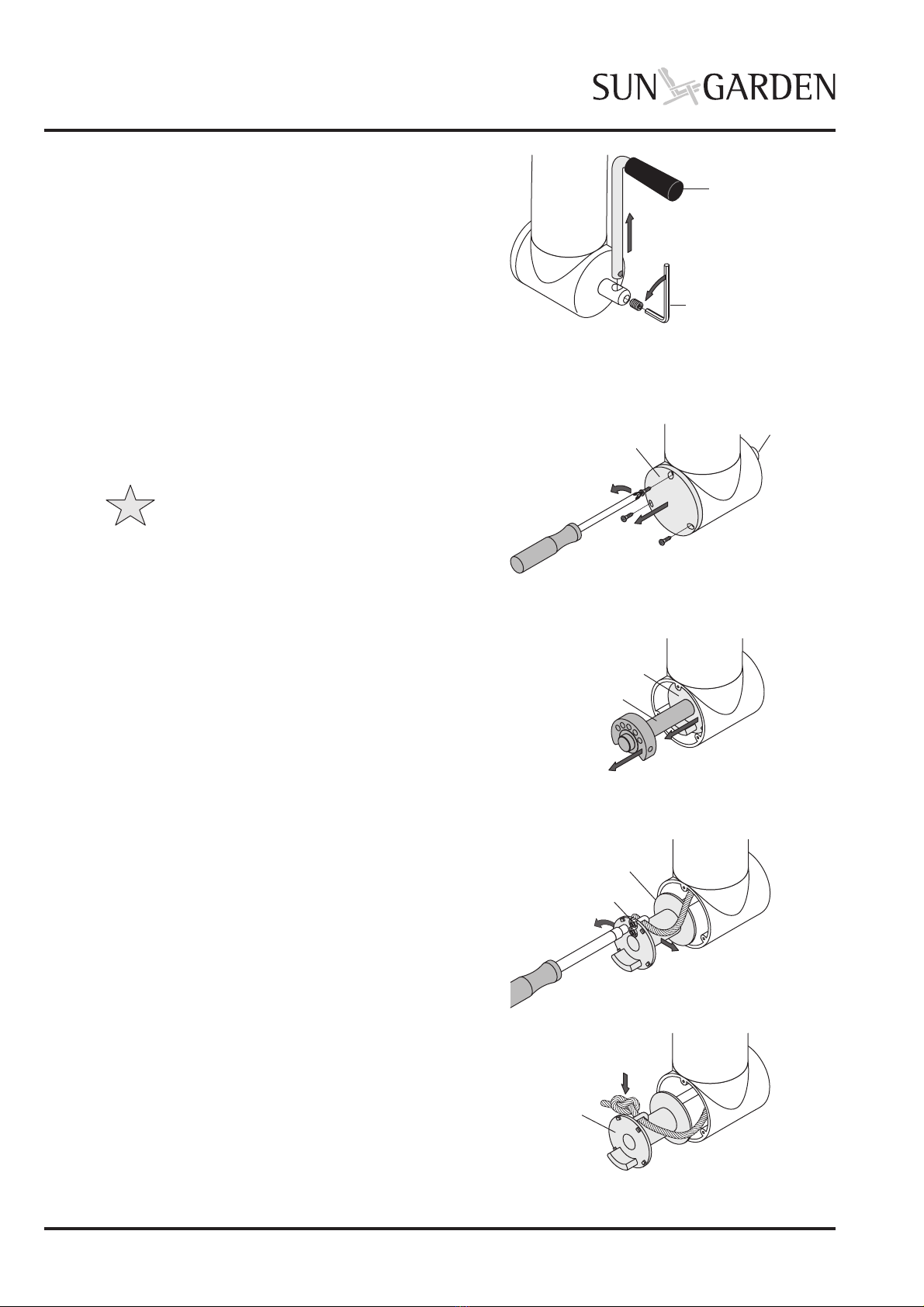
4.7 Remove winch handle _____________ 6
4.8 Removing the winch housing cover ___ 6
4.9 Removing cable drum _____________ 6
5.0 Fitting new cable ______________ 7
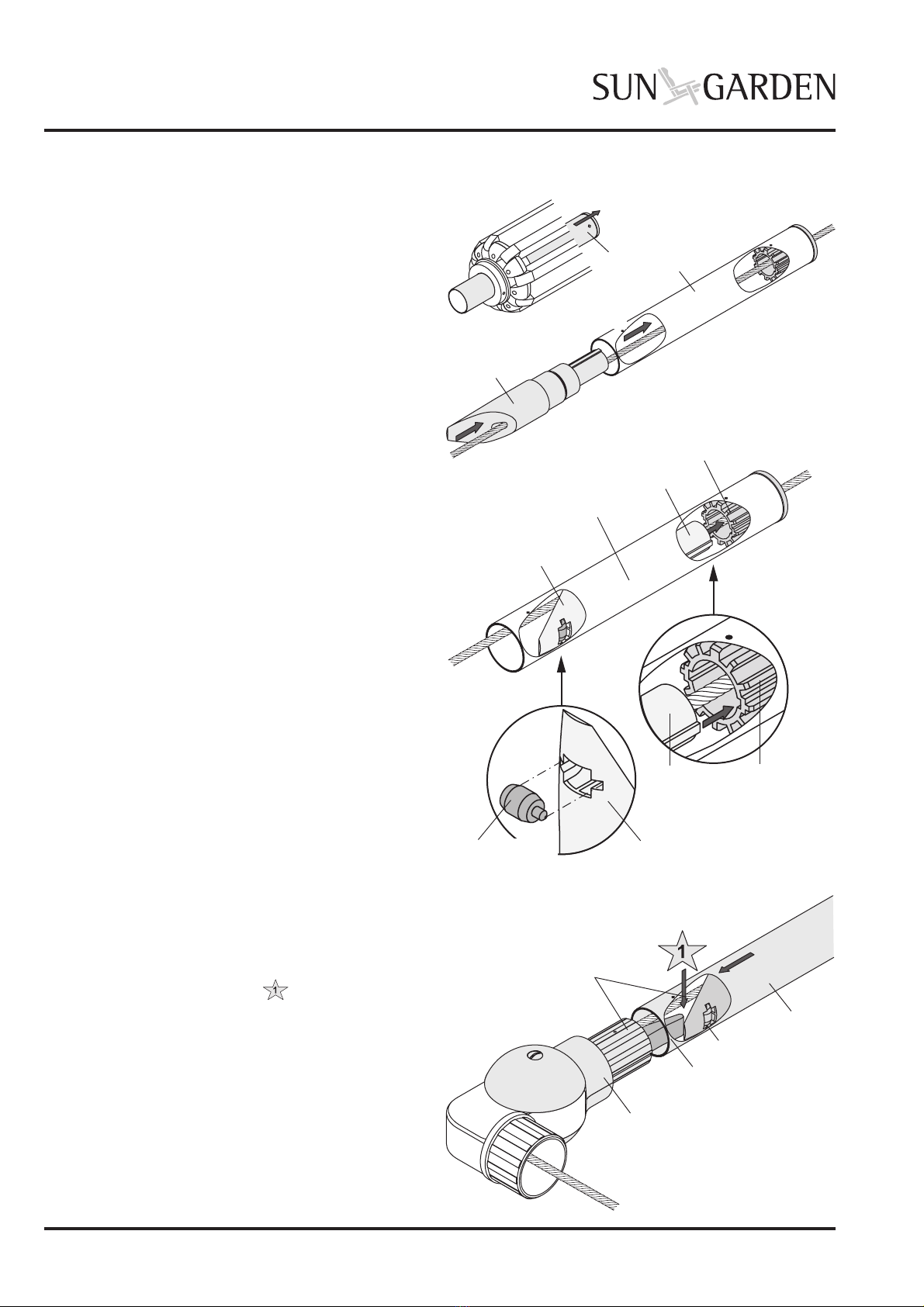
8.0 Thread the cable in the articulated
joint part _______________________ 7
5.2 Thread the cable through the guide
tube and complete the ball joint ______ 8
5.3 Thread the cable through the guide ___ 9
tube and complete the ball joint ______ 9
5.4 Assembling the sunshade frame ____ 10
5.5 Threading the cable into the bottom _ 10
middle piece and fixing ___________ 10
5.6 Inserting the cable drum __________ 11
5.7 Inserting the winch handle _________ 11
5.8 Fitting the winch housing cover _____ 12
5.9 Refitting the sunshade cover _______ 12
6.0 Final check __________________ 12