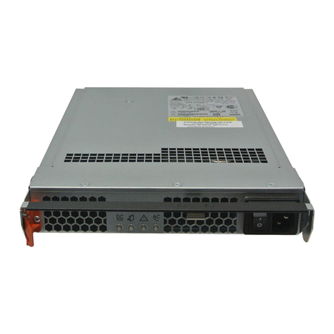
Sun Microsystems Sun StorEdge T3 Setup guide

Sun Microsystems, Inc.
901 San Antonio Road
Palo Alto, CA 94303-4900 U.S.A.
650-960-1300
Sun StorEdge™T3 and T3+ Array
Installation, Operation,
and Service Manual
Part No. 816-0773-10
August 2001, Revision A

Please
Recycle
Copyright 2001 Sun Microsystems, Inc., 901 San Antonio Road, Palo Alto, CA 94303-4900 U.S.A. All rights reserved.
This product or document is distributed under licenses restricting its use, copying, distribution, and decompilation. No part of this product or
document may be reproduced in any form by any means without prior written authorization of Sun and its licensors, if any. Third-party
software, including font technology, is copyrighted and licensed from Sun suppliers.
Parts of the product may be derived from Berkeley BSD systems, licensed from the University of California. UNIX is a registered trademark in
the U.S. and other countries, exclusively licensed through X/Open Company, Ltd.
Sun, Sun Microsystems, the Sun logo, AnswerBook2, docs.sun.com, SunSolve, JumpStart, StorTools, Sun StorEdge, and Solaris are trademarks,
registered trademarks, or service marks of Sun Microsystems, Inc. in the U.S. and other countries. All SPARC trademarks are used under license
and are trademarks or registered trademarks of SPARC International, Inc. in the U.S. and other countries. Products bearing SPARC trademarks
are based upon an architecture developed by Sun Microsystems, Inc.
The OPEN LOOK and Sun™ Graphical User Interface was developed by Sun Microsystems, Inc. for its users and licensees. Sun acknowledges
the pioneering efforts of Xerox in researching and developing the concept of visual or graphical user interfaces for the computer industry. Sun
holds a non-exclusive license from Xerox to the Xerox Graphical User Interface, which license also covers Sun’s licensees who implement OPEN
LOOK GUIs and otherwise comply with Sun’s written license agreements.
Federal Acquisitions: Commercial Software—Government Users Subject to Standard License Terms and Conditions.
DOCUMENTATION IS PROVIDED “AS IS” AND ALL EXPRESS OR IMPLIED CONDITIONS, REPRESENTATIONS AND WARRANTIES,
INCLUDING ANY IMPLIED WARRANTY OF MERCHANTABILITY, FITNESS FOR A PARTICULAR PURPOSE OR NON-INFRINGEMENT,
ARE DISCLAIMED, EXCEPT TO THE EXTENT THAT SUCH DISCLAIMERS ARE HELD TO BE LEGALLY INVALID.
Copyright 2001 Sun Microsystems, Inc., 901 San Antonio Road, Palo Alto, CA 94303-4900 Etats-Unis. Tous droits réservés.
Ce produit ou document est distribué avec des licences qui en restreignent l’utilisation, la copie, la distribution, et la décompilation. Aucune
partie de ce produit ou document ne peut être reproduite sous aucune forme, par quelque moyen que ce soit, sans l’autorisation préalable et
écrite de Sun et de ses bailleurs de licence, s’il y en a. Le logiciel détenu par des tiers, et qui comprend la technologie relative aux polices de
caractères, est protégé par un copyright et licencié par des fournisseurs de Sun.
Des parties de ce produit pourront être dérivées des systèmes Berkeley BSD licenciés par l’Université de Californie. UNIX est une marque
déposée aux Etats-Unis et dans d’autres pays et licenciée exclusivement par X/Open Company, Ltd.
Sun, Sun Microsystems, le logo Sun, AnswerBook2, docs.sun.com, SunSolve, JumpStart, StorTools, Sun StorEdge, et Solaris sont des marques
de fabrique ou des marques déposées, ou marques de service, de Sun Microsystems, Inc. aux Etats-Unis et dans d’autres pays. Toutes les
marques SPARC sont utilisées sous licence et sont des marques de fabrique ou des marques déposées de SPARC International, Inc. aux Etats-
Unis et dans d’autres pays. Les produits portant les marques SPARC sont basés sur une architecture développée par Sun Microsystems, Inc.
L’interface d’utilisation graphique OPEN LOOK et Sun™ a été développée par Sun Microsystems, Inc. pour ses utilisateurs et licenciés. Sun
reconnaît les efforts de pionniers de Xerox pour la recherche et le développement du concept des interfaces d’utilisation visuelle ou graphique
pour l’industrie de l’informatique. Sun détient une licence non exclusive de Xerox sur l’interface d’utilisation graphique Xerox, cette licence
couvrant également les licenciés de Sun qui mettent en place l’interface d’utilisation graphique OPEN LOOK et qui en outre se conforment aux
licences écrites de Sun.
LA DOCUMENTATION EST FOURNIE “EN L’ETAT” ET TOUTES AUTRES CONDITIONS, DECLARATIONS ET GARANTIES EXPRESSES
OU TACITES SONT FORMELLEMENT EXCLUES, DANS LA MESURE AUTORISEE PAR LA LOI APPLICABLE, Y COMPRIS NOTAMMENT
TOUTE GARANTIE IMPLICITE RELATIVE A LA QUALITE MARCHANDE, A L’APTITUDE A UNE UTILISATION PARTICULIERE OU A
L’ABSENCE DE CONTREFAÇON.
Contents iii
Contents
Preface xi
1. Sun StorEdge T3 and T3+ Array Overview 1-1
1.1 Product Description 1-2
1.2 Array Features 1-3
1.3 Components 1-5
1.3.1 Disk Drive 1-5
1.3.2 Controller Card 1-6
1.3.2.1 Sun StorEdge T3 Array Controller 1-6
1.3.2.2 Sun StorEdge T3+ Array Controller 1-7
1.3.3 Interconnect Card 1-7
1.3.4 Power and Cooling Unit 1-8
1.4 Architecture 1-8
1.5 Supported Configurations 1-9
2. Installation 2-1
2.1 Preparing for the Installation 2-2
2.2 Inspecting the Array 2-3
2.3 Editing the Host Files 2-4
2.4 Installing the Array 2-7
2.5 Connecting the Cables 2-8

iv Sun StorEdge T3 and T3+ Array Installation, Operation, and Service Manual • August 2001
2.6 Powering On and Verifying the Hardware Configuration 2-14
2.7 Establishing a Network Connection 2-16
2.8 Verifying the Firmware Level and Configuration 2-19
2.9 Installing the Administration Tools 2-25
2.10 Defining and Mounting Volumes 2-25
2.10.1 Workgroup Configuration 2-27
2.10.2 Enterprise Configuration 2-29
2.11 Changing the Default Configuration 2-32
2.12 Connecting the Host System 2-33
2.12.1 Verifying the Data Host Connection 2-33
2.12.2 Establishing Logical Volumes on the Host 2-34
2.12.3 Creating Soft Partitions on the Data Host 2-35
2.12.4 Establishing Alternate Pathing on the Host 2-35
3. Operation 3-1
3.1 Powering Off and On 3-1
3.1.1 Powering Off 3-1
3.1.2 Powering On 3-2
3.2 Reconfiguring the Array Settings 3-3
3.2.1 Unit Volume Configurations 3-3
3.2.2 RAID Levels 3-4
3.2.2.1 RAID 0 3-5
3.2.2.2 RAID 1 3-5
3.2.2.3 RAID 5 3-5
3.2.3 Cache Modes 3-6
3.2.4 Disabling and Reconstructing a Drive 3-8
3.3 Monitoring the Array 3-9
3.3.1 Sun StorEdge Component Manager 3-9
3.3.2 SNMP Notification 3-9
3.3.3 syslog Error Reports 3-10

Contents v
4. Troubleshooting 4-1
4.1 Analyzing the Problem 4-1
4.1.1 Host-Generated Message 4-1
4.1.2 Sun StorEdge Component Manager 4-2
4.1.3 Telnet Session 4-2
4.1.4 Array LEDs 4-3
4.1.4.1 Disk Drive LEDs 4-3
4.1.4.2 Power and Cooling Unit LEDs 4-4
4.1.4.3 Interconnect Card LEDs 4-6
4.1.4.4 Controller Card LEDs 4-7
4.2 Channel Connection Failures 4-9
4.3 FRU Failures 4-10
5. Service 5-1
5.1 Preparing for Service 5-2
5.2 Removing and Replacing Components 5-2
5.2.1 Disk Drives 5-3
5.2.1.1 Disk Drive LEDs 5-3
5.2.1.2 Removing and Replacing a Disk Drive 5-4
5.2.2 Power and Cooling Units 5-7
5.2.2.1 Power and Cooling Unit LEDs 5-8
5.2.2.2 Removing and Replacing a Power and Cooling Unit 5-
8
5.2.3 UPS Battery 5-10
5.2.3.1 Battery Maintenance 5-10
5.2.3.2 Removing and Replacing the UPS Battery 5-11
5.2.4 Interconnect Cards 5-11
5.2.4.1 Interconnect Card LEDs 5-11
5.2.4.2 Removing and Replacing an Interconnect Card 5-12
5.2.5 Controller Card 5-14
5.2.5.1 Controller Card LEDs 5-14

vi Sun StorEdge T3 and T3+ Array Installation, Operation, and Service Manual • August 2001
5.2.5.2 Removing and Replacing a Controller Card 5-14
5.2.6 Chassis 5-16
5.3 Upgrading Firmware 5-16
5.3.1 Upgrading Sun StorEdge T3+ Array Controller Firmware 5-17
5.3.1.1 To Upgrade the Level 2 Image 5-17
5.3.1.2 To Upgrade the Level 3 Image 5-19
5.3.2 Upgrading Sun StorEdge T3 Array Controller Firmware 5-20
5.3.2.1 To Upgrade Controller Firmware 5-21
5.3.2.2 To Upgrade the Controller EPROM Firmware: 5-22
5.3.3 Upgrading Interconnect Card Firmware 5-24
5.3.4 Upgrading Disk Drive Firmware 5-25
A. Specifications A-1
A.1 Power Specifications A-1
A.2 Environmental Specifications A-2
A.3 Mechanical Specifications A-3
A.4 Cable Specifications A-3
B. Illustrated Parts B-1
Glossary Glossary-1

vii
Figures
FIGURE 1-1 Sun StorEdge T3 Array 1-3
FIGURE 1-2 Disk Drives (Front View) 1-5
FIGURE 1-3 Controller Card (Rear View) 1-6
FIGURE 1-4 Sun StorEdge T3 Array Controller Card Front Panel 1-6
FIGURE 1-5 Sun StorEdge T3+ Array Controller Card Front Panel 1-7
FIGURE 1-6 Interconnect Cards (Rear View) 1-7
FIGURE 1-7 Power and Cooling Units (Rear View) 1-8
FIGURE 1-8 Workgroup Configuration 1-9
FIGURE 1-9 Enterprise Configuration 1-10
FIGURE 2-1 Removing the Front Panel 2-3
FIGURE 2-2 Serial Number and MAC Address on Pull-out Tab 2-4
FIGURE 2-3 Sun StorEdge T3 Array Cables and Adapters 2-9
FIGURE 2-4 Sun StorEdge T3+ Array Cables 2-9
FIGURE 2-5 Connecting the Fiber-Optic Cable to the FC-AL Connector on a
Sun StorEdge T3+ Array 2-10
FIGURE 2-6 Connecting the Fiber-Optic Cable and MIA to the FC-AL Connector on a
Sun StorEdge T3 Array 2-11
FIGURE 2-7 Connecting the Ethernet Cable 2-11
FIGURE 2-8 Connecting the Power Cords 2-12
FIGURE 2-9 Connecting the Interconnect Cables 2-13

viii Sun StorEdge T3 and T3+ Array Installation, Operation, and Service Manual • August 2001
FIGURE 2-10 Fully Cabled Partner Group (Enterprise Configuration) 2-14
FIGURE 2-11 Power and Cooling Unit LEDs and Power Button Location 2-15
FIGURE 2-12 Disk Drive Physical Numbering 2-26
FIGURE 3-1 Power Switch Locations 3-2
FIGURE 4-1 Disk Drive LEDs (Viewed Through Front Cover) 4-3
FIGURE 4-2 Power and Cooling Unit LEDs 4-4
FIGURE 4-3 Interconnect Card LEDs 4-6
FIGURE 4-4 Sun StorEdge T3 Array Controller Card LEDs 4-7
FIGURE 4-5 Sun StorEdge T3+ Array Controller Card LEDs 4-8
FIGURE 5-1 Removing the Front Panel 5-4
FIGURE 5-2 Disk Drive Numbering 5-4
FIGURE 5-3 Releasing the Latch Handle 5-5
FIGURE 5-4 Removing a Disk Drive 5-6
FIGURE 5-5 Power Cords Connected to the Power and Cooling Units 5-7
FIGURE 5-6 Removing the Power and Cooling Unit 5-9
FIGURE 5-7 Removing the Interconnect Card 5-13
FIGURE 5-8 Removing the Controller Card 5-15
FIGURE B-1 Disk Drive in Canister B-2
FIGURE B-2 Sun StorEdge T3 Array Controller Card B-2
FIGURE B-3 Sun StorEdge T3+ Array Controller Card B-3
FIGURE B-4 Interconnect Card B-3
FIGURE B-5 Power and Cooling Unit B-3
FIGURE B-6 Cables, Adapters, and Cords B-4
FIGURE B-7 Door Assembly (Front Panel) B-5

ix
Tables
TABLE 1-1 Sun StorEdge T3 and T3+ Array Key Features—73-Gbyte Drive 1-4
TABLE 2-1 Drive Status Messages 2-27
TABLE 3-1 Volume Configuration Examples 3-4
TABLE 3-2 RAID 0 Data Blocks 3-5
TABLE 3-3 RAID 1 (1+0) Data Blocks 3-5
TABLE 3-4 RAID 5 Data Blocks 3-6
TABLE 3-5 Cache Transition States 3-7
TABLE 3-6 syslog Error Reporting Levels 3-10
TABLE 4-1 Disk Drive LED Descriptions 4-4
TABLE 4-2 Power and Cooling Unit LED Descriptions 4-5
TABLE 4-3 Interconnect Card LED Descriptions 4-6
TABLE 4-4 FC-AL Channel-Active LED Descriptions (Sun StorEdge T3 array) 4-7
TABLE 4-5 Controller Status LED Descriptions (Sun StorEdge T3 array) 4-7
TABLE 4-6 Sun StorEdge T3+ Array Controller Card LED Descriptions 4-8
TABLE A-1 Power Specifications A-1
TABLE A-2 Environmental Specifications A-2
TABLE A-3 Physical Specifications A-3
TABLE A-4 Cable Specifications A-3
TABLE B-1 Illustrated Parts B-1

xSun StorEdge T3 and T3+ Array Installation, Operation, and Service Manual • August 2001

xi
Preface
This manual contains information on how to install, operate, and service the Sun
StorEdge™ T3 and T3+ arrays. Most of the procedures in this manual can be
performed by an experienced system administrator.
Before You Read This Book
Read the safety information in the Sun StorEdge T3 and T3+ Array Regulatory and
Safety Compliance Manual that is included with the array before attempting the
installation. Make sure you have prepared for the installation by reviewing the Sun
StorEdge T3 and T3+ Array Site Preparation Guide and the Sun StorEdge T3 and T3+
Array Configuration Guide. These guides are available on the Sun™ documentation
web site or from your Sun representative.
Work with your Sun representative to determine if you require any external
hardware or software products for using this device. Being prepared with this
knowledge and the appropriate tools will simplify the installation.
How This Book Is Organized
This manual is organized as follows:
Chapter 1 provides an overview of the Sun StorEdge T3 and T3+ arrays, describing
features, components, architecture, and supported configurations.
Chapter 2 describes how to install the array in either a single-unit or partner-group
configuration.

xii Sun StorEdge T3 and T3+ Array Installation, Operation, and Service Manual • August 2001
Chapter 3 describes options for operating your array, such as reconfiguring the
default settings and monitoring array activity.
Chapter 4 provides information on how to approach troubleshooting the array and
references troubleshooting tools.
Chapter 5 describes how to service the major components of the array and how to
upgrade array firmware.
Appendix A contains listings of array specifications.
Appendix B contains an illustrated parts list.
Glossary is a list of words and phrases and their definitions. Glossary terms are
italicized in the text.
Using UNIX Commands
This document contains some information on basic UNIX®commands and
procedures such as booting the devices. For further information, see one or more of
the following:
■AnswerBook2™ online documentation for the Solaris™ software environment
■Other software documentation that you received with your system

Preface xiii
Typographic Conventions
Shell Prompts
Typeface Meaning Examples
AaBbCc123 The names of commands, files,
and directories; on-screen
computer output
Edit your.login file.
Use ls -a to list all files.
% You have mail.
AaBbCc123 What you type, when
contrasted with on-screen
computer output
%su
Password:
AaBbCc123 Book titles, new words or terms,
words to be emphasized
Read Chapter 6 in the User’s Guide.
These are called class options.
You must be superuser to do this.
Command-line variable; replace
with a real name or value
To delete a file, type rm filename.
Shell Prompt
C shell machine_name%
C shell superuser machine_name#
Bourne shell and Korn shell $
Bourne shell and Korn shell superuser #
Sun StorEdge T3 and T3+ array :/:

xiv Sun StorEdge T3 and T3+ Array Installation, Operation, and Service Manual • August 2001
Related Documentation
Application Title Part Number
Latest array updates Sun StorEdge T3 and T3+ Array Release
Notes
816-1983
Installation overview Sun StorEdge T3 and T3+ Array Start Here 816-0772
Safety procedures Sun StorEdge T3 and T3+ Array Regulatory
and Safety Compliance Manual
816-0774
Site preparation Sun StorEdge T3 and T3+ Array Site
Preparation Guide
816-0778
Configuration Sun StorEdge T3 and T3+ Array
Configuration Guide
816-0777
Administration Sun StorEdge T3 and T3+ Array
Administrator’s Guide
816-0776
Cabinet installation Sun StorEdge T3 Array Cabinet Installation
Guide
806-7979
Disk drive specifications 18 Gbyte, 1-inch, 10K rpm Disk Drive
Specifications
806-1493
36 Gbyte, 10K rpm Inch Disk Drive
Specifications
806-6383
73 Gbyte, 10K rpm 1.6-Disk Drive
Specifications
806-4800
Sun StorEdge Component
Manager installation
Sun StorEdge Component Manager
Installation Guide - Solaris
806-6645
Sun StorEdge Component Manager
Installation Guide - Windows NT
806-6646
Using Sun StorEdge
Component Manager
Sun StorEdge Component Manager User’s
Guide
806-6647
Latest Sun StorEdge
Component Manager
Updates
Sun StorEdge Component Manager Release
Notes
806-6648

Preface xv
Accessing Sun Documentation Online
You can find the Sun StorEdge T3 and T3+ array documentation and other select
product documentation for Network Storage Solutions at:
http://www.sun.com/products-n-solutions/hardware/docs/
Network_Storage_Solutions
Sun Welcomes Your Comments
Sun is interested in improving its documentation and welcomes your comments and
suggestions. You can email your comments to Sun at:
Please include the part number (816-0773-10) of your document in the subject line of
your email.

xvi Sun StorEdge T3 and T3+ Array Installation, Operation, and Service Manual • August 2001

1-1
CHAPTER 1
Sun StorEdge T3 and T3+ Array
Overview
This chapter provides a high-level introduction to the Sun StorEdge T3 and T3+
arrays, and is organized as follows:
■“Product Description” on page 1-2
■“Array Features” on page 1-3
■“Components” on page 1-5
■“Architecture” on page 1-8
■“Supported Configurations” on page 1-9

1-2 Sun StorEdge T3 and T3+ Array Installation, Operation, and Service Manual • August 2001
1.1 Product Description
The Sun StorEdge T3 array is a high-performance, modular, scalable storage device
that contains an internal RAID controller and nine disk drives with Fibre Channel
connectivity to the data host. Extensive reliability, availability, and serviceability (RAS)
features include redundant components, notification of failed components, and the
ability to replace components while the unit is online. The Sun StorEdge T3+ array
provides the same features as the Sun StorEdge T3 array, and includes an updated
controller card with direct fiber-optic connectivity and additional memory for data
cache. The controller cards of both array models are described in more detail later in
this chapter.
The array can be used either as a standalone storage unit or as a building block,
interconnected with other arrays of the same type and configured in various ways to
provide a storage solution optimized to the host application. The array can be placed
on a table top or rackmounted in a server cabinet or expansion cabinet.
The array is sometimes called a controller unit, which refers to the internal RAID
controller on the controller card. Arrays without the controller card are called
expansion units. When connected to a controller unit, the expansion unit enables you
to increase your storage capacity without the cost of an additional controller. An
expansion unit must be connected to a controller unit to operate because it does not
have its own controller.
In this document, the Sun StorEdge T3 array and Sun StorEdge T3+ array are
referred to as the array, except when necessary to distinguish between models.
Note – The Sun StorEdge T3 and T3+ arrays are similar in appearance. In this
document, all illustrations labeled Sun StorEdge T3 array also apply to the Sun
StorEdge T3+ array, except when necessary to distinguish specific model features.
In these instances, the array model is specified.

Chapter 1 Sun StorEdge T3 and T3+ Array Overview 1-3
FIGURE 1-1 Sun StorEdge T3 Array
1.2 Array Features
Sun StorEdge T3 and T3+ arrays provide high reliability while being simple to
administer and maintain. The array features a design that supports high availability,
high performance, configuration flexibility, and scalability of bandwidth, capacity,
and input/output operations per second (IOPS). TABLE 1-1 provides an example of
these key features, depicting an array with nine 73-Gbyte drives.
Note – Other drive capacities are available. Check with your Sun representative for
more information on storage capacities that are currently available.

1-4 Sun StorEdge T3 and T3+ Array Installation, Operation, and Service Manual • August 2001
TABLE 1-1 Sun StorEdge T3 and T3+ Array Key Features—73-Gbyte Drive
Feature Sun StorEdge T3 Array Sun StorEdge T3+ Array
Capacity per unit 657 GB (9 x 73 GB drives) 657 GB (9 x 73 GB drives)
256 MB cache 1 GB cache
Performance per
controller
95+ MB/sec for large RAID 5
reads from disk (64K >)
95+ MB/sec for large RAID 5
reads from disk (64K >)
90+ MB/sec for large RAID 5 writes to disk 90+ MB/sec for large RAID 5 writes to disk
4,150 IOPS for 8 KB (100% cache hit reads) 7,200 IOPS for 8 KB (100% cache hit reads)
Connectivity per
controller
FC-AL host interface FC-AL host interface (LC-SFF to SC)
10BASE-T Ethernet network port 10/100BASE-T Ethernet network port
Scalability (one to
two units, one to
two controllers)
1,314 GB maximum capacity 1,314 GB maximum capacity
256 to 512 MB cache 1 to 2 GB cache
1 to 2 host Fibre Channel interfaces 1 to 2 host Fibre Channel interfaces
90 to 190 MB/sec bandwidth 90 to 190 MB/sec bandwidth
4,100 to 8,150 IOPS (100% cache hit reads) 7,200 to 14,360 IOPS (100% cache hit reads)
Reliability/
redundancy
RAID 0/1 (1+0)/5 RAID 0/1 (1+0)/5
Redundant back-end data loops Redundant back-end data loops
Redundant interconnect cards Redundant interconnect cards
Passive centerplane connector board Passive centerplane connector board
Redundant power and cooling units
and power cables
Redundant power and cooling units
and power cables
Redundant back-end FC-AL
interconnect cables
Redundant back-end FC-AL
interconnect cables
Redundant controller configuration Redundant controller configuration
Administration Telnet access (CLI interface) Telnet access (CLI interface)
Component Manager (GUI interface) Component Manager (GUI interface)
SNMP Version 1 SNMP Version 1
Other manuals for Sun StorEdge T3
5
This manual suits for next models
1
Table of contents
Other Sun Microsystems Speakers System manuals

Sun Microsystems
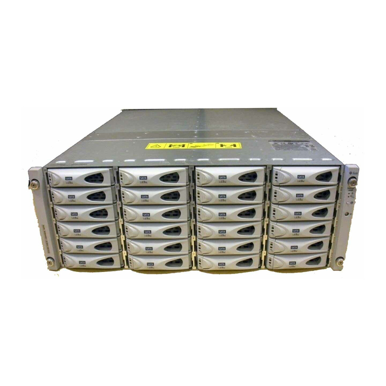
Sun Microsystems StorEdge T3+ Manual

Sun Microsystems
Sun Microsystems StorageTek 2500 Series Manual

Sun Microsystems
Sun Microsystems Sun StorEdge A1000 User manual

Sun Microsystems
Sun Microsystems J4500 User guide

Sun Microsystems
Sun Microsystems StorEdge 6130 User manual

Sun Microsystems
Sun Microsystems StorageTek 2500 Series Manual

Sun Microsystems
Sun Microsystems Sun Storage J4400 Operating instructions

Sun Microsystems
Sun Microsystems StorageTek 6140 Instruction Manual