Sun-Tech STP225S-16/Tem User manual


Version 20150101
Table of Contents
2 Purpose of this guide
General safety
Handling safety
Installation safety
Fire safety
5 Product Identication
6 Mechanical Installation
Selecting the location
General installation
Installation method
Attachment guidelines
11 Electrical Installation
General installation
Grounding
14 Maintenance
No.1
Global Installation Guide for
Suntech Power Photovoltaic Module
Version 20150101
* Please read carefully. This document is binding for any warranty case.
* Any installed PV system less than 500m from coastline, please refer to the Near-
coast installation manual.

Version 20150101 Version 20150101
Purpose of this guide
Handling safety
• Do not lift the module by grasping the module’s junction box or electrical leads.
• Do not drop the module or allow objects to fall on the module.
• Do not place any heavy or sharp objects on the module.
• Be cautious when placing the module down onto a surface, particularly when
placing it in a corner.
• Inappropriate transport and installation may break the module and void the
warranty.
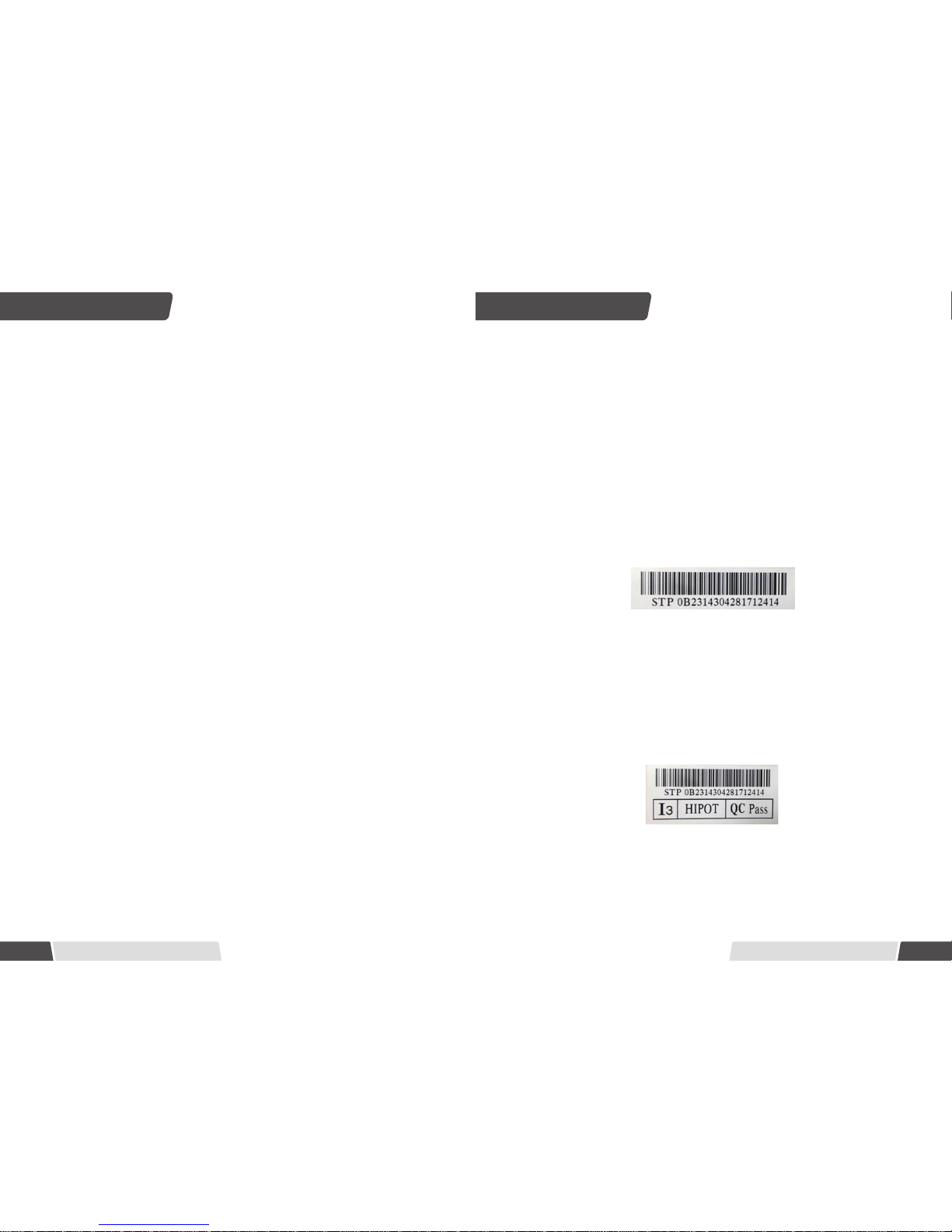
• Do not attempt to disassemble the modules, and do not remove any attached
nameplates or components from the modules.
• Do not apply paint or adhesive to the module top surface or backsheet.
• To avoid damage to the backsheet and cells, do not scratch, dent or hit the
backsheet. During the transportation, do not to apply direct pressure on the backsheet
or front glass.
• Do not drill holes in the frame. This may compromise the frame strength, cause
corrosion of the frame and void the warranty.
• Do not scratch the anodized coating of the frame (except for grounding
connections at the grounding connection point on the back side of the module). It may
cause corrosion of the frame or compromise the frame strength.
• A module with broken glass or torn backsheet cannot be repaired and must not be
used since contact with any module surface or the frame can cause an electric shock.
• Work only under dry conditions, and use only dry tools. Do not handle modules
under wet conditions unless wearing appropriate protective equipment.
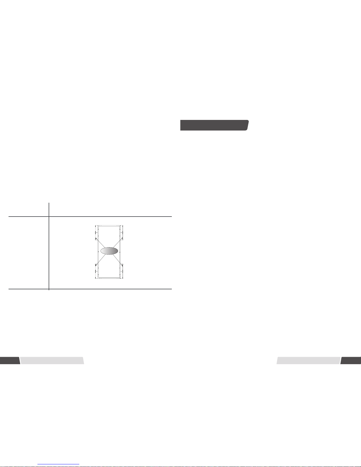
• When storing uninstalled modules outdoors for any period of time, always cover
the modules and ensure that the glass faces down on a soft flat surface to prevent
water from collecting inside the module and causing damage to exposed connectors.
No.3
• Only use equipment, connectors, wiring and support frames suitable for solar
electric systems.
• Do not use mirrors, other magniers or antically concentrated sunlight onto the
modules.
• Always use fall protection equipment when working from heights of 6 feet (183cm)
or above. Follow Occupational Safety and Health Act (OSHA) or local governing safety
regulations regarding Fall Protection. (UL Only)
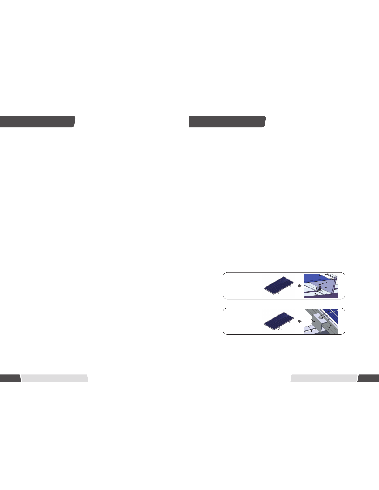
• Do not sit, stand, step or walk on any side of the module, including the frames.
• Do not permit any part of the module(s) to be submerged or allow for constant
water to soil the module(s) unless it's natural rain fall or periodic cleaning.
Purpose of this guide
• This guide contains information regarding the installation and safe handling of
Wuxi Suntech Power Co., Ltd photovoltaic module (hereafter referred to as “module”).
Wuxi Suntech Power Co., Ltd referred to as“Suntech”.
• Installers must read and understand this guide prior to installation. For any
questions, please contact Suntech's Global Quality & Customer Support department or
our local representatives for more detailed information. Installers must follow all safety
precautions as described in this guide as well as local requirement and regulations by
law or authorised organisations.
• Before installing a solar photovoltaic system, installers should familiarize
themselves with its mechanical and electrical requirements. Keep this guide in a safe
place for future reference (care and maintenance) and in case of sale or disposal of the
modules.
• Suntech modules are tested and certified for installation worldwide. Different
regions may have dierent regulations for solar PV installations. In this guide, hereafter
"IEC Only" is used to refer to regions where IEC standard applies, e.g. Europe, Middle
East, most of Asia Pacific countries; " UL Only " is used to refer to regions where UL
standard applies, e.g. United States, Canada; all other references are global.
General safety
• Modules that fall under this application class may be used in system operation
at more than 50V DC or 240W, where general contact access is anticipated. Modules
qualied for safety under IEC 61730-2 and within this application class are considered
to meet the requirements for Safety Class II. (IEC Only)
• Installing solar photovoltaic systems requires specialized skills and knowledge.
Installation must only be performed by qualied personnel.
• Installers must assume all risks of injury that might occur during installation,
including, but not limited to, the risk of electric shock.
• One single module may generate more than 30V DC when exposed to direct
sunlight. Contact with a DC voltage of 30V or more is potentially hazardous.
• Do not disconnect under load.
• PV modules generate electricity when exposed to sunlight. Number of modules
string connected can cause lethal shock and burn hazards. Only authorized and trained
person should have access to the modules.
• Photovoltaic solar modules convert light energy to direct current electrical energy.
They are designed for outdoor use. Modules can be ground mounted, mounted on
rooftops, vehicles or boats. The proper design of support structures lies within the
responsibility of the system designers and installers.
• When installing the system, abide to all local, regional and national statutory
regulations. Obtain a building permit if necessary.
• The electrical characteristics are within ±10 percent of the indicated values of
Isc, Voc and Pmax under standard test conditions (irradiance of 1000 W/m², AM 1.5
spectrum, and a cell temperature of 25°C (77°F) ).
No.2

Version 20150101 Version 20150101
No.5
2. Barcode: each individual module has a unique serial number. The serial number has
18 digits. The 15th and the 16th digits are the week code, and the 17th and the 18th
digits are the year code. For example, STP xxxxxxxxxxxxxx2414 means the module was
assembled and tested in the 24th week of 2014. Each module has only one bar code. It
is permanently attached to the interior of the module and is visible from the top front
of the module. This bar code is inserted prior to laminating.
Typical serial number barcode label
Do not remove any labels. Removing a label will make the Suntech warranty void.
3. Sorting label: four dierent marks are shown on this sticker. "QC Pass" assures that
the module has passed the quality control examination. "HIPOT" means that it has
passed the insulation test. Finally modules are sorted out according to their output
current, referred as a corresponding symbol "Ix" attached, in which x takes the value
1, 2 or 3(I3 marks physically the highest current). To get optimal performance out of a
string of modules it is recommended to connect only modules of the same "Ix" class (for
example only I2 modules) in one given string. The function of the "Barcode" please refer
to the "Barcode" instruction mentioned above.
Sorting label
Purpose of this guide Product identication
• Never open electrical connections or unplug connectors while the circuit is under
load.
• Contact with electrically charged parts of the modules, such as terminals, can
result in burns, sparks and lethal shock whether or not the module is connected.
• Do not touch the PV module unnecessarily during installation. The glass surface
and the frame may be hot; there is a risk of burns and electric shock.
• Do not work in the rain, snow or in windy conditions.
• Avoid exposing cables and connectors to direct sunlight and scratches or cuts in
order to prevent insulation degradation.
• Use only insulated tools that are approved for working on electrical installations.
• Keep children well away from the system while transporting and installing
mechanical and electrical components.
• Completely cover the module with an opaque material during installation to
prevent electricity from being generated.
• Do not wear metallic rings, watchbands, earrings, nose rings, lip rings or other
metallic objects while installing or troubleshooting photovoltaic systems.
• Follow the safety regulations(eg. safety rules for working on electrical power
plant stations) of your regions and for all other system components, including wires
and cables, connectors, charging regulators, inverters, storage batteries, rechargeable
batteries, etc.
• Under normal conditions, a photovoltaic module is likely to experience conditions
that produce more current and/or voltage than reported at standard test conditions.
Accordingly, the values of Isc and Voc marked on this module should be multiplied by a
factor of 1.25 when determining component voltage ratings, conductor current ratings,
minimum factor of fuse sizes, and size of controls connected to the PV output.
• Only use same connectors to connect modules to form a string, or connect to
another device. Removing the connectors will void the warranty.
Fire Safety
• Consult your local authority for guidelines and requirements for building or
structural re safety.
• Roof constructions and installations may affect the fire safety of a building;
improper installation may create hazards in the event of a re.
• Use components such as ground fault circuit breakers and fuses as required by
local authority.
• Do not use modules near equipment or in places where ammable gases may be
generated.
• The modules have been rated Fire Class C, and are suitable for mounting on to a
Class A roof.
No.4
Each module has three labels providing the following information:
1. Nameplate: describes the product type; rated power, rated current, rated voltage,
open circuit voltage, short circuit current, all as measured under standard test
conditions; weight, dimensions etc.; the maximum system voltage is 600 volts or 1000
volts depending on the product family DC for UL standard and 1000 volts DC for IEC
standard. Depending on the products some are UL/IEC listed to 1 000 volts while other
UL products are 600 volts. Check your nameplate or contact your local representative
for details.
Installation safety

Version 20150101 Version 20150101
Mechanical Installation
No.7
Installation methods
• Modules can be installed on the frame using mounting holes, clamps* or an
insertion system. Modules must be installed according to the following examples. Not
mounting the modules according to these instructions may void the warranty.
Module Frame
M8 Bolt
Mounting structure
M8 Nut
Flat washer
Split washer
Module installed
with mounting holes
M8 Bolt
Mounting structure
M8 Nut
Flat washer
Split washer
Clamps
Module
Module installed
with clamps
• Module can be installed in both landscape and portrait modes.
• The modules must be properly secured to their support so that they can withstand
live load conditions, including wind uplift, to the pressure they have been certied for.
It is the installer's responsibility to ensure that the clamps used to secure the modules
are strong enough.
* The minimum recommended length for each clamp is 50 mm.
General Installation
• Before installing modules check for any optical deviations. Any optical deviations
noticed after system installed may void warranty. Any potential costs for labor, material
or other cost such as documentation, safety or performing the (de/ re-) installation will
not be covered.
• The module mounting structure must be made of durable, corrosion-resistant and
UV-resistant material. Always use a tested and certied mounting structure approved
for your system design.
• In regions with heavy snowfall in winter, select the height of the mounting system
so that the lowest edge of the module is not covered by snow for any length of time. In
addition, ensure that the lowest portion of the module is placed high enough so that it
is not shaded by plants, trees or damaged by ground soil moved by or through the air.
• For ground mounting systems, the minimum distance Suntech recommend from
the ground to the bottom of the module is at least 24 inches (60cm).
• Modules must be securely attached to the mounting structure. For Clamping
System installation methods, the recommended maximum compression for each clamp
is 2900 PSI (20 Mpa) in order to avoid potential damages to module frames. Follow the
instruction of the clamping system supplier.
• Provide adequate ventilation under the modules in conformity to your local
regulations. A minimum distance of 10 cm between the roof plane and the frame of the
module is generally recommended.
• Always observe the instructions and safety precautions included with the module
support frames.
No.6
• This installation manual is applicable for all pv system of 500 m or more away from
the coastline. If you need to install your system less than 500m from the coast line
please refer to Near-coast installation manual (www.suntech-power.com) or contact
Suntech's Customer Support department or our regional representatives.
• Do not use modules near equipment or in locations where ammable gases may
be generated or collected.
Selecting the location
• Select a suitable location for installing the modules.
• The modules should face south in northern latitudes and north in southern
latitudes.
• For detailed information on the best installation angle, refer to standard solar
photovoltaic installation guides or consult a reputable solar installer or systems
integrator.
• Modules should not be shaded at any time. If a module is shaded or even partially
shaded, it will fail to perform at ideal conditions and result in lower power output. A
permanent and/or regular shade on the module voids the warranty.
Mechanical Installation
• Before installing modules on a roof, always ensure the roof construction is suitable.
In addition, any roof penetration required to mount the module must be properly
sealed to prevent leaks.
• Dust building up on the surface of the module can impair with the module
performance. The modules shall be installed with a tilt angle no less than 10 degrees,
making it easier for dust to be removed by rain. A flat angle requires more frequent
cleaning.
• Observe and take into account the linear thermal expansion of the module frames
(the recommended minimum distance between two modules is 2 cm).
• Always keep the front and backsheet of the module free from foreign objects,
plants and vegetation, structural elements, which could come into contact with the
module, especially when the module is under mechanical load.
• When installing a module on a pole, select a pole and module mounting structure
that will withstand the anticipated wind load and snow load for the area.
• Ensure modules are not subjected to wind or snow loads exceeding the maximum
permissible loads, and are not subject to excessive forces due to the thermal expansion
of the support structures. Never allow modules overlap or exceeds the rooftop: Refer to
the following installation methods for more detailed information.

Version 20150101 Version 20150101
Suntech Module Type Module Dimension
Length×Width×Thickness
T Series 1324 mmx992 mmx 35 mm
W Series 1640 mm×992 mm×35 mm
V Series 1956 mm×992 mm×40 mm
Attachment guidelines
• Select the proper installation method depending on the load(See below for more
detailed information).
• With dierent installation methods, the modules have been tested to withstand
the loads of 2400 Pa, 3800 Pa and 5400 Pa according to IEC 61215 standard, equivalent
of 1600 Pa(0.232psi), 2500 Pa(0.363psi) and 3600 Pa(0.522psi) respectively under UL
1703 standard.
• The diagrams in the tables below are designed for illustration purpose. For each
installation, modules can be installed either in portrait or landscape mode. If you
integrate our obsolete products and need advice, please contact Suntech Global
Customer Support Department for installation instructions based on older manuals.
No.8
Suntech T series, W series, V series module
No.9
2400 Pa Load *
2400 Pa Wind Load
2400 Pa Snow Load
3800 Pa Load *
3800 Pa Wind Load
3800 Pa Snow Load
5400 Pa Load *
5400 Pa Snow Load
3800 Pa Wind Load
Mounting system
Clamping system **
Attachment to the long frame
Length
Use four clamps Use four clamps Use six clamps
Clamping system **
Attachment to the short frame
Use four clamps on short frame Use four clamps on the short frame and
two clamps at the center of each long frame
Insertion System
Insertion system
Insertion system
Use insertion system on short frame
Insertion system
Insertion system
Use insertion system on a
short frame and two
clamps at the center of
each long frame
Insertion system
Insertion system
Use an insertion
system on a long
frame
Clamping Zone
From Module Edge to
1/4 Length ± 50mm
Clamping Zone
(100mm)
Use eight mounting holes
(Exclude Ve) Use four mounting holes
Clamping Zone
(300mm)
A***
A***
A***
A***
Clamping Zone
(100mm)
Width
Clamping Zone
From Module Edge to
1/4 Width ± 50mm
Long Frame Centre±150mm
Clamping Zone
Clamping Zone
Clamping Zone
From Module Edge to
1/4 Width ± 50mm
Width
No.10

Version 20150101 Version 20150101
No.10 No.11
* The loads of 2400 Pa, 3800 Pa and 5400 Pa are under IEC standard. The installation
methods applicable for 5400 Pa are also relevant for 3800 Pa and 2400 Pa. The installation
methods applicable for 3800 Pa are also relevant for 2400 Pa.
** The module clamps must not come into contact with the front glass or deform the
frame in any way. Avoid shading effects from the module clamps and insertion systems.
Drainage holes in the module frame must not be closed or obscured by the clamps.
*** Measurement A stands for the distance from the module edge to the clamping
zone. Measurement A is 150mm for T series 35 mm thickness, 180mm for W series 35mm
thickness, 280mm for V series 40mm thickness. The clamping zone denes the range for the
middle point of the clamp.
5400 Pa Load *
5400 Pa Snow Load
3800 Pa Wind Load
Clamping system
**
Attachment to the long frame
Use four clamps
Clamping Zone
(160mm)
A***
A***
A***
A***
* The loads of 3800 Pa and 5400 Pa are under IEC standard. The installation methods
applicable for 5400 Pa are also relevant for 3800 Pa and 2400 Pa. The installation methods
applicable for 3800 Pa are also relevant for 2400 Pa.
** The module clamps must not come into contact with the front glass or deform the frame in
any way. Avoid shading eects from the module clamps and insertion systems. Drainage holes in
the module frame must not be closed or obscured by the clamps.
*** Measurement A stands for the distance from the module edge to the clamping zone.
Measurement A is 320 mm for AC module. The clamping zone denes the range for the middle
point of the clamp.
Suntech W series AC module
Electrical Installation
General installation
• Any hardware used must be compatible with any other used material to avoid
galvanic corrosion. Defects caused by corrosions void the warranty.
• It is not recommended to use modules with dierent congurations (grounding,
wiring) in the same system.
• Excessive cables must be organized or xed in an adequate way, e.g. attached to
the mounting structure by using non-metallic cable ties. Solar cables, connectors and
juction boxes should not be exposed to water exposure, and snow, and rain or water
submersion for a long period of time(IP65/67).
• For applications requiring high operating voltage several modules can be
connected in series to form a string of modules; the system voltage is then equal to the
sum of the voltage of each module.
• For applications requiring high operating currents several strings of modules can
be connected in parallel; the system current is then equal to the sum of the current of
each string of modules.
• The maximum system voltage is 600 volts or 1000 volts depending on the product
family DC according to standards.
• The maximum number of series connected modules depends on system design,
the type of inverter used and environmental conditions.
• Based on the maximum series fuse rating of module and local electrical installation
code, always make sure Suntech PV modules with more than two strings in parallel for
connection are assembled with the appropriate string fuse for circuit protection.
• There is no limitation on the number of modules that can be connected in parallel,
the number of modules is determined by system design parameters such as current or
power output.
• To prevent the cables and the connectors from overheating, the cross section of
the cables and the capacity of the connectors must be selected to suit the maximum
system short circuit current. The recommended cable is PV wire with a cross section of
at least 4mm2.
• Caution: do not metalize the cables too tight. Any cable damage caused by cable
management system is not covered under Suntech's warranty.
• Always refer to the cable manufacturer's bending radius which includes the radius
just behind the connectors.
No.12 No.11

Version 20150101 Version 20150101
• Please refer to local regulations to determine the system wires size, type and
temperature.
• Suntech modules are supplied with connectors used for system electrical
connections. The recommended connectors are H&S RadoxTM connectors, Amphenol
H4, Multi Contact MC4. Suntech strongly recommends using the genuine connector
type specified by Suntech's product data sheet. Any choice of a different connector
type other than specied may void the warranty of the module.
• To ensure reliable electric connection and to prevent possible intrusion of
humidity, H&S RadoxTM integrated twist locking connectors have to be fully mated
together and then manually twisted clockwise ( a turn of around 90 shall be performed
until the gap between the 2 connectors is closed), while two Amphenol H4 or two Multi
Contact MC4 connectors must be mated and locked together until a click can be heard.
• Long-term exposure to wet environments may cause connectors' poor connectivity,
resulting in current leakage and poor conductivity which voids the warranty. Suntech
recommends proper connector/cable/wire management to prevent moisture intrusion.
Depending on the amount of humidity, Suntech recommends periodic inspections of
the installation system to maintain optimal module performance.
• The DC current generated by photovoltaic systems can be converted into AC
and fed into a public Grid. As local utilities’ policies on connecting renewable energy
systems to the Grids vary from region to region. Always seek the advice from a qualied
system designer or integrator. Building permits, inspections and approvals by the local
utility are generally required.
• Especially for larger installations Suntech recommends lightning protection
following the local requirements and regulations.
• When the installation is finished and after connection to the grid please do a
professional hand over to the owner including an installation protocol is required.
Provide a clear documentation of the system to the owner consisting of following
minimum data such as: user guide, system layout, data sheets, performance
expectations, electrical system data e.g. a copy of the installation test report following
minimum requirements of IEC 62446 / IEC 60364-6.
Grounding
• For grounding and bonding requirements, please refer to regional and national
safety and electricity standards. If grounding is required, use a recommended
connector type for the grounding wire.
• For grounding, this guide refers to module frame grounding. If grounding is
required, make sure module frames (metal exposed to touch) are always grounded.
• Suntech recommends always refer to local state and national code requirements
for PV module grounding. Suntech highly recommends negative grounding if it's
allowed by local authorities.
o
No.13 No.14 No.13
No.13
Module
Grounding lug M5 Bolt
Star washer
Module Frame
Flat washer
Split washer
M5 nut
Grounding holes
Insert exposed
copper wire
• Notice that WEEB teeth is positioned completely under the edge of the module
frame.
• When position of solar module is nalized, torque fasteners to 20.5 N-m/15 ft-lb
using general purpose anti-seize on threads.
• For more information, please contact supplier: BURNDY, http://www.we-llc.com
2) Use Schletter clamps to bond solar module to module mounting brackets
(grounding part is tested to UL467).
tooth
• Recommend fastening torque is 20.5N-m/15 ft-lb.
• For more information, please contact supplier: Schletter, http://www.solar.schletter.
de
3) Use ILSCO grounding lug to bond solar modules to module mounting brackets
(grounding part is tested to UL467, UL File E34440/E6207).
No.11
No.11 No.12
teeth
• When attaching the frame grounding hardware and wire to the frame it must
be placed corresponding to the ground symbol stamped location to ensure proper
electrical connection.
• Suntech recommends one of the following parts for grounding:
1) Use WEEB-DPF to bond solar modules to module mounting brackets (grounding
part is tested to UL467)
No.12

Version 20150101 Version 20150101
• When using the GBL-4DBT grounding lug, assemble the grounding lug to
aluminum frame using stainless steel M5 screw and hardware as shown above.The
star washer is fitted directly under the grounding lug and makes electrical contact
by penetrating the anodized coating of the aluminum frame; the screw assembly a
future tted with a at washer, then a split lock washer nally a nut to secure the entire
assembley (see the picture above). Recommended M5 screw assembly torque is 1.5N-m.
Next insert the ground wire (10-12 AWG exposed copper wire is recommended) to the
feet of the lug, and screw down the slotted screw. Be carerful not to damage the wire
core.
• For more information, please contact supplier: ILSCO, http://www.ilsco.com
To ensure optimum module performance, Suntech recommends the following
maintenance measures:
• Clean the module minimum once a year or more often when required depending
of the pollution. Remove all organic from the surface. Module with soiling or
contamination may reduce the power generation of the system. Always use clean
water and a soft non-abrasive sponge or cloth for cleaning. A mild, non-abrasive
cleaning agent may be used to remove stubborn dirt.
• Uncontrolled pollution is voiding the warranty or not cleaning the modules in time
voids the warranty.
• Check the electrical, grounding and mechanical connections every six months to
verify that they are clean, secure,undamaged and free of corrosion. Or else the warranty
may be voided.
• In the event of a ground fault condition, NEVER wash or spray modules with water
until ground fault has been identied, corrected by an authorized solar inverter service
technician and the inverter is fully operational. This can cause electrocution or a serious
safety issue.
• If any problem arises, consult a professional solar service providers for suggestions.
• Caution: observe solar manufacturers' maintenance instructions for all components
used in the system, such as support frames, charging regulators, inverters, batteries etc.
Maintenance
No.14 No.15
Wuxi Suntech Power Co., Ltd.
Address: No.9 Xinhua Road, New District Wuxi, China 214028
Customer Service Hot Line: +86 400 8888 009 Fax: +86 510 8534 3321
E-mail: serviceUS@suntech-power.com
Or please contact our local representatives, details at www.suntech-power.com
No.16 No.15
T series - 1324 mm×992 mm×35 mm
Module
Optimum
Operating
Voltage
(Vmp) at
STC, (V dc)
Optimum
Operating
Current
(Imp) at
STC, (A dc)
Open
Circuit
Voltage
(Voc) at
STC, (V dc)
Short
Circuit
Current
(Isc) at
STC, (A dc)
Maximum
Power
(Pmax) at
STC,
(Watts)
Maximum
System
Voltage
(IEC/UL)
Maximum
Series
Fuse
Rating
STP225S-16/Tem 25.2 8.93 31.4 9.41 225 1000/600 20
STP220S-16/Tem 24.9 8.84 31.1 9.34 220 1000/600 20
STP215S-16/Tem 24.6 8.75 30.8 9.28 215 1000/600 20
STP210S-16/Tem 24.3 8.65 30.5 9.22 210 1000/600 20
STP205S-16/Tem 24.0 8.55 30.2 9.16 205 1000/600 20
STP200S-16/Tem 23.7 8.45 29.5 9.01 200 1000/600 20
STP185S-16/Tem 22.8 8.12 29.1 8.92 185 1000/600 20

Version 20150101 Version 20150101
W series - 1640 mm×992 mm×35 mm
Module
Optimum
Operating
Voltage
(Vmp) at
STC, (V dc)
Optimum
Operating
Current
(Imp) at
STC, (A dc)
Open
Circuit
Voltage
(Voc) at
STC, (V dc)
Short
Circuit
Current
(Isc) at
STC, (A dc)
Maximum
Power
(Pmax) at
STC,
(Watts)
Maximum
System
Voltage
(IEC/UL)
Maximum
Series
Fuse
Rating
STP260-20/Wd 30.9 8.42 37.7 8.89 260 1000/600 20
STP255-20/Wd 30.8 8.28 37.6 8.76 255 1000/600 20
STP250-20/Wd 30.7 8.15 37.4 8.63 250 1000/600 20
STP245-20/Wd 30.5 8.04 37.3 8.52 245 1000/600 20
STP240-20/Wd 30.2 7.95 37.2 8.43 240 1000/600 20
STP265S-20/Wd 31.0 8.55 37.8 9.01 265 1000/600 20
STP260S-20/Wd 30.9 8.42 37.7 8.89 260 1000/600 20
STP255S-20/Wd 30.8 8.28 37.6 8.76 255 1000/600 20
STP250S-20/Wd 30.7 8.15 37.4 8.63 250 1000/600 20
STP245S-20/Wd 30.5 8.04 37.3 8.52 245 1000/600 20
STP240S-20/Wd 30.2 7.95 37.2 8.43 240 1000/600 20
STP265S-20/Wdb 31.0 8.55 37.8 9.01 265 1000/600 20
STP260S-20/Wdb 30.9 8.42 37.7 8.89 260 1000/600 20
STP255S-20/Wdb 30.8 8.28 37.6 8.76 255 1000/600 20
STP250S-20/Wdb 30.7 8.15 37.4 8.63 250 1000/600 20
STP245S-20/Wdb 30.5 8.04 37.3 8.52 245 1000/600 20
STP240S-20/Wdb 30.2 7.95 37.2 8.43 240 1000/600 20
STP235S-20/Wdb 30.2 7.79 37.0 8.35 235 1000/600 20
STP260-20/Wds 30.9 8.42 37.7 8.89 260 1000/600 20
STP255-20/Wds 30.8 8.28 37.6 8.76 255 1000/600 20
STP250-20/Wds 30.7 8.15 37.4 8.63 250 1000/600 20
STP245-20/Wds 30.5 8.04 37.3 8.52 245 1000/600 20
STP240-20/Wds 30.2 7.95 37.2 8.43 240 1000/600 20
STP265-20/Wem 31.0 8.56 37.8 9.02 265 1000/600 20
STP260-20/Wem 30.9 8.42 37.7 8.89 260 1000/600 20
STP255-20/Wem 30.8 8.28 37.6 8.76 255 1000/600 20
STP250-20/Wem 30.7 8.15 37.4 8.63 250 1000/600 20
STP275S-20/Wem 31.1 8.85 38.5 9.34 275 1000/600 20
STP270S-20/Wem 30.8 8.77 38.3 9.28 270 1000/600 20
STP265S-20/Wem 30.5 8.69 38.1 9.22 265 1000/600 20
STP260S-20/Wem 30.2 8.61 37.9 9.17 260 1000/600 20
No.17No.16 No.17
V series - 1956 mm×992 mm×40 mm
Module
Optimum
Operating
Voltage
(Vmp) at
STC, (V dc)
Optimum
Operating
Current
(Imp) at
STC, (A dc)
Open
Circuit
Voltage
(Voc) at
STC, (V dc)
Short
Circuit
Current
(Isc) at
STC, (A dc)
Maximum
Power
(Pmax) at
STC,
(Watts)
Maximum
System
Voltage
(IEC/UL)
Maximum
Series
Fuse
Rating
STP310-24/Ve 36.5 8.50 44.9 8.96 310 1000/600 20
STP305-24/Ve 36.2 8.43 44.7 8.89 305 1000/600 20
STP300-24/Ve 35.9 8.36 44.5 8.83 300 1000/600 20
STP295-24/Ve 35.6 8.29 44.3 8.74 295 1000/600 20
STP290-24/Ve 35.4 8.20 44.1 8.65 290 1000/600 20
STP310-24/Vd 36.5 8.50 45.4 8.85 310 1000/600 20
STP305-24/Vd 36.3 8.41 45.3 8.74 305 1000/600 20
STP300-24/Vd 36.1 8.32 45.2 8.65 300 1000/600 20
STP295-24/Vd 35.7 8.27 45.1 8.57 295 1000/600 20
STP290-24/Vd 35.6 8.15 45.0 8.42 290 1000/600 20
STP285-24/Vd 35.4 8.06 44.9 8.37 285 1000/600 20
STP280-24/Vd 35.2 7.95 44.8 8.33 280 1000/600 20
STP275-24/Vd 35.1 7.84 44.7 8.26 275 1000/600 20
STP270-24/Vd 35.0 7.71 44.5 8.20 270 1000/600 20
STP260-24/Vd 34.8 7.47 44.0 8.09 260 1000/600 20
STP315-24/Vem 36.8 8.56 45.1 9.02 315 1000/600 20
STP310-24/Vem 36.5 8.50 44.9 8.96 310 1000/600 20
STP305-24/Vem 36.2 8.43 44.7 8.89 305 1000/600 20
STP300-24/Vem 35.9 8.36 44.5 8.83 300 1000/600 20
No.20
This manual suits for next models
56
Table of contents
Other Sun-Tech Solar Panel manuals