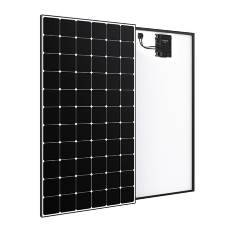
Maxeon SunPower Performance SPR-P6-555-UPP Setup guide

SafetyandInstallationInstructions
UnitedStatesandCanada
ThisdocumentappliestoPerformancemodules
listedinTable1.
Contentsofthismanualaresubjecttochangewithoutnotice.
Forthelatestversionpleaserefertowww.maxeon.com/us/PSeriesInstallGuide
MaxeonSolarTechnologies,Ltd.
www.sunpower.maxeon.com
Document539821Rev.B
ThisdocumentincludesreferencestoPerformanceSeriesmodules.These
modulesdonothavegroundingrestrictionsandallarecompatiblewithhigh‐
efficiencytransformerlessinverters.

MAXEONSOLARTECHNOLOGIES,LTD.
SafetyandInstallationInstructions‐Document539821RevB
©2022MaxeonSolarTechnologies,Ltd.Allrightsreserved.Specificationsincludedintheseinstructionsaresubjecttochangewithoutnotice.Page|2
SafetyandInstallationInstructions
(UnitedStatesandCanada)
1.0 Introduction
TheseinstructionsprovidesafetyandinstallationinstructionsforCSA
ListedMaxeonphotovoltaic(PV)modulesthathavetheCSAlogoonthe
productlabel:
1.1DisclaimerofLiability
Theinstallationtechniques,handling,anduseofthisproductarebeyond
companycontrol.Therefore,Maxeonassumesnoresponsibilityforloss,damage
orexpenseresultingfromimproperinstallation,handling,oruse.
1.2CSAListingInformation
ThisproductmeetsorexceedstherequirementssetforthbyUL61730andUL
61215.TheseStandardscoverflat‐platePVmodulesandpanelsintendedfor
installationonbuildingsorthoseintendedtobefreestanding.Tosatisfythe
Listingforthisproductthemodulesmustbemountedwitharackorstandoff
structure.TheListingdoesnotincludeintegrationintoabuildingsurfacebecause
additionalrequirementsmayapply.Thisproductisnotintendedforusewhere
artificiallyconcentratedsunlightisappliedtothemodule.
1.3LimitedWarranty
ModulelimitedwarrantiesaredescribedinfullintheMaxeonwarranty
certificatesobtainableatwww.sunpower.maxeon.com.Insummary,theLimited
Warrantiesdonotapplytoanyofthefollowing:
PVModulessubjectedto:(i)misuse,abuse,neglectoraccident;(ii)alterationor
improperinstallation(improperinstallationincludes,withoutlimitation,
installationthatdoesnotcomplywithallMaxeoninstallationinstructionsand
operationsandmaintenanceinstructionsofanytype,asmaybeamendedand
updatedfromtimetotimeatMaxeon’ssolediscretion,andallnational,state,
andlocallaws,codes,ordinances,andregulations);(iii)repairormodificationby
someoneotherthananapprovedservicetechnicianofMaxeon;(iv)conditions
exceedingthevoltage,wind,snowload,andanyotheroperational
specifications;(v)powerfailureorsurges;(vi)indirectordirectdamagefrom
lightning,flood,fireorotheractsofnature;(vii)damagefrompersons,biological
activity,orindustrialchemicalexposure;or(viii)damagefromimpactorother
eventsoutsideMaxeon’scontrol..
2.0 SafetyPrecautions
Beforeinstallingthisproduct,readallsafetyinstructionsinthisdocument.
AllinstallationsmustbeperformedincompliancewiththeNationalElectrical
Code(NEC)andanyapplicablelocalcodes.
ForCanadianjurisdictions,installationsshallbeinaccordancewithCSAC22.1,
SafetyStandardforElectricalInstallations,CanadianElectricalCode,Part1
ModulescertifiedtoUL61730areSafetyClass2forprotectionagainst
electricshock
Therearenouser‐serviceablepartswithinthemodule.Donotattemptto
repairanypartofthemodule.
Installationshouldbeperformedonlybyqualifiedpersonnel.
Donotstandon,drop,scratch,orallowobjectstofallonmodulesasdoingso
maydamagethemandvoidthewarranty.
Donotplaceanythingonthemodules,evenforamomentbecauseresulting
residuemaydamageorstaintheglasssurface.
Ifthefrontglassisbroken,orthebacksheetistorn,contactwithanymodule
surfaceormoduleframecancauseelectricshock. Damagedmodulesshould
beimmediatelydisconnectedfromtheelectricsystem.Themoduleshouldbe
removedfromarrayassoonaspossibleandcontactthesupplierfordisposal
instructions.
BrokenJ‐boxesorconnectorsareelectricalhazardsaswellaslaceration
hazards.Installersshouldremoveanysuchmodulefromthearrayand
contactMaxeonfordisposalinstructions.
Donotinstallorhandlethemoduleswhentheyarewetorduringperiodsof
highwind.
Donotblockdrainholesorallowwatertopoolinornearmoduleframes.
Maxeonrecommendsaconservativeminimumcablebendradiusofequalto
orgreaterthan40mm(1.5”).
Unconnectedconnectorsmustalwaysbeprotectedfrompollution(e.gdust,
humidity,foreignparticles,etc),priortoinstallation.Donotleave
unconnected(unprotected)connectorsexposedtotheenvironment.Aclean
assemblyenvironmentisthereforeessentialtoavoidperformance
degradation.
Donotallowtheconnectorstocomeincontactwithchemicalssuchas
greases,oilsandorganicsolventswhichmaycausestresscracking.
Donotdisconnectanymoduleswhenitsinverterisfeedingintothegrid.
Switchofftheinverterbeforedisconnecting,reinstallingormakinganyaction
withthemodules.
Forconnectors,whichareaccessibletountrainedpeople,itisimperativeto
usethelockingconnectorsandsafetyclips,ifapplicable,inordertodefend
againstuntrainedpersonneldisconnectingthemodulesoncetheyhavebeen
installed.
CoverallmodulesinthePVarraywithanopaqueclothormaterialbefore
makingorbreakingelectricalconnections.
Asthemodulesbendundertheload,donotmountsharpobjects(e.g.
screws)nearthemodulebackside.
Donotmountrailsunderthejunctionboxes
Donotattachoradhereitemsatthebacksheetofthemodules.
ContactMaxeonifmaintenanceisnecessary.
Savetheseinstructions!
2.1FireRating
ThemodulefireratingisType29perUL1703,2013edition.Firerating
classificationforanyPVsystemusingUL1703:2013canonlyestablishafirerating
incombinationwiththemountingsystemratingsnormallyfoundinthemounting
systeminstallationinstructions.
3.0 ElectricalCharacteristics
ElectricalcharacteristicsofthemodulesaredescribedinTable1below.Rated
electricalcharacteristicsarewithin10percentofmeasuredvaluesatStandard
TestConditionsof:1000W/m2,25°Ccelltemperatureandsolarspectral
irradianceperIEC60904‐3orirradiationof(airmass)AM1.5global(G)spectrum.
Eachmodulecontainsthreebypassdiodes.Themaximumseriesfuseratingis
25A.
Undernormalconditions,aphotovoltaicmodulemayexperienceconditionsthat
producemorecurrentand/orvoltagethanreportedatStandardTestConditions.
Accordingly,thevaluesofISCandVOCmarkedonULListedmodulesshould
alwaysbemultipliedbyafactorof1.25whendeterminingcomponentvoltage
ratings,conductorcapacities,fusesizesandsizeofcontrolsconnectedtothe
moduleoutput.RefertoSection690‐8oftheNECforanadditional1.25Safety
factorwhichmaybeapplicable.
DANGER!Moduleinterconnectioncablespassdirectcurrent(dc)and
aresourcesofvoltagewhenthemoduleisunderloadandwhenitis
exposedtolight.Directcurrentcanarcacrossgapsandmaycause
injuryordeathifimproperconnectionordisconnectionismade;or
ifcontactismadewithmoduleleadsthatarefrayedortorn.Donot
connectordisconnectmoduleswhenacurrentsourceisenergizing
theconductors.Modulesmaycontainhighvoltagewhen
interconnectedwithothermodules.
IMPORTANT!Pleasereadtheseinstructionsintheirentiretybefore
installing,wiring,orusingthisproductinanyway.Failuretocomply
withtheseinstructionswillinvalidatetheMaxeonLimitedWarranty
forPVModules.

MAXEONSOLARTECHNOLOGIES,LTD.
SafetyandInstallationInstructions‐Document539821RevB
©2022MaxeonSolarTechnologies,Ltd.Allrightsreserved.Specificationsincludedintheseinstructionsaresubjecttochangewithoutnotice.Page|3
Table1:ElectricalCharacteristics1
Module RatedPower
(W)
Voltageat
RatedPower
Vmpp(V)
Currentat
RatedPower,
Impp(A)
OpenCircuit
VoltageVoc
(V)
ShortCircuit
Current,Isc(A)
Maximum
SystemVoltage
ULVmax(V)
SPR‐P6‐555‐UPP 555 40.0 13.89 47.3 14.73 1500
SPR‐P6‐550‐UPP 550 39.7 12.85 47.1 14.68 1500
SPR‐P6‐545‐UPP 545 39.5 13.8 46.9 14.64 1500
SPR‐P6‐540‐UPP 540 39.3 13.76 46.7 14.59 1500
SPR‐P6‐535‐UPP 535 39.0 13.71 46.5 14.54 1500
SPR‐P5‐545‐UPP 545 39.5 13.81 47.8 14.83 1500
SPR‐P5‐540‐UPP 540 39.2 13.78 47.6 14.80 1500
SPR‐P5‐535‐UPP 535 38.9 13.76 47.4 14.79 1500
SPR‐P5‐530‐UPP 530 38.6 13.73 47.1 14.78 1500
SPR‐P5‐525‐UPP 525 38.3 13.71 46.8 14.77 1500
SPR‐P5‐520‐UPP 520 38 13.69 46.6 14.76 1500
4.0 ElectricalConnectionsandSystemMonitoring
Modulesmaybeconnectedinseriesand/orparalleltoachievethedesired
electricaloutputaslongasoptimumdesignparametersareachievedcertain
conditionsaremet.Pleaseuseonlythesametypeofmodulesinacombined
sourcecircuit.Donotmixthemoduleswithdifferentnameplateswithout
authorizationbyMaxeon.
Evenifallowedbylocalregulation,PlugandSocketconnectorsmatedtogetherin
aPVsystemmustbeofthesametype(model,rating)fromthesame
manufactureri.e.aplugconnectorfromonemanufacturerandasocket
connectorfromanothermanufacturer,orviceversa,shallnotbeusedtomakea
connection.
Maxeonrecommendsaconservativeminimumbendingradius(R)5xcable
diametermustbemaintainedandmustnotbebentonthedirectexitofthe
connectororjunctionbox.Avoidexposureofelectricalconnectionstodirect
sunlightanddonotplacetheconnectorinalocationwherewatercouldeasily
accumulate.Installersmustrefertoconnectormanufacturer’sinstructionfor
furtherinstallationandconnectionrequirements.
Connectorsarefactoryassembledwithintentionalgapsbetweenthecablenut
andthebodyoftheconnector.Donotretightenmoduleconnectornutsasthis
mayleadtostresscrackingoftheconnectorassemblyandwillvoidthewarranty.
4.1EquipmentGrounding
Toreducethepossibilityofelectricalshock,groundtheframeofthemoduleor
arrayperNECbeforewiringthecircuit.Inordertoinstallinaccordancewiththeir
CSAListing,Maxeonmodulesmustbegroundedusinggroundinghardwarethat
meetsrequirementsforgroundingsystemsinUL61730andUL61215on
anodizedaluminumframes.Maxeonrecommendstorefertotheapplicable
regionalandlocalcodesandrequirementsongroundingPVarraysandmounting
framesinconjunctionwithyourrackingsupplier.
Inaddition,toavoidcorrosionduetotheuseofdissimilarmetalsMaxeon
recommendsstainlesssteelbetweencopperandaluminum.
4.2SystemGrounding
ReviewTable2belowforthepropergroundingtechniquesfortheinstallationof
yourparticularMaxeonmodules.
4.3SeriesConnection
Themodulesmaybewiredinseriestoproducethedesiredvoltageoutput.Do
notexceedthemaximumsystemvoltageshowninmoduledatasheetsand
productlabel.
1Formodelsnotshownhere,pleasecontactMaxeontechnicalsupportorvisit
www.sunpower.maxeon.com.ElectricalparametersaremeasuredatStandardTest
Conditions(STC).Theseriesfusemusthaveaninterruptingratingthatisequaltoorgreater
thanthemaximumfaultcurrentthatthefuseisrequiredtointerrupt,includingcontributions
fromallconnectedsourcesofenergy.
RefertoNECArticle100,PartIIastowhattypeofseriesfuseisacceptableformodulesrated
athigherthan600Vdcsystemvoltage.
4.4ParallelConnection
Themodulesmaybecombinedinparalleltoproducethedesiredcurrentoutput.
Eachseriesstringormodulemayberequiredtobefusedpriortocombiningwith
otherstringsiftheresultingmaximumfusesizeallowed(numberofmodules
whichcanbeconnectedinparallelandprotectedbyonefuse)exceedsthefuse
ratingasshowninthemoduledatasheetandproductlabel.Pleaserefertothe
NECArticle690foradditionalfusingrequirements.
Table2:ModuleGroundingKey
ModuleModelGroundingKey
MaxeonP‐Seriesmoduleshavenogroundingrestrictions:
AllmodelnumbersstartingwithSPR‐Py‐xxx‐UPP
IMPORTANT!P‐Seriescanbegroundedwitheitherpolarity.Failureto
complywiththisrequirementwillreducesystemperformanceand
invalidateMaxeon’sLimitedPowerWarrantyforPVModules.
5.0 ModuleMounting
TheMaxeonLimitedWarrantyforPVModulesiscontingentuponmodulesbeing
mountedinaccordancewiththerequirementsdescribedinthissection.
5.1SiteConsiderations
Maxeonmodulesshouldonlybemountedinlocationsthatmeetthefollowing
requirements:
OperatingTemperature:AllMaxeonmodulesmustonlybemountedin
environmentsthatensuretheywilloperatewithinthefollowingtemperatures:
OperatingTemperaturerange(ambient)‐40°Cto+85°C
‐40°Fto+185°F
Adequateventilationshouldbeprovidedbehindorunderneaththemodules,
especiallyinhotenvironments.
Shading:Modulesshouldbeinstalledsothatpermanentshadingofcellsis
avoidedandpartialshadingthatmayoccurduringcertaintimesofthedayor
yearisminimized. Permanentshadingisdefinedasshadethatiscastoverthe
sameposition(ofconstantarea)ofthesolarmodulethroughoutthegeneration
hoursoftheday.
Shadingmayinduceincertaincasesstrongenergyproductionreduction,evenin
caseofsmallshadingandshouldbeavoidasmuchaspossible,especiallyatmid‐
daywhentheproductionismaximum.
DesignStrength:Maxeonmodulesaredesignedtomeetapositive(downward)
and/ornegative(upward)withstandingtestpressurewhenmountedasperthe
guidelinesinSection5.2andconfigurationsinAppendix.Testloadsarefor
informationpurposesonly;designloadsshouldbeconsideredfortheproject
design.
Whenmountingmodulesinsnowproneorhighwindenvironments,specialcare
shouldbetakentomountthemodulesinamannerthatprovidessufficient
designstrengthwhilemeetinglocalcoderequirements.
ExcludedOperatingEnvironments
CertainoperatingenvironmentsarenotrecommendedforMaxeonmodules,and
areexcludedfromtheMaxeonLimitedWarranty.
Modulesaredesignedforamaximumaltitudeof2000m.
NoMaxeonmoduleshouldbemountedatasitewhereitmaybesubjectto
directcontactwithsaltwater,orotheraggressiveenvironment.
Modulesshouldnotbeinstallednearflammableliquids,gases,orlocationswith
hazardousmaterials;ormovingvehiclesofanytype.
PerformanceSeriesMountingOrientation
CommercialPerformanceSeries(P‐Series)modulesaredesignedtoperform
betterifinstalledinlandscapeorientation.Inlandscapeorientation,P‐series
modulesmaintainhigherpowerinconditionsofrow‐to‐rowshadingand/oredge
soiling.

MAXEONSOLARTECHNOLOGIES,LTD.
SafetyandInstallationInstructions‐Document539821RevB
©2022MaxeonSolarTechnologies,Ltd.Allrightsreserved.Specificationsincludedintheseinstructionsaresubjecttochangewithoutnotice.Page|4
5.2MountingConfigurations
Modulesintegratedintoormountedoveraroofingsystemmustbemounted
overafire‐resistantroofcoveringratedfortheapplication.Modulesmaybe
mountedatanyangle,fromhorizontaltovertical.Toreducesoiling,modules
shouldbemountedataminimumof5degrees.
Specificinformationonmoduledimensionsandthelocationofmountingand
groundingholesisprovidedinAppendix.Thesysteminstallerisresponsiblefor
thedeterminationoflocation‐specificloadrequirements.
ItshouldbenotedthatwatertightnessisnotensuredbyMaxeon,therefore,if
watermanagementisrequired,themountingsystemshouldbedesigned
accordingly.
ThemoduleisonlyCSAListedforusewhenitsfactoryframeisfullyintact.Do
notremoveoralterthemoduleframe,anddonotcreateadditionalmounting
holesbecausedoingsomaycompromisetheintegrityoftheframe.
Modulesmaybemountedusingthefollowingmethodsonly:
1) FrameHoles:Securethemoduletothestructureusingthefactory
mountingholes.Four1/4″stainlesssteelbolts,withnuts,washers,andlock
washersarerecommendedpermodule;tightenedtoamin.torqueof10in‐
lb.Thismethodhasbeencertifiedbyathird‐partyorganizationaccordingto
UL1703.Forframeholemounting,modulesmustbesecuredusingthe
holesshowninAppendix.
2) Clamps:Mountthemodulewiththeoppositeclampsonthelongerand/or
shortersidesofthemodule.Installersshouldensuretheclampsareof
sufficientstrengthtoallowforthemaximumdesignpressureofthe
module.ClampsarenotprovidedbyMaxeon.Clampsthatsecuretothetop
oftheframemustnotdeformthetopflange.Clampsmustapplyforce
collinearwiththe‘wall’ofthe
moduleframeandnotonlytothe
topflange.Clampsorinstallation
proceduresthatputexcessive
forceonthetopflangewill
deformtheframe,voidthe
modulewarrantyandriskglass
breakage.Figure1aillustrates
locationsfortopframeclamp
force.Whenclampingtothe
moduleframe,torqueshouldneverexceed132in‐lbs(15Nm)toreduce
chancesofframedeformationand/orglassbreakage.Iftheclamp
manufacturerrecommendsaspecifictorquevaluewhichislowerthan132
in‐lbs(15Nm),theinstallershouldusetheclampmanufacturer’storque
value.Iftheclampmanufacturerrecommendsaspecifictorquevalue
whichishigherthan132in‐lbs(15Nm),theinstallershouldcontactthe
clampmanufacturerforacceptanceofthe132in‐lbs(15Nm)maximum
torquevalueortofindalternativeclamps.Acalibratedtorquewrenchmust
beused.Mountingsystemsshouldbeevaluatedforcompatibilitybefore
installingspeciallywhenthesystemisnotusingClamps.
Minimumclampwidthallowanceis≥35mm,andforcornerclampingthe
minimumclampwidthis:≥50mm.Clampsshouldnotbeincontactwiththe
frontglassandclampsshouldnotdeformtheframe.
Clampswithgroundingfeaturessuchasteeth,pinsthatpenetratethe
ionizationoftheframeareknowntodeformtheframeandbreakthe
moduleglass.Alltheclampswithgroundingfeaturesshouldbeusedatthe
installer/customer’sownrisk.
5.3GroundMountApplicationsforBifacialmodules
Variousenvironmentalandinstallationparametersaffectbifacialgain.Albedoisa
measureoftheamountoflightreflectedfromthegroundsurface.Ahigher
albedofactorwillincreaseirradianceonthebacksideandresultinhigherbifacial
gainofthemodule.Thesurfaceconditions,monthoftheyear,timeofday,GHI
andDNIbothinfluencetheamountofincidentrearsideirradiance.
Maxeonrecommendstocheckwithsolarmodulemountinghardwaresupplierin
ordertodeterminetheStructureShadingfactorofyourparticularinstallation.
TheStructureShadingFactorvarieswithrackingsystemdesign,irradiance,
albedoandheightofmoduleinstallationabovegroundandhasanoverallimpact
ontherearsideirradiancemismatch.
TheRearsidemismatchlossesareproportionaltothealbedo,heightofthe
modulesabovegroundandstructureshadingfactor.Theirradiancenon‐
uniformityontherearsideresultsinmismatchgenerallyasthealbedoincreases
andinstallationheightofthemodulesarelowertotheground.
5.4RooftopApplicationsforBifacialmodules
Bifacialmodulesusedirect,reflectedordiffusesunlightattherearsideto
generateadditionalpower.Therefore,itisrecommendedtousebifacialmodules
installedonflatroofapplications.
Inordertomaximizethebifacialgainattherooftopapplicationsthefollowing
parameterslistedbelowshouldbeconsidered:
SurfaceAlbedo
RoofIntegrity
ModuleTiltAngle
ModuleElevation
StructuralBacksideShading
Thebifacialmodulescanbemountedbothlandscapeorportraitorientationas
showninAppendixsection.
Wheninstallingabifacialmoduleonaroof,ensurethattheroofconstructionand
thestructuralloadcalculationsofthebuildingaresuitable.
Bifacialgaintendstobemosteffectivewithahighertiltangle.
Asthetiltangleandthemoduleelevationfromtheunderlyingsurfaceincreases,
morereflectedlightanddiffuselightcanbecapturedbythemodule.
Themountingrailsshallbedesignedtolimittherearsideshadingasmuchas
possible.
5.5BifacialElectricalConsiderations
Theoverallelectricalbifacialgainisdeterminedbythecombinationofsurface
albedo,irradiance,moduletiltangle,shadinglossesfromtherearside,rearside
mismatchandmoduleelevationaboveground.PleaserefertotheMaxeon
datasheetfortheelectricaloutputswithrespecttotheoverallbifacialgain.
Pleaseutilizeasuitableperformancesoftwarepackagetosimulatetheoverall
bifacialgain
5.6HandlingofModulesduringInstallation
Donotplacemodulesfaceforwardindirectcontactwithabrasivesurfaceslike
roofs,driveways,woodenpallets,railings,stuccowalls,etc…
Themodulefrontsurfaceglassissensitivetooilsandabrasivesurfaces,which
mayleadtoscratchesandirregularsoiling.
Duringstorage,modulesneedtobeprotectedfromrainoranykindsofliquids.
Requiredstoragetemperatureisbetween10°Cto40°Cinadryenvironment
(humiditybetween30to80%).Donotstoremodulesoutdoortoavoidmoisture
andwetconditions.
Modulesthatfeatureantireflectivecoatedglassarepronetovisiblefingerprint
marksiftouchedonthefrontglasssurface.Maxeonrecommendshanding
moduleswithanti‐reflectiveglasswithgloves(noleathergloves)orlimiting
touchingofthefrontsurface.Anyfingerprintmarksresultingfrominstallation
willnaturallydisappearovertimeorcanbereducedbyfollowingthewashing
guidelinesinSection6.0below.Anymodulecoverage(coloredplastictarpsor
similar)duringinstallationcanleadtopermanentfrontglassdiscolorationandis
notrecommended.Theuseofvacuumliftingpadscancausepermanentmarks
onthefrontglass.Neverliftormovethemoduleusingthecablesorthejunction
boxunderany‐circumstances.
Systemenergizationandshutdownproceduresneedtobefollowedbasedon
respectiveNationalguidelinesandlocalregulations.Safesiteoperational
practicesmustbeadheredbeforeenergizingthePVsystem(e.g.electrical
continuity,avoidingdirectcontactwithelectrical/framingequipment,wearing
safetyPPE,etc.).Systemshouldbeelectricallydisconnectedduringmaintenance,
upgrades,andmodificationworkswhichcanaffecttheoperationofPVsystem.
6.0MaintenanceandCleaning
TrainedMaxeondealerortrainedMaxeonsupportpersonnelshouldinspectall
modulesannuallyforsafeelectricalconnections,soundmechanicalconnections,
andfreedomfromcorrosion.
Periodiccleaningofmoduleglasshasresultedinimprovedperformancelevels,
especiallyinregionswithlowlevelsofannualprecipitation;thereforeMaxeon
recommendsperiodiccleaningofthemodules.
Tocleanamodule,washitsglasssurfacewithpotable,non‐heatedwater.
NormalwaterpressureisadequatewhencleaningtheARglass.Some
Forcemustnotdeform
topframeflangeor
glassmaybreak
Figure1a:ClampForceLocations
Forcecan
beapplied
inlinewith
framewall

MAXEONSOLARTECHNOLOGIES,LTD.
SafetyandInstallationInstructions‐Document539821RevB
©2022MaxeonSolarTechnologies,Ltd.Allrightsreserved.Specificationsincludedintheseinstructionsaresubjecttochangewithoutnotice.Page|5
fingerprints,stains,oraccumulationsofdirtontheglassmayberemovedwith
over‐the‐counterglasscleaners(suchasWindex®orequivalent),orwitha3%
soap‐and‐watersolution.Forsmallersystems,wetthemoduleglasswiththe
solution,letitstandforfiveminutes,andthenwetthemagainanduseasoft
spongeorseamlessclothtowipetheglasssurfaceinacircularmotion.Forlarge
systems,wetthemoduleswiththecleaningsolution,letthemstandforfive
minutes,andthenrinsethemwithhigh‐pressurewaterorasoftsqueegee.Do
notuseharshindustrial‐strengthcleaningmaterialssuchasscouringpowder,
steelwool,scrapers,blades,orothersharpinstrumentstocleanthemodule
glass.Useofsuchmaterialswillvoidtheproductwarranty.
RecommendedCableManagement
Performance Product Line:
Portrait Stringing
Landscape Stringing
Leapfrog Stringing (Portrait)
*Theimagesaresolelyforillustrationpurposesonly.

MAXEONSOLARTECHNOLOGIES,LTD.
SafetyandInstallationInstructions‐Document539821RevB
©2022MaxeonSolarTechnologies,Ltd.Allrightsreserved.Specificationsincludedintheseinstructionsaresubjecttochangewithoutnotice.Page|6
Appendix:MountingLoadsandConfigurations
GEN 4.3 FRAME PROFILE
A - SLOT Holes (8X 14mm (L) x 9mm (W), R3.5mm)
B - Mounng Holes (4X 10mm (L) x 7mm (W), R6.8mm)
C - Ground Holes (4X Ø 4.2mm)
SunPower Performance 5/6 Bifacial Solar Panel
(SPR-P5-XXX-UPP, SPR-P6-XXX-UPP)
1092 mm [42.99in]
1043 mm [41.06]
400 mm
[15.74in]
1100 mm [43.31in]
1400 mm [55.12in]
2384 mm [93.86in]
0
646
[25.43]
0
AB
C
SIDE FRAME PROFILE END FRAME PROFILE
1088.77 [42.86in]
546
[21.49]
1232.77 [48.53in]
1042
[41.02] 1042
[41.02] 646
[25.43]
546
[21.49]
323
[12.72]
0
323
[12.72]
35mm [1.38]
35mm [1.38]
35 mm [1.38]
16 mm
[0.630]
0
Mounng
Configuraon
Descripon
Mounng Configuraon Diagram
Front View Back View
Mounng Zone
Locaons
(distance from corner
in mm)
546 - 646
Design Load
Long Side Mounng,
Rails Perpedincular to
Mounng Frame
Long Side Mounng,
Rails Parallel to
Mounng Frame
Short Side Mounng,
Point Supported
(End Mount)
Short Side Mounng,
Rails Parallel to
Mounng Frame
(End Mount)
646 - 1042
50 - 546
0 - 323
0 - 323
Test Lo ad
+1400/-1400
+2400/-1200
+2400/-2000
+5400/-2400
+933/-933
+1600/-800
+1600/-1333
+3600/-1600
TOP CLAMPS
Short Side Mounng,
Point Supported
with Rail
(End Mount)
0 - 323
2 Test loads are for informaon purposes only, design loads should be considered for the project design.
50 - 546 +2400/-1200 +1600/-800
+3600/-2400
+1400/-1400
+2400/-1600
+933/-933
Downward/Upward
(Pa)
Downward/Upward
(Pa)
Long Side Mounng,
Point Supported
50 - 100 +1800/-1800 +1200/-1200
546 - 646 +3000/-2400 +2000/-1600
Design Load considers 1.5 Factor of Safety, Test load = Design load x 1.5. Product Warranty covers only design
load values. The design loads listed in this table supersede all other loads that may be defined by other
pares, unless there is a formal authorizaon by Maxeon.
Mounng
Configuraon
Descripon
Mounng Configuraon Diagram
Front View Back View
Mounng Zone
Locaons
(distance from corner
in mm)
1400mm Holes
Design Load
Long Side Mounng,
Rails Perpedincular to
Mounng Frame 1100mm Holes
400mm Holes
Test Lo ad
+1800/-1800
+2400/-2000
+5400/-2400
+5400/-2400
+1200/-1200
+1600/-1333
+3600/-1600
+3600/-1600
400mm Holes
BOLTS
Center Mounng
(1x Portrait Tracker)
3 Minimum of 24mm in diameter washer size is required.
Downward/Upward
(Pa)
Downward/Upward
(Pa)
4 Rails must not be under the juncon box.
Measurement Tolerances are +/-3 mm for the Length and Width of the Module.
This manual suits for next models
10
Table of contents
Other Maxeon Solar Panel manuals
Popular Solar Panel manuals by other brands

Heckert Solar
Heckert Solar NeMo P Standard Installation and operating instructions

Generark
Generark SolarPower ONE user guide

Regulus
Regulus KPC1 BP Installation and operation manual

Snapper
Snapper 1690503 Operator's manual

Nature Power
Nature Power SYK120-18MF instruction manual

Renogy
Renogy E-flex 14W quick start guide

Donaldson Torit
Donaldson Torit E-100 Installation and operation manual

Jinergy
Jinergy JNMP60 series installation guide

MSW
MSW S-POWER SYSTEM LIS 3000 PRO user manual

Kyocera
Kyocera KC-TYPE installation manual

Astronergy
Astronergy CHSM6610M installation manual

Restar solar
Restar solar RT Series installation manual