Jayu JY360M6-Aa-5 User manual

Xuzhou Jiayu Solar Energy Technology Co.,Ltd.
North of Peigong Road, East of Hankang Road, Peixian Economic,Development Zone, Xuzhou City, Jiangsu Province, 221000, P.R. China
Website: www.jayusolar.com Email: ranfeng@jayusolar.com Tel: +86 13151232006
Installation Manual
GENERAL INFORMATION
Installing solar photovoltaic systems requires specialized skills and knowledge. The installer assumes all risk
of injury, including risk of electric shock. Module installation should be performed only by a qualified installer.
All modules come with a permanently attached junction box and 4mm²wire. Jayu Solar can provide
customers with fitted cables for ease of installation, if desired.
When disconnecting wires connected to a photovoltaic module that is exposed to sunlight, an electric arc
may occur. Arcs can cause burns, start fires or otherwise create safety problems. Exercise caution when
disconnecting wiring on modules exposed to sunlight.
Photovoltaic solar modules convert light energy to direct-current electrical energy, and are designed for
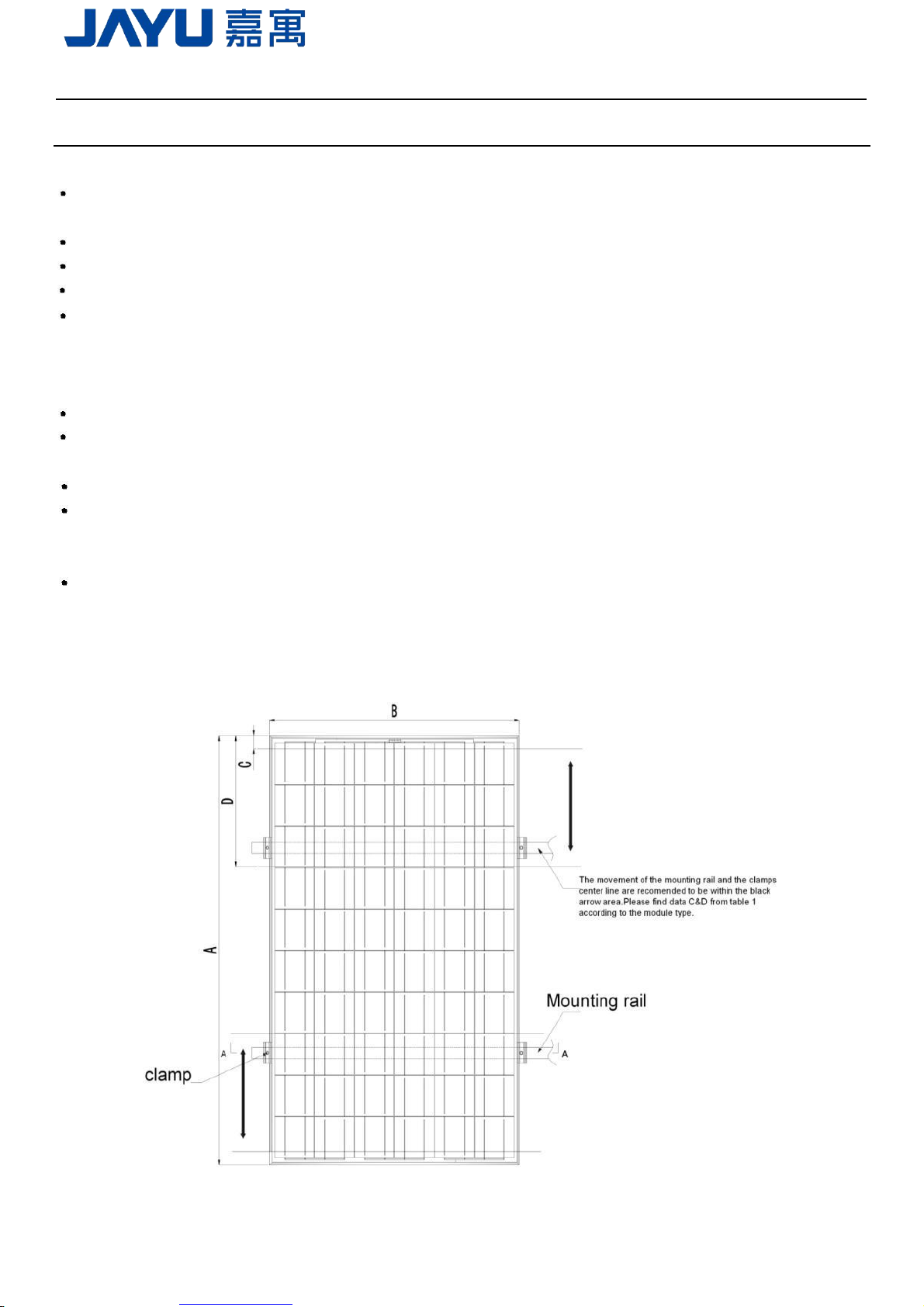
outdoor use. Proper design of support structures is the responsibility of the system designer and installer.
Do not attempt to disassemble the module, and do not remove any attached nameplate
or components. Doing so will void the warranty.
Do not use mirrors or other hardware to artificially concentrate sunlight on the module.
Safety precautions for installing a solar photovoltaic system
Solar modules produce electrical energy when light shines on the front surface. The DC voltage may exceed 30V.
If modules are connected in series, the total voltage is equal to the sum of the individual module voltages. If
modules are connected in parallel, the total current is equal to the sum of individual module current
Keep children well away from the system while transporting and installing mechanical and electrical
components.
Completely cover the module with an opaque material during installation to keep electricity from being
generated.
Abide with the safety regulations for all other components used in the system, including wiring and cables,
connectors, charging regulators, inverters, storage batteries and rechargeable batteries, etc.
Use only equipment, connectors, wiring and support frames suitable for use in a solar electric systems.
Always use the same type of module within a particular photovoltaic system.
Modules rated for use in this application class may be used in systems operating at greater than 50V DC or
240W, where general contact access is anticipated. Modules qualified for safety through this part of
IEC61730 and IEC61730-2 and within this application class are considered to meet the requirements for
safety classⅡ. Under normal conditions, a photovoltaic module is likely to experience conditions that
produce more current and/or voltage than reported at standard test conditions. Accordingly, the value of Isc
and Voc marked on this module should be multiplied by of 1.25 when determining component voltage ratings,
conductor current ratings, fuse sizes, and size of controls connected to the PV output.
The recommend maximum series fuse is 15A(156 module).
The modules have been evaluated for a maximum positive loading of 5400pa.
Do not wear metallic rings, watchbands, ear, nose, or lip rings, or other metallic devices
while installing or troubleshooting a photovoltaic systems.
Be sure to use appropriate safety equipment (insulated tools, insulated gloves, etc) approved
for use in electrical installations.
Application class A: meet the requirements for safety class II.
1/13

Xuzhou Jiayu Solar Energy Technology Co.,Ltd.
North of Peigong Road, East of Hankang Road, Peixian Economic,Development Zone, Xuzhou City, Jiangsu Province, 221000, P.R. China
Website: www.jayusolar.com Email: ranfeng@jayusolar.com Tel: +86 13151232006
Installation Manual
MECHANICAL INSTALLATION
Selecting the location
Select a suitable location for installation of the module.
The module should be face sun, reduce loss from exterior sunshine and raise export power.
Detailed information on optimal module orientation will depend on the sunlight and specific system design.
For the optimal annual output from the solar module, we suggest the mounting angle be equal to the latitude
of the city where the modules are being installed. For the optimal battery performance in winter months, we
suggest the mounting angle be 10 degrees greater than the latitude of the city where the installation is being
done. For optimal solar battery performance in all four seasons,we suggest the mounting angle be 10
degrees less than latitude of the city where the installation is being done.
A mounting location should be chosen where the module will not be shaded at any time of the day.
Do not install the module near other equipment or in locations where flammable gases can be generated or
collected.
The fire rating of this module is valid only when mounted in the manner specified in the mechanical mounting
instructions.
Modules can not be used in other excessive and harsh environments, such as hail, snow, sand, smoke, air
pollution, soot, flammable gases, near open flames, and highly corrosive substances (salt, salt spray, salt
water, acid rain) , As this will affect the module's safety and performance. If the installation environment is
special, such as the seaside, farm, high humidity or wind and other large environment, please consult your
local dealer for professional support and confirmation. If you need to be installed at a high altitude, the
altitude should not exceed 2000m.
Selecting the Proper Mounting Structure and Hardware
1.Mounting Structure
(1)Screw fitting:
Observe all instructions and safety precautions included with the mounting system to be used with the
module.
The aluminous frame has eight (8) mounting holes, and two (2) holes for grounding.
Do not drill holes in the glass surface of the module. Doing so will void the warranty.
Do not drill additional mounting holes in the module frame. Doing so will void the warranty.
Modules must be securely attached to the mounting structure (racking) using eight (8) mounting points for
normal installation. If heavy wind or snow loads are anticipated, we require advance notification. Load
calculations are the responsibility of the system designer or installer.
The support module mounting structure must be made of durable, anticorrosion and UV-resistant material.
Hardware
The size of fixing hole for common modules is 9*14 and the size of the fixing nut is M8. The size of fixing hole
for common modules is 7*12 and the size of the fixing nut is M6.Drawings as follows.
2 / 13

Xuzhou Jiayu Solar Energy Technology Co.,Ltd.
North of Peigong Road, East of Hankang Road, Peixian Economic,Development Zone, Xuzhou City, Jiangsu Province, 221000, P.R. China
Website: www.jayusolar.com Email: ranfeng@jayusolar.com Tel: +86 13151232006
Installation Manual
Figure1: Jayu Solar Module installed with screw fitting method
3 / 13
Chart 1
Mono&Poly-silicon module mechanical drawing
Module type
Cell quantity
Dimensions(mm)
A*B
C
D
E
F
H
I
6*12
1956*992
50
942
1676
1176
M8
35
6*12
1956*992
40
949
1676
1176
M6
28
6*10
1650*992
35\40\50
942
1370
870
M8
35
6*10
1650*992
40
949
1370
870
M6
28
6*10
1640*992
35\40\50
942
1360
860
M8
35
156 Mono \Poly -silicon
6*10
1640*992
40
949
1360
860
M6
28
White
6*10
1636*992
35\40\50
942
1356
856
M8
35
6*10
1636*992
40
949
1356
856
M6
28
6*9
1482*992
35\40
942
1202
702
M8
35
6*9
1482*992
40
949
1202
702
M6
28
6*8
1325*992
35\40
942
1045
545
M8
35
6*8
1325*992
40
949
1045
545
M6
28
Table 1 The key size for each type of modules

Xuzhou Jiayu Solar Energy Technology Co.,Ltd.
North of Peigong Road, East of Hankang Road, Peixian Economic,Development Zone, Xuzhou City, Jiangsu Province, 221000, P.R. China
Website: www.jayusolar.com Email: ranfeng@jayusolar.com Tel: +86 13151232006
Installation Manual
Module can be mounted on a horizontal or an inclined plane. We recommend type “M8” stainless steel
screws fix up on the bracket which we already fix up.
Insert screw into flat gasket, insert screw into installation hole both on the modules and supporting frame.
Insert screw into flat gasket and spring gasket, then apply nut on the screw and tighten securely.
All bolts, nuts, washers are stainless-steel.
Caution: Guard against contact between different metals. Doing so will give rise to electrochemical corrosion.
(2)Clamp fitting:
Use a certain number of clamps to fix the modules on the mounting rail.
The module clamps should not come into contact with the front glass and must not deform the frame. Be sure
to avoid shadowing effects from the module clamps.
The module frame is not to be modified under any circumstances.
When choosing this type of clamp-mounting method, please be sure to use at least four clamps on each
module, two clamps should be attached on the long sides of the module. Depending on the local wind
and snow loads, additional clamps may be required to ensure the module can bear the load. The applied
torque should be about 8 Newton-meters.
Figure2: PV module installed at portrait orientation with Clamp fitting method
4/13

Xuzhou Jiayu Solar Energy Technology Co.,Ltd.
North of Peigong Road, East of Hankang Road, Peixian Economic,Development Zone, Xuzhou City, Jiangsu Province, 221000, P.R. China
Website: www.jayusolar.com Email: ranfeng@jayusolar.com Tel: +86 13151232006
Installation Manual
Chart 2
The Guide for Fixing Modules
Module type
Module
Cell
Dimensions(mm)
quantity
A*B
C
D
E
F
G
H
JYXXXM6-Aa-5
6*12
1956*992
50
490
11
14
0.5~2
2.5~3
156 Mono-silicon
JYXXXM6-Ab-5
6*10
1640*992
50
428
11
14
0.5~2
2.5~3
White
JYXXXM6-Ac-5
6*9
1482*992
50
396
11
14
0.5~2
2.5~3
JYXXXM6-Ad-5
6*8
1325*992
50
365
11
14
0.5~2
2.5~3
JYXXXP6-Aa-5
6*12
1956*992
50
490
11
14
0.5~2
2.5~3
JYXXXP6- Ab-5
6*10
1636*992
50
427
11
14
0.5~2
2.5~3
156 Poly-silicon
JYXXXP6- Ab-5
6*10
1640*992
50
428
11
14
0.5~2
2.5~3
White
JYXXXP6- Ab-5
6*10
1650*992
50
430
11
14
0.5~2
2.5~3
JYXXXP6- Ac-5
6*9
1482*992
50
396
11
14
0.5~2
2.5~3
JYXXXP6- Ad-5
6*8
1325*992
50
365
11
14
0.5~2
2.5~3
Table 2: Mechanical dimensions when modules installed at portrait orientation with Clamp fitting method
Notes: -PV 60 cells module is used here as an example.
-Dimension “G” represents the distance between clamp and frame.
-Dimension “H” represents the thickness of clamp.
Hardware
Modules can be mounted on a horizontal or an inclined plane. We can use clamps to fix the modules on
the aluminum rails which we set up already.
5 / 13

Xuzhou Jiayu Solar Energy Technology Co.,Ltd.
North of Peigong Road, East of Hankang Road, Peixian Economic,Development Zone, Xuzhou City, Jiangsu Province, 221000, P.R. China
Website: www.jayusolar.com Email: ranfeng@jayusolar.com Tel: +86 13151232006
Installation Manual
According to installation position as shown in table2,put PV modules on the aluminum rails.
Press clamps into the groove of aluminum rails. To ensure clamps is stuck. Use a mid-clamp connect
2 modules as shown in figure 2.Use an end-clamp to fix the edge module as shown in figure 1. Use
hexagon screwdriver to tighten the clamp on the rail securely.
All clamps(include bolts and flange nuts)are stainless-steel.
(1)end-clamp (2)mid-clamp
2. Mounting Methods
Ground Mount
Select the height of the mounting system that prevents the lowest edge of the modules from being covered
by snow for an extended period of time in the winter months in areas that experience heavy snowfall. In
addition, assure that the lowest portion of the module is placed high enough so that it is not shaded by plants
or trees, or will not be damaged by sand or stone driven by wind.
6/13

Xuzhou Jiayu Solar Energy Technology Co.,Ltd.
North of Peigong Road, East of Hankang Road, Peixian Economic,Development Zone, Xuzhou City, Jiangsu Province, 221000, P.R. China
Website: www.jayusolar.com Email: ranfeng@jayusolar.com Tel: +86 13151232006
Installation Manual
Roof Mount
When installing a module on a roof top or building, ensure that it is securely fastened and cannot fall as a
result of wind or snow loads.
Provide adequate ventilation under a module for cooling. A minimum air gap of 93mm is recommended
between the modules and mounting surface.
When installing module on a roof top, ensure that the roof construction is suitable. In addition, any roof
penetration required to mount the module must be properly sealed to prevent leaks. In some cases, a special
support frame may be necessary.
Module could be used in Fire safety Class C. To maintain the corresponding fire prevention level, the tilt
angle should be no less than 5 in/ft (127 mm/305 mm) when the modules are mounted on the roof.
When installing the module on a roof or building, do so in calm winds. Installing a module during strong winds
may cause accidents.
Pole mount
When installing a module on a pole, choose a pole and module mounting structure that will withstand
anticipated winds for the area.
3. General installation notes
Drainage holes must not be covered with any part of the mounting system. The junction box has a breather
port which must be mounted facing downward and cannot be exposed to the rain. The junction box should be
on the highest side of the module when it is mounted in order to orient the breather port correctly. Do not lift
the module by grasping the module's junction box or electrical leads.
7/13

Xuzhou Jiayu Solar Energy Technology Co.,Ltd.
North of Peigong Road, East of Hankang Road, Peixian Economic,Development Zone, Xuzhou City, Jiangsu Province, 221000, P.R. China
Website: www.jayusolar.com Email: ranfeng@jayusolar.com Tel: +86 13151232006
Installation Manual
Do not stand or step on module.
Do not drop the module or allow objects to fall on the module.
Do not place any heavy objects on the module.
Inappropriate transport and installation may damage the module glass or frame.
ELECTRICAL INSTALLATION
Grounding
There are ground holes and marking along either edge of the frame.
All module frames must be properly grounded.
The grounding wire must be properly fastened to the module frame to assure good electrical contact. Use the
recommended type, or an equivalent, connector for this wire.
If the support frame is made of metal, the surface of the frame must be electroplated and have excellent
conductivity.
We recommend the TYCO grounding clip (Manufacturer: Tyco Electronics (Shanghai) Co., Ltd Type
no.:1954381-2,).
When using grounding clips, the grounding conductor should be inserted into the aluminum frame as shown
above in Figure 2, and secured using the 8-32 set screw. Then use a nut (included with the Tyco grounding
clip) to secure the entire assembly, as shown.
Next, insert the 12-10 AWG solid ,un-insulated ground wire into the slot of the lug (see the picture), and
screw down the slotted screw.
Recommended torque of 8-32 screw assembly is 4N.M.
Further, buildup of hardware for mounting the grounding lugs are the same.
General Electrical Installation
Do not use modules of different electrical configurations or manufacturers in the same system.
This module is supplied with MC connectors(PV-KST4、PV-KBT4) or others meet the TUV requirements for
electrical connections.
Refer to Section 690.31 of the NEC to determine appropriate types and temperature ratings of conductors.
Wiring should be #12 AWG, 4 mm2(minimum) and must be temperature rated at 90°C (minimum).
Completely cover system modules with an opaque material to prevent electricity from being generated while
disconnecting conductors.
The cross section area of cable and the capacity of connector must be selected to suit the maximum system
8/13

Xuzhou Jiayu Solar Energy Technology Co.,Ltd.
North of Peigong Road, East of Hankang Road, Peixian Economic,Development Zone, Xuzhou City, Jiangsu Province, 221000, P.R. China
Website: www.jayusolar.com Email: ranfeng@jayusolar.com Tel: +86 13151232006
Installation Manual
short circuit current, otherwise the cable and connector will overheat under large current. Refer to NEC for
details.
For best performance, ensure that positive and negative DC wires run closely together avoiding loops.
The manufacturer of the Bypass Diode is Panjit Group, the model of that is 20SQ045, the Maximum
Recurrent Peak Reverse Voltage is 45V and Maximum Average Forward Current is 20A.
Caution: Electrical shock hazard! Do not touch bare conductors or other potentially energized parts.
MAINTENANCE
Jayu Solar recommends the following maintenance items to ensure optimum performance of the module:
Clean the glass surface of the module as necessary. Use water and a soft sponge or cloth for cleaning. A
mild, non-abrasive cleaning agent can be used if necessary. Do not use dishwasher detergent.
Electrical and mechanical connections should be checked periodically by qualified personnel to verify that
they are clean, secure and undamaged.
Check the electrical and mechanical connections periodically to verify that they are clean, secure and
undamaged.
Problems should only be investigated by qualified personnel.
Observe the maintenance instructions for all other components used in the system.
SHUTTING DOWN THE SYSTEM
Completely cover system modules with an opaque material to prevent electricity from being generated while
disconnecting conductors.
Disconnect system from all power sources in accordance with instructions for all other components used in
the system.
The system should now be out of operation and can be dismantled. In doing so, observe the all safety
instructions as applicable to installation.
PRODUCT INFORMATION
Each module has the following product identification:
Label: Refer to IEC standards
Pass: QC Department detailed inspection date and lot tracking information.
Bar code: Each individual module has a unique serial number.
Example:
Do not remove any label. If the label is removed,
the product warranty will no longer be honored by
Jayu.
Typical serial number barcode lable
9/13

Xuzhou Jiayu Solar Energy Technology Co.,Ltd.
North of Peigong Road, East of Hankang Road, Peixian Economic,Development Zone, Xuzhou City, Jiangsu Province, 221000, P.R. China
Installation Manual
DISCLAIMER OF LIABILITY
Because the use of this manual and the conditions or methods of installation, operation, use and maintenance of
photovoltaic (PV) product are beyond Jayu Solar’s control, Jayu Solar does not accept responsibility and expressly
disclaims liability for loss, damage, or expense arising out of or in any way connected with such installation,
operation, use or maintenance.
No responsibility is assumed by Jayu Solar for any infringement of patents or other rights of third parties,
which may result from use of the PV product. No license is granted by implication or otherwise under any
patent or patent rights.
The information in this manual is based on Jayu Solar’s knowledge and experience and is believed to be
reliable; but such information including product specifications (without limitations) and suggestions do not
constitute a warranty, expresses or implied.
Jayu Solar Solar reserves the right to change the manual, the PV product, the specifications, or product
information sheets without prior notice.
10/13

Xuzhou Jiayu Solar Energy Technology Co.,Ltd.
North of Peigong Road, East of Hankang Road, Peixian Economic,Development Zone, Xuzhou City, Jiangsu Province, 221000, P.R. China
Cell size
(mm)
Model
Voc
(V)
Isc
(A)
Umpp
(V)
Impp
(A)
Pmpp
(W)
Eff
(%)
156*156/
156.75*156.75
JY360M6-Aa-5
47.89
9.66
39.96
9.02
360.00
18.55
JY355M6-Aa-5
47.68
9.49
39.66
8.95
355.00
18.30
JY350M6-Aa-5
47.45
9.40
39.36
8.89
350.00
18.04
JY345M6-Aa-5
47.31
9.31
38.96
8.84
345.00
17.78
JY340M6-Aa-5
47.03
9.27
38.79
8.76
340.00
17.52
JY335M6-Aa-5
46.81
9.22
38.61
8.69
335.00
17.26
JY330M6-Aa-5
46.46
9.15
38.45
8.60
330.00
17.01
JY325M6-Aa-5
46.38
9.09
38.32
8.49
325.00
16.75
JY320M6-Aa-5
46.11
8.92
38.23
8.38
320.00
16.49
JY300M6-Ab-5
40.58
9.42
33.37
8.99
300.00
18.44
JY295M6-Ab-5
40.22
9.33
32.98
8.93
295.00
18.13
JY290M6-Ab-5
39.90
9.30
32.64
8.87
290.00
17.83
JY285M6-Ab-5
39.86
9.21
32.57
8.75
285.00
17.52
JY280M6-Ab-5
39.56
9.09
32.42
8.62
280.00
17.21
JY275M6-Ab-5
38.89
9.04
32.20
8.55
275.00
16.90
JY270M6-Ab-5
38.72
8.89
32.02
8.42
270.00
16.60
JY265M6-Ab-5
38.45
8.79
31.56
8.40
265.00
16.29
JY270M6-Ac-5
36.43
9.62
30.26
8.94
270.00
18.37
JY265M6-Ac-5
36.22
9.45
29.96
8.85
265.00
18.03
JY260M6-Ac-5
35.97
9.25
29.66
8.75
260.00
17.69
JY255M6-Ac-5
35.73
9.15
29.47
8.64
255.00
17.35
JY250M6-Ac-5
35.35
9.09
29.22
8.55
250.00
17.01
JY245M6-Ac-5
34.92
9.01
28.98
8.45
245.00
16.67
JY240M6-Ac-5
34.63
8.88
28.83
8.33
240.00
16.32
JY240M6-Ad-5
32.25
9.65
26.57
9.05
240.00
18.26
JY235M6-Ad-5
32.04
9.49
26.35
8.92
235.00
17.88
JY230M6-Ad-5
31.92
9.30
26.11
8.81
230.00
17.50
JY225M6-Ad-5
31.81
9.12
25.98
8.66
225.00
17.12
JY220M6-Ad-5
31.51
9.04
25.76
8.55
220.00
16.74
JY215M6-Ad-5
31.27
8.89
25.61
8.42
215.00
16.36
JY210M6-Ad-5
31.08
8.68
25.41
8.27
210.00
15.98
11/13

Xuzhou Jiayu Solar Energy Technology Co.,Ltd.
North of Peigong Road, East of Hankang Road, Peixian Economic,Development Zone, Xuzhou City, Jiangsu Province, 221000, P.R. China
Cell size
(mm)
Model
Voc
(V)
Isc
(A)
Umpp
(V)
Impp
(A)
Pmpp
(W)
Eff
(%)
156*156
/156.75*156.75
JY355P6-Aa-5
48.53
9.41
39.31
9.03
355
18.30
JY350P6-Aa-5
48.35
9.33
39.02
8.96
350
18.04
JY345P6-Aa-5
48.19
9.25
38.88
8.88
345
17.78
JY340P6-Aa-5
47.89
9.19
38.64
8.81
340
17.52
JY335P6-Aa-5
47.59
9.13
38.40
8.73
335
17.26
JY330P6-Aa-5
47.06
9.10
38.04
8.69
330
17.01
JY325P6-Aa-5
46.96
9.07
37.92
8.57
325
16.75
JY320P6-Aa-5
46.76
9.00
37.69
8.49
320
16.49
JY315P6-Aa-5
46.37
8.89
37.44
8.41
315
16.23
JY310P6-Aa-5
46.07
8.83
37.21
8.33
310
15.98
JY305P6-Aa-5
45.77
8.77
36.96
8.25
305
15.72
JY300P6-Aa-5
45.46
8.71
36.71
8.17
300
15.46
JY295P6-Aa-5
45.27
8.62
36.46
8.09
295
15.20
JY295P6-Ab-5
40.52
9.41
32.96
8.94
295
18.13
JY290P6-Ab-5
40.31
9.32
32.86
8.82
290
17.83
JY285P6-Ab-5
40.04
9.21
32.53
8.76
285
17.52
JY280P6-Ab-5
39.80
9.13
32.27
8.69
280
17.21
JY275P6-Ab-5
39.48
9.06
32.02
8.60
275
16.90
JY270P6-Ab-5
39.06
9.04
31.84
8.49
270
16.60
JY265P6-Ab-5
38.84
8.92
31.48
8.42
265
16.29
JY260P6-Ab-5
38.52
8.85
31.21
8.33
260
15.98
JY255P6-Ab-5
38.20
8.78
30.94
8.24
255
15.67
JY250P6-Ab-5
37.88
8.71
30.67
8.15
250
15.37
JY245P6-Ab-5
37.56
8.64
30.40
8.06
245
15.06
12/13

Xuzhou Jiayu Solar Energy Technology Co.,Ltd.
North of Peigong Road, East of Hankang Road, Peixian Economic,Development Zone, Xuzhou City, Jiangsu Province, 221000, P.R. China
Cell size
(mm)
Model
Voc
(V)
Isc
(A)
Umpp
(V)
Impp
(A)
Pmpp
(W)
Eff
(%)
156*156
/156.75*156.75
JY265P6-Ac-5
36.58
9.44
29.54
8.97
265
18.03
JY260P6-Ac-5
36.32
9.31
29.25
8.89
260
17.69
JY255P6-Ac-5
36.01
9.22
28.95
8.81
255
17.35
JY250P6-Ac-5
35.71
9.10
28.79
8.68
250
17.01
JY245P6-Ac-5
35.40
9.02
28.57
8.58
245
16.67
JY240P6-Ac-5
35.10
8.95
28.27
8.50
240
16.32
JY235P6-Ac-5
34.82
8.88
28.11
8.37
235
15.98
JY240P6-Ad-5
35.10
8.95
28.27
8.49
240
18.26
JY235P6-Ad-5
34.79
8.88
28.05
8.38
235
17.88
JY230P6-Ad-5
34.49
8.80
27.78
8.28
230
17.50
JY225P6-Ad-5
34.28
8.69
27.54
8.17
225
17.12
JY220P6-Ad-5
33.87
8.59
27.26
8.07
220
16.74
JY215P6-Ad-5
33.56
8.47
27.01
7.96
215
16.36
JY210P6-Ad-5
33.25
8.35
26.71
7.86
210
15.98
JY205P6-Ad-5
32.91
8.23
26.41
7.76
205
15.60
JY200P6-Ad-5
32.66
8.03
26.11
7.66
200
15.22
13/13
This manual suits for next models
70
Table of contents
Popular Solar Panel manuals by other brands

Astronergy
Astronergy CHSM5001T installation guide

Renogy
Renogy 50W manual

Ghost Controls
Ghost Controls AX30 instructions

moovo
moovo KSM001 Installation and use instructions and warnings

Clenergy
Clenergy PV-ezRack SolarTripod installation guide

Wolf
Wolf CFK-1 Installation, operating and maintenance instructions