F i b e r O p t i c S o l u t i o n s P r o v i d e r 4/8
www.suntelecom.cn • +86-21-60138638 • ics@suntelecom.cn
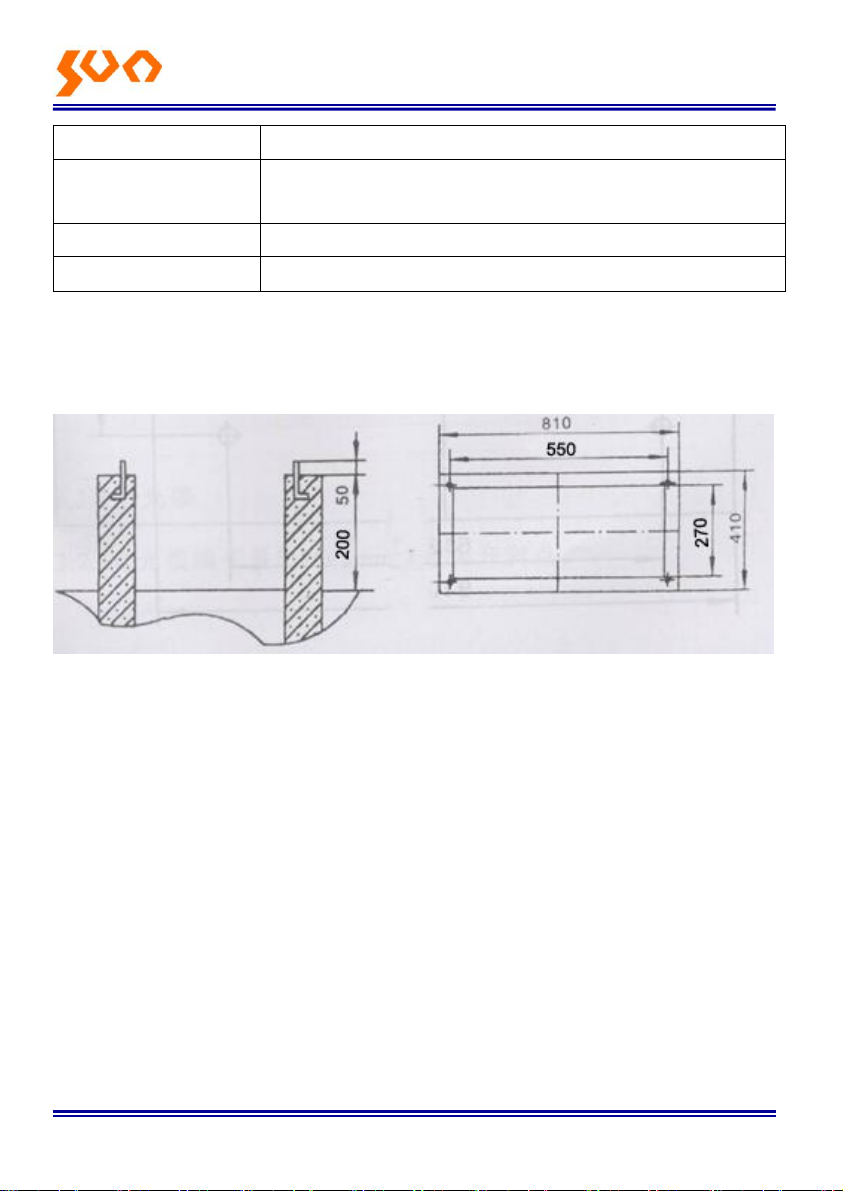
Picture 3
3.2.7 Clean up the optical fiber loose tube, strength member and wrapping
cord. Please wipe outwards from integrated aluminum sheath breaking point,
opposite direction is prohibited, to avoid the loose tube breaking. It is
forbidden to use gasoline and other flammable solvent scrubbing in case of a
fire.
3.2.8 The fiber loose tube is bent caused by wring. Straighten the tube with
electric hair drier and avoid overheating to prevent the loose tube from
softening deformation.
3.2.9. Crosswise carve a circle scratch on the loose tube surface with the
cutting knife and the carving point is 450mm away from the integrated
aluminum sheath breaking end. Gently break the loose tube in the scratched
point and remove it. Please don’t cut the loose tube in case of the damage of
the optical fiber.
3.2.10. Clean up the filling gel of the optical fiber. Please along the loose
tube-fiber end direction when wipe and the opposite direction is forbidden.
3.2.11. If necessary, you can stick the loose tube and fiber can be sticked
3.3 The fix and grounding of the cable inlet device
3.3.1 Put the cable into the device through the bottom of the cabinet and then
into the cable fixing and grounding protection device
3.3.2 Strip the cable from 100mm ahead from where the hose hoops fixed at
with the special cable stripping knife and protect the fiber with sheath. The
length of stripping should be from 100mm to 1000mm.