Sunbeam Luna User manual
supporting sustainability
Steel roof
Portrait
December 2022 | Version 1.0 | This is the English translation of the original Dutch installation manual
Sunbeam Luna
Installation manual
EN

Components
F G
A
B
C
D
E
A Mounting profile
B Mid clamp
C End clamp
D Self-drilling screw
E LunaLiner
F Optimiser adapter
G Mounting kit
General
Description of the user
This document is intended for the installer. Sunbeam Luna should only be installed by a trained installer who has fully read and understood the contents of this
manual.
Intended use and reasonably foreseeable misuse
This type of Sunbeam Luna is suitable for mounting on trapezoidal steel roofs, corrugated steel roofs and pitched even roofs (bitumen, PVC, EPDM, TPO).
Sunbeam Luna must only be used according to the instructions in this document. Sunbeam Luna must only be used with the original accessories and
components supplied by the supplier. Any other use is considered improper use and may lead to injury, damage to the system and void the warranty.
Symbols used
Symbol Meaning
WARNING
This symbol indicates a hazardous situation which, if not avoided, could result in serious injury or death.
NOTICE
This symbol indicates situations not related to personal injury.
COMMENT
This symbol indicates useful additional information.
Safety equipment
Always wear personal safety equipment and fall protection while installing Sunbeam Luna.
Safety instructions
WARNING
NOTICE
• Always follow the national safety regulations in the country of installation.
• Always use fall protection while installing the system.
• Preferably carry out system installation with at least two trained
installers.
• Always ensure that the roof is free of obstacles and clean during
installation of the system.
• Do not install the system in high winds or when the roof is wet.
• Always ensure that the AWP or ladder is on a firm and stable surface.
• Some roofs are not strong enough to support the system. Always check
the condition and strength of the roof before installing the system.
• Always wear personal protective equipment while installing the system.
• Always use the configuration plan derived from the Sunbeam Calculator
software during installation.
• Use only original parts or fittings recommended and sold by Sunbeam.
• Never walk over the system or solar panels.
Preparation
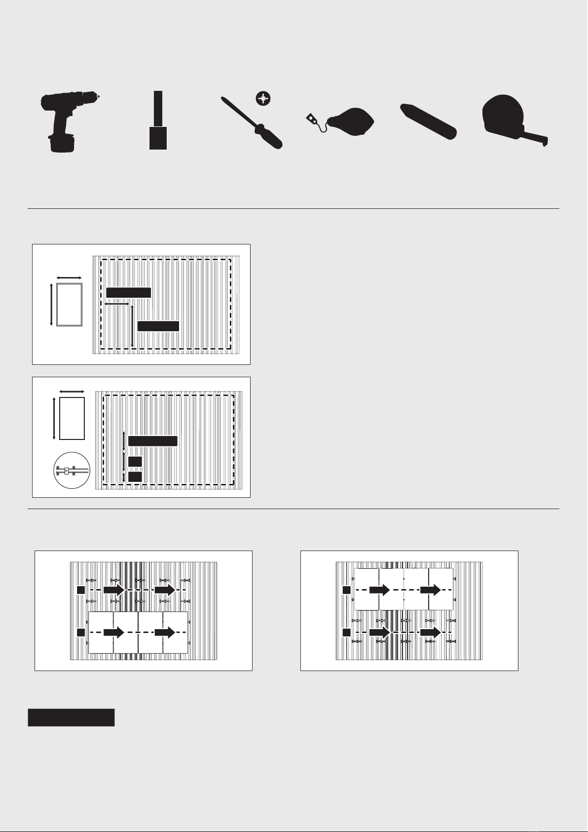
Recommended tools
Electric screwdriver Socket bit 5/16" or 8 mm
Socket bit 3/8" or 10 mm Phillips screwdriver Chalk line reel Chalk Tape measure
Marking the installation area
L + 10 mm
W + 10 mm
W
L
1. Using a tension line or chalk line, mark the outer contours of the field.
2. Mark the panel ends 10 mm away from the panel to account for the clamping width.
L½
L¼
L½ + 10 mm
W
L
3. Mark the positions of the panel clamps. Consult the panel installation manual for the
exact clamping positions.
Laying method
There are two different methods for placing the panels, namely:
2
1
1
2
Bottom-to-top method Top-to-bottom method
COMMENT
In this document, the illustrations show the bottom-to-top method.
Portrait
system installation
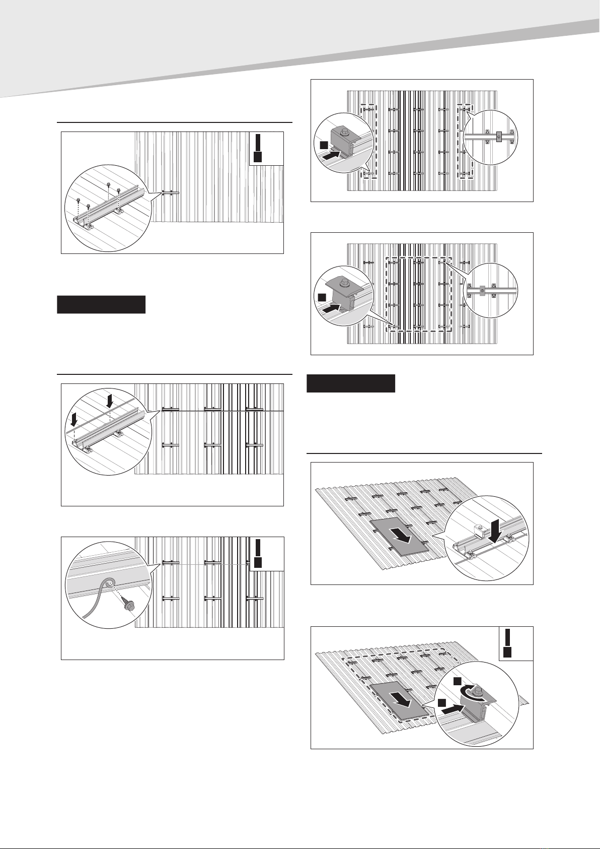
Installing the mounting profiles
3-4 Nm
5/16”
1. Align the mounting profile with the marked profile positions.
2. Tighten the four screws of the mounting profile into the roof.
3. Repeat steps 1 and 2 to install the other mounting profiles.
COMMENT
Turn the last column of mounting profiles
180° relative to the other columns so that no excess profile is
protruding.
Preparing to place the panels
1. Clamp the return cable of the solar power system into the bottom
of the upper cable clamps. This neatly conceals the return cable.
3-4 Nm
5/16”
2. Optional: Install the earthing cables on the side of the mounting
profiles with a self-drilling screw.
1
3. Place an end clamp in the first and last column of the mounting
profiles in line with the marked panel ends.
1
4. Place a mid clamp in the middle rows of the mounting profiles.
COMMENT
Leave space between the first column
end clamps and the first column mid clamps so that the panel can be
easily laid between them.
Placing the panels
1. Position the first panel against the two end clamps at the corner
of the field.
2. Clamp the panel cable into the cable clamp.
5-9 Nm
3/8”
2
1
3. Align the panel with the field contour. Slide the end clamps
against the panel. Tighten the screws of the end clamps.
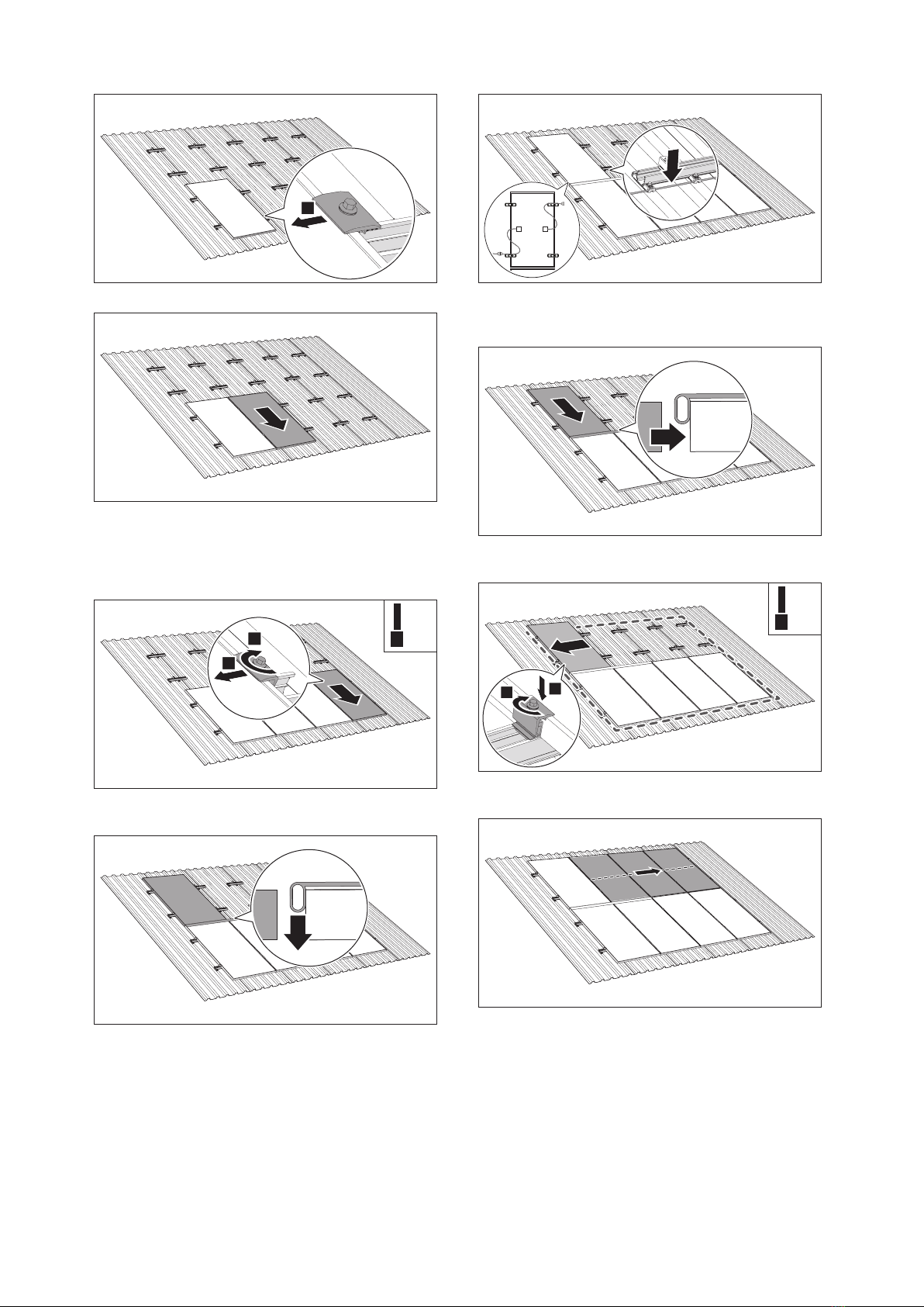
1
4. Slide the 2 mid clamps against the panel.
5. Position the second panel between the mid clamps.
6. Connect the panel cables and clamp them in the top cable clamp.
7. Slide the panel against the first column of mid clamps and tighten
the screws.
8. Repeat steps 5 to 7 to install the first row of solar panels.
5-9 Nm
3/8”
2
1
9. Slide the two end clamps against the last panel and screw them
in place.
10. Place the LunaLiner on the previous row of solar panels.
11. Bring the next panel into position.
12. Connect the panel cables to the return cable of the other row of
panels.
13. Clamp the panel cables into the cable clamps.
14. Lower the panel. Slide the panel against the LunaLiner to
determine the spacing between the panels.
5-9 Nm
3/8”
21
15. Align the panel with the field contour. Tighten the screws of the
end clamps.
16. Repeat steps 10 to 15 to place the rest of the panels.

6
December 2022 | Version 1.0
This is the English translation of the original Dutch installation manualwww.sunbeam.solar/en
Sunbeam BV
Kwikstaartlaan 18
NL-3704 GS Zeist
The Netherlands
+31 (0)30 - 43 00 333
Sunbeam Luna
Installation manual
EN
'Sunbeam' is a registered trademark.
The Sunbeam designs are protected by several international patents.
Safety standards
The national regulations in the country of installation must be observed at all times. Make sure you are aware of the safety measures prescribed by
Sunbeam or the country of installation. If in doubt, consult your safety officer. Ensure safety or health hazards are shared with the employer, supervisor
and executive worker for their information.
General safety
• For the Netherlands: Working Conditions Decree Articles 3.16, 7.23 and 8.1 to 8.3.
• For Belgium: General Regulations for Occupational Health and Safety (ARAB).
Electrical installation
• For the Netherlands:
• NEN1010 - Chapter 7.12
• NPR 5310 - Chapter 7.12
• NEN 3140
• For Belgium: General Regulations on Electrical Installations (AREI).
Roof construction and various loads
• General:
• EN 1990
• EN 1991-1-3
• EN 1991-1-4
• For the Netherlands: NEN 7250
Sustainability
As a manufacturer and supplier of panel mounting systems, we are committed to protecting the environment. In the event of a faulty system, please
contact Sunbeam first. It may still be possible to repair the system.
Should you need to dispose the system, please dispose of the system according to the local applicable regulations. By properly disposing of the various
materials, you will help prevent potential hazards to the environment and human health. The recycling of materials also contributes to the conservation
of natural resources.
Warranty
Please refer to www.sunbeam.solar/en for warranty conditions.
Table of contents
Popular Solar Panel manuals by other brands


NexPower
NexPower NT AF Series installation manual

Sharp
Sharp NU-AH370 installation manual

Goodwe
Goodwe GALAXY Series installation manual

Panasonic
Panasonic EverVolt EVPV Series General installation manual

SUNRI SOLAR
SUNRI SOLAR SR220-250P SERIES Mounting manual

Schweizer
Schweizer Solrif Quick instruction manual


