manuals.online logo
Brands
  1. Home
  2. •
  3. Brands
  4. •
  5. SunBriteTV
  6. •
  7. TV Mount
  8. •
  9. SunBriteTV SB-CM-T-M-BL User manual

SunBriteTV SB-CM-T-M-BL User manual

SB-CM-T-M-BL
SB-CM-DT-M-BL
Weatherproof Universal Single & Dual Ceiling Mount
for Medium TVs
INSTALLATION MANUAL
2
WARNING
• We highly recommend this product be installed by a qualied professional. Do not install if you have doubts regarding the
e󰀨ectiveness or safety of an installation method.
• Please do not begin installation until you have thoroughly read and understood these instructions. Failure to comply with
these instructions could result in damage to the product, or serious injury, or death.
• Do not install if any parts are missing or defective. Do not attempt to replace with unapproved parts or materials or install
without all required parts.
• This mount supports display mounting from VESA 75x75, 100x100, 200x100, and 200x200
• This mount supports a maximum load of 36.4 kg (80 lb).
• Ensure the ceiling will safely support the combined weight of the mount and your chosen display.
• TV display should be removed from mount in situations of high wind exceeding 97 kph (60 mph).
• All assembly fasteners and mounting plate attachment to ceiling should be inspected for signs of loosening or damage
after any strong wind event and at least once annually. If any fasteners have loosened, retighten. If any damage is
observed, remove mount from service.
• The manufacturer does not accept responsibility for incorrect installation.
CAUTION:
These ceiling mounts are intended for use only with the maximum weight of 36.4 kg (80 lb).
SPECIFICATIONS BOX CONTENTS TOOLS REQUIRED
• Maximum load: 36.4 kg (80 lb) • Ceiling plate assembly (1) • Power drill
• Extension: 0.91 m (3 ft.) • Mounting head (1) • 3/16" (5 mm) drill bit
• Stainless steel mounting hardware • Adapter plate (1 or 2) • 5/16" (8 mm) masonry bit
• Pan/swivel range: 360° • 0.91 m (3 ft.) fixed extension pole (1) • 1/2" (13 mm) wrench
• Tilt range: +0°/-20° • Hardware kit (1) • Phillips-head screwdriver
• Weather-resistant coating • 3/8" socket wrench
• VESA patterns: 75×75, 100×100,
200×100, and 200×200
• 7/16" socket wrench
HARDWARE KIT CONTENTS
M4 × 12 mm Phillips-
head screw (×4/8)
M6 × 12 mm Phillips-
head screw (×4/8)
M8 x 16 mm Phillips-
head screw (×4/8)
Hex wrench, 2.5 mm,
security (x2)
Hex wrench, 4 mm (×1)
Security wrench (×1)
M4 × 20 mm Phillips-
head Screw (×4/8)
M5 × 30 mm Phillips-
head screw (×4/8)
M6 × 30 mm Phillips-
head screw (×4/8)
M5 × 12 mm Phillips-
head screw (×4/8)
M6 × 20 mm Phillips-
head screw (×4/8)
M5 (16 × 5.3 × 1.5 mm)
metal washer (×4/8)
M6 (17.8 × 6.5 × 1.5 mm)
metal washer (×4)
M8 (20.5 × 8.5 × 2 mm)
metal washer (×8/16)
#14 × 2.5" lag screw (×4)
M4/M5/M6 spacer:
12 mm (×4/8)
M5 x 5 mm set screw (x4)
M5 x 5 mm set screw,
security (x4)
M8 x 20 mm Phillips-
head screw (×4/8)
3
INSTALLATION
Step 1: Mark Mounting Hole Locations
Place the ceiling plate on the mounting surface and mark the mounting
hole locations.
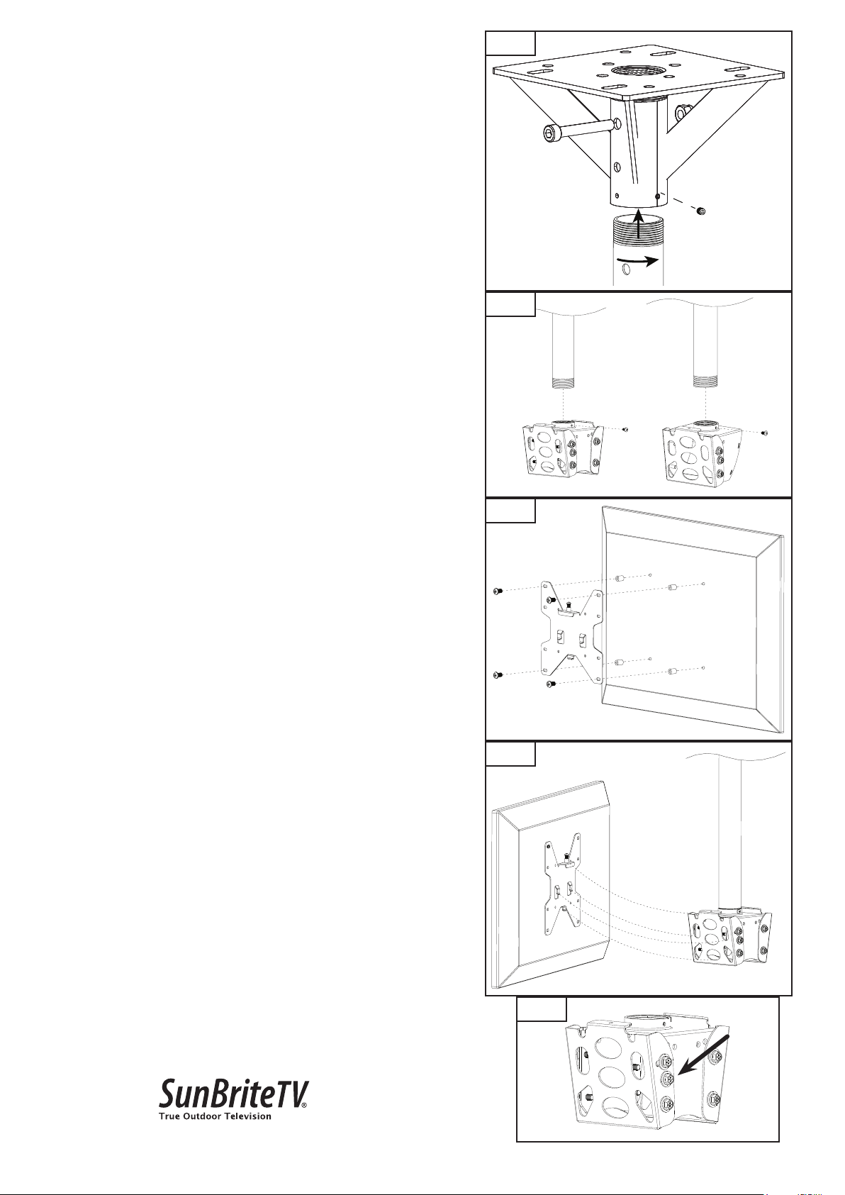
Step 2: Mount the Ceiling Plate
For Mounting on a Wood Joist (Fig. 1)
a. Drill two holes into joist using a 3/16" drill bit. Be sure to drill into the
center of the joists.
b. Insert two lag screws into holes through the ceiling plate and tighten
down.
WARNING: Tighten screws so that the ceiling plate is rmly
attached, but do not over tighten. Over-tightening can damage
the screws, greatly reducing their holding strength.
For Mounting on a Concrete Ceiling (Fig. 2)
NOTE: Concrete anchors not provided. We recommend an outdoor-
rated 5/16"× 2 1/2"wedge or sleeve anchor for concrete or cinder
block installation.
WARNING: When installing ceiling plate on cinder block, verify rst
that you have a minimum of 1-3/8"of concrete thickness to be used
for the concrete wall anchors (not included). Do not drill into mortar
joints! Be sure to mount in a solid part of the block, generally
1" minimum from the side of the block. Cinder block must meet
ASTM C-90 specications. It is suggested that a standard electric
drill on slow setting is used to drill the hole instead of a hammer
drill to avoid breaking out the back of the hole when entering a void
or cavity.
Concrete must be 2000 psi density minimum. Lighter density
concrete may not hold anchor.
a. Drill four holes into concrete using 5/16" masonry bit. Insert hex sleeve
anchors (not supplied) and insert per instructions included with wall
anchors.
b. Remove washer and nut from end of bolt from all four anchor studs.
Place ceiling plate over bolts so they align with the four holes in ceiling
plate.
c. Re-install washer and nut onto end of bolt and tighten down using a
7/16" socket wrench until secure per instructions included with wall
anchors.
WARNING: Tighten screws so that the ceiling plate is rmly
attached, but do not over tighten. Over-tightening can damage
the screws, greatly reducing their holding strength.
For mounting to structural steel beam/plate (Fig. 3)
Note: Mounting hardware for this method not provided. 5/16" (or M8
equivalent) diameter hardware of su󰀩cient length is recommended.
Bolts are recommended to be one of the following:
• Imperial: Grade 5 with a corrosion-resistant coating (zinc plating or
dip-spin coating) or stainless steel (ASTM F593)
• Metric: Grade 8.8 with corrosion-resistant coating (zinc plating or dip-
spin coating) or M8 Property Class 70 or greater for stainless steel
(A2-70)
• A at washer should be used against the mounting plate slots, and a
nylon-insert lock nut is recommended
WARNING: Steel structure must be specied to support
additional load of mount and TV.
a. Drill four holes using a 3/8" bit through the steel plate.
Fig. 1
Fig. 2
Fig. 3
4
Step 3: Attach the Extension Pole
Thread in extension pipe so that the holes in the pipe align with the
holes in the bracket, then tighten the through-bolt and tighten the set
screw (Fig. 4).
Step 4: Attach the Mount Head
Screw the mount head on to the end of the extension pole and tighten
set screw (Fig. 5).
Step 5: Attach the Adapter Plate to the Display
Attach the adapter plate to the display using M4, M5, M6, or M8
screws. For displays with a hole pattern in a pocket or inputs behind
adapter plate, spacers go between adapter plate and display (Fig. 6).
Step 6: Attach the Adapter Plate with Display to Ceiling Mount
Assembly
a. Attach adapter plate and display onto wall arm assembly, ensuring
all three hooks slide into holes of mount head (Fig. 7).
b. Using a Philips screwdriver, tighten down the locking screw located
on adapter plate into threaded hole in the mount head.
ADJUSTMENTS
Tilt Adjustment
a. Loosen screws on side of mount head (only enough to allow
controlled adjustment) (Fig 8).
b. Adjust tilt forward or backward.
c. Retighten screws, then check to ensure that tilt angle is locked in
place.
Fig. 5
Fig. 6
200-SB-CM-T-M-BL-001 Rev B 20210524MS
Copyright ©2021, Wirepath Home Systems, LLC. All rights reserved.
Control4 and SnapAV and their respective logos are registered
trademarks or trademarks of Wirepath Home Systems, LLC, dba
“Control4” and/or dba “SnapAV” in the United States and/or other
countries. Snap AV, SunBriteDS, SunBriteTV, Wirepath, and
Wirepath ONE are also registered trademarks or trademarks of
Wirepath Home Systems, LLC. Other names and brands may be
claimed as the property of their respective owners. SnapAV makes
no claim that the information contained herein covers all installation
scenarios and contingencies, or product use risks. Information within
this specication subject to change without notice.
WARRANTY AND LEGAL INFORMATION
Find details of the product’s Limited Warranty at snapav.
com/warranty or request a paper copy from Customer
Service at 866.424.4489. Find other legal resources,
such as regulatory notices and patent information, at
snapav.com/legal.
Technical Support: 866.838.5052
Fig 7
Fig. 8
Fig. 4

This manual suits for next models

1

Other SunBriteTV TV Mount manuals

SunBriteTV SB-CM-T-L-BL User manual

SunBriteTV

SunBriteTV SB-CM-T-L-BL User manual

SunBriteTV SB-POLE-A-S-BL User manual

SunBriteTV

SunBriteTV SB-POLE-A-S-BL User manual

SunBriteTV SB-DP46XA User manual

SunBriteTV

SunBriteTV SB-DP46XA User manual

Popular TV Mount manuals by other brands

Init NT-TVM105 Assembly instructions

Init

Init NT-TVM105 Assembly instructions

Philips SQM5222/27 Specifications

Philips

Philips SQM5222/27 Specifications

Multibrackets M Universal Fixed Wallmount HD installation manual

Multibrackets

Multibrackets M Universal Fixed Wallmount HD installation manual

Insignia NS-HTVLGTILT-C installation guide

Insignia

Insignia NS-HTVLGTILT-C installation guide

Gladiator Joe GJ0A0020 quick start guide

Gladiator Joe

Gladiator Joe GJ0A0020 quick start guide

peerless-AV SA771P Installation and assembly

peerless-AV

peerless-AV SA771P Installation and assembly

Panasonic WV-Q193 operating instructions

Panasonic

Panasonic WV-Q193 operating instructions

Bell'O 7640 instruction manual

Bell'O

Bell'O 7640 instruction manual

Sanus Systems FFMF2A product manual

Sanus Systems

Sanus Systems FFMF2A product manual

Forging Mount HY9190 installation instructions

Forging Mount

Forging Mount HY9190 installation instructions

Atlantic Technology ICTS-6.3 installation instructions

Atlantic Technology

Atlantic Technology ICTS-6.3 installation instructions

JKS OGS162 Installation instructions manual

JKS

JKS OGS162 Installation instructions manual

PEERLESS PLA 60  and assembly Installation and assembly manual

PEERLESS

PEERLESS PLA 60 and assembly Installation and assembly manual

Kimex 030-3002 instructions

Kimex

Kimex 030-3002 instructions

USX-MOUNT SML016-24K-01 instruction manual

USX-MOUNT

USX-MOUNT SML016-24K-01 instruction manual

Velocity VDOT-ADP instruction manual

Velocity

Velocity VDOT-ADP instruction manual

ONKRON G120 user guide

ONKRON

ONKRON G120 user guide

Nautilus Be Strong. NV915 Assembly manual

Nautilus

Nautilus Be Strong. NV915 Assembly manual

manuals.online logo
manuals.online logoBrands
  • About & Mission
  • Contact us
  • Privacy Policy
  • Terms and Conditions

Copyright 2025 Manuals.Online. All Rights Reserved.