Sundown Audio P-PRO 180 User manual

CENTRIFUGAL SALT SPREADER
Mod. P-PRO
OPERATOR’S MANUAL
Read the Operator’s manual entirely before using the machine

2
INDEX
1 INTRODUCTION .............................................................................................................................................................................. 3
2 GENERAL INFORMATION .............................................................................................................................................................. 3
2.1 USING THIS MANUAL .......................................................................................................................................................... 3
2.2 INFORMATION ON THE MACHINE ...................................................................................................................................... 4
2.3 NAME PLATE ........................................................................................................................................................................ 4
2.4 CHARACTERISTICS OF THE MACHINE .............................................................................................................................. 4
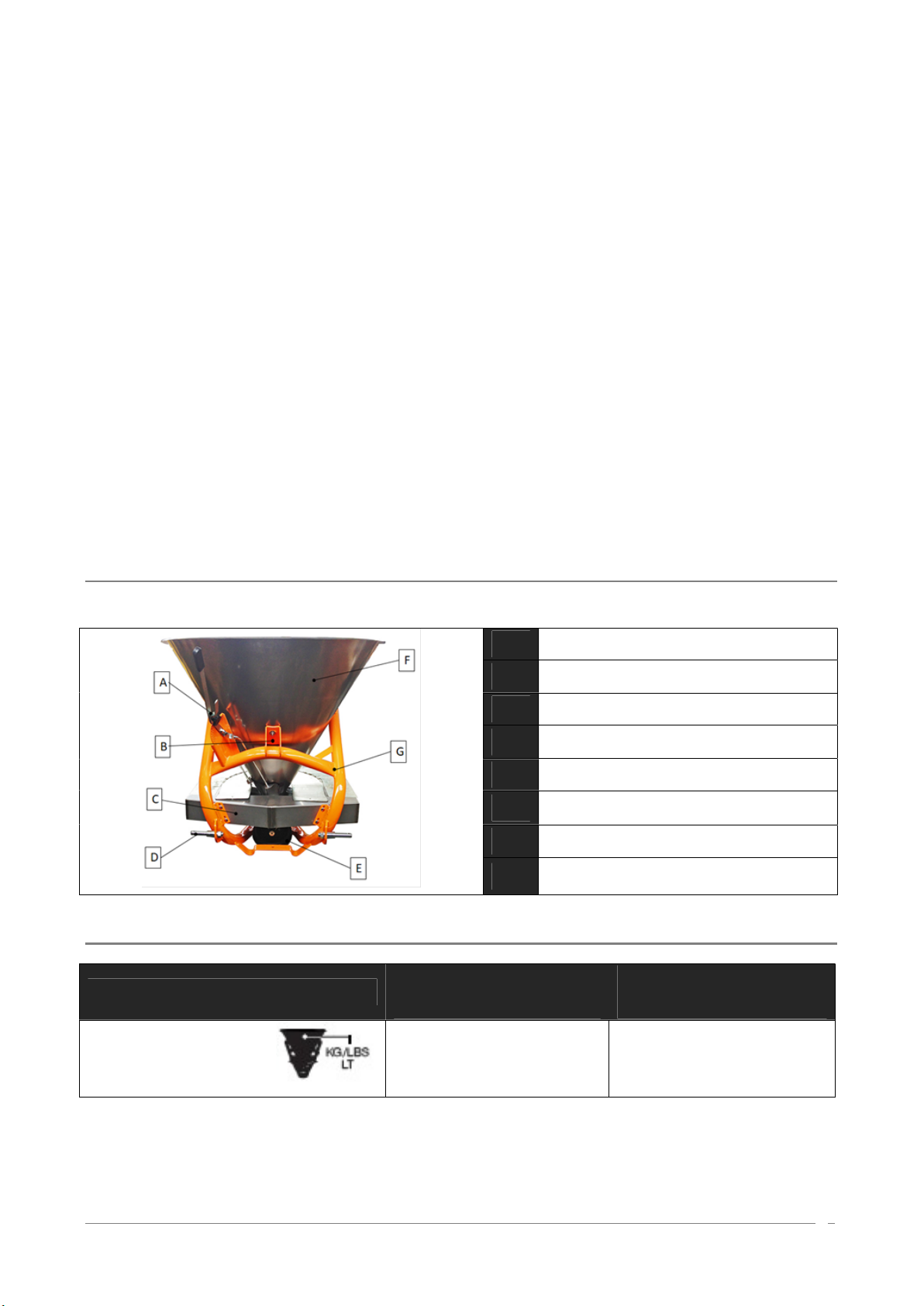
2.5 IDENTIFICATION OF COMPONENTS .................................................................................................................................. 5
2.6 TECHNICAL DETAIL ............................................................................................................................................................. 5
3 SAFETY INFORMATION .................................................................................................................................................................. 6
3.1 GENERAL ADVICES ............................................................................................................................................................. 6
3.2 CONNECTION OF THE MACHINE TO THE TRACTOR ........................................................................................................ 8
3.3 OPERATION ON THE MACHINE .......................................................................................................................................... 9
3.4 TRANSFER ON THE ROAD ................................................................................................................................................ 10
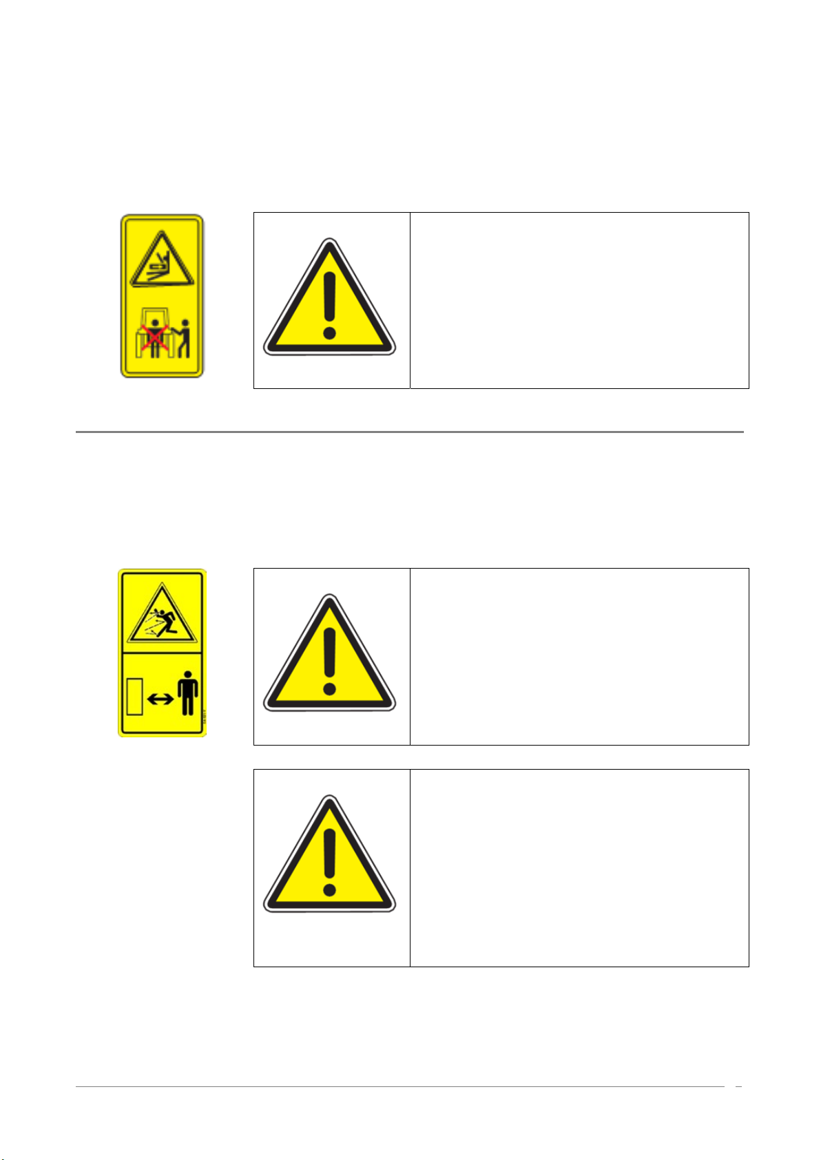
4 SAFETY SIGNALS ......................................................................................................................................................................... 10
5 ASSEMBLY AND SET-UP ............................................................................................................................................................. 12
5.1 TRACTOR REQUIREMENTS AND 3-POINT HOOK-UP ..................................................................................................... 12
5.2 CONNECTION TO THE 3-POINT HITCH OF THE TRACTOR ............................................................................................ 13
5.3 DRIVELINE INSTALLATION................................................................................................................................................ 14
6 SALT SPREADER USE ................................................................................................................................................................. 15
6.1 RECCOMENDATIONS FOR A CORRECT DISTRIBUTION ................................................................................................ 15
6.2 ADJUSTMENTS .................................................................................................................................................................. 15
6.3 HOW TO ADJUST THE SPREADING VANES .................................................................................................................... 16
6.4 SPREAD PATTERN ............................................................................................................................................................ 16
6.5 HOPPER LOAD ................................................................................................................................................................... 18
6.6 SPREADING WIDHT ADJUSTMENT .................................................................................................................................. 18
6.7 SPREADING CHART AND PROFESSIONAL LIMITER SPREADING ADJUSTMENT ......................................................... 20
7 SPREADING MISTAKES ............................................................................................................................................................... 21
7.1 MISTAKES OF USE ............................................................................................................................................................ 21
7.2 MISTAKES DUE TO SALT .................................................................................................................................................. 21
7.3 MISTAKES DUE TO THE SPREADER ................................................................................................................................ 21
8 MAINTENANCE ............................................................................................................................................................................. 21
8.1 LUBRIFICATION ................................................................................................................................................................. 23
8.2 REPLACMENT OF DISTRIBUTOR VANES......................................................................................................................... 23
8.3 LONG-TERM STORAGE ..................................................................................................................................................... 24
8.4 SPARE PARTS ................................................................................................................................................................... 24
9 WARRANTY ................................................................................................................................................................................... 24
10 PARTS BREAKDOWN ................................................................................................................................................................... 26
10.1 GENERAL VIEW ................................................................................................................................................................. 26
10.2 GEAR BOX – 322.029 ......................................................................................................................................................... 28
10.3 SPREADER DISC WITH DISTRIBUTOR VANES – 610.119 ............................................................................................... 29
10.4 SALT AGITATOR – 620.108 ................................................................................................................................................ 30
10.5 STANDARD LIMITER – 620.122 ........................................................................................................................................ 31
10.6 RIGHT LEVER – 618.026 ................................................................................................................................................... 32
10.7 LEFT LEVER – 618.027 ..................................................................................................................................................... 33
11 OPTIONAL PARTS BREAKDOWN ................................................................................................................................................ 34
11.1 GENERAL VIEW ................................................................................................................................................................. 34
11.2 WHEELS KIT – 613.301 ...................................................................................................................................................... 35
11.3 LIGHTS AND SUPPORTS KIT – 620.187 ............................................................................................................................ 36
11.4 STAINLESS PROGRESSIVE LIMITER KIT – 620.163 ........................................................................................................ 37
11.5 HYDRAULIC OPENING SYSTEM – 619.111 ....................................................................................................................... 38
11.6 SHOVEL SUPPORT KIT – 613.350 ..................................................................................................................................... 39

3
1 INTRODUCTION
The SALT spreaders are machines used for the distribution of solid, in the field. They can
be used whether with tractors of small/medium power.
It is recommended to carefully read this operator’s manual of use and maintenance and follow the
recommendations to help ensure safe and efficient operation with and on the machine.
This manual has been written, in order to give the customer all the information and safety rules on the
machine, as well as use and maintenance instructions that let to make good use of the potentialities of the
machine.
The manual must always be handy, so as to consult it, in order to check the operational cycle. If it gets lost
or damaged, it will be necessary to ask for a substitutive copy.
In case of some difficulties of interpretation on texts or tables, or if the drawings/sketches are not clear
enough, please get immediately in touch with the manufacturer or dealer of the machine for having all the
clarifications through the experts in the working/maintenance or through the person who wrote the manual.
We are completely available for a real collaboration, in order to improve the understanding of the whole
manual.
2 GENERAL INFORMATION
2.1 USING THIS MANUAL
This manual gives all the information for the use and maintenance of the machine. The good working and its
life depends on the good maintenance and to the attention during the use.
Some pictures in this manual show details or accessories that could be different from those of your
machine, some components could be removed, in order to assure the clearness of the pictures.
Some signal words are put on the machine and the operator shall see to keep them in a perfect visual
condition, replacing them when they are not readable anymore.
The symbol on the left, joined to the words under shown:
DANGER!
ATTENTION!
WARNING!
is used in this manual to draw your attention on the safety and good
work of the machine. Therefore, it is necessary to observe all the
written rules.

4
2.2 INFORMATION ON THE MACHINE
The models introduced in this manual have been designed and made exclusively allowing the
distribution of salt. The machine is not indicated for being used in different sectors from the agricultural one.
These machines are usually used during the day. If it is required the nocturnal use or with poor
visibility, it must use the lighting system of the tractor or of the equipment to which the machine is
connected.
A different use, like the above mentioned one is considered improper.
Any arbitrary modification made to this machine relieve the manufacturer from any responsibility for damages
or lesions, also serious, that can be caused to the operators, to third parties or to things.
We recommended to use the original spare parts and accessories. The not original parts, besides to decline
the guarantee, could be dangerous reducing the length and the performances of the machine.
2.3 NAME PLATE
On the frame of every machine, a name plate is fixed showing the model, the number of series and the year
of construction of the machine.
When some spare parts are required, it is always necessary to refer to the type of machine, to the serial
number and to the manufacturing year.
2.4 CHARACTERISTICS OF THE MACHINE
The SALT spreaders series COSMO can rely on a huge range of models adaptable with tractors of any
owner.

5
The strength of the welded steel frame, combined with the considerable durability of the stainless steel
hopper, allows to obtain a very high overall quality level in the category to which the distributors of carried
SALT spreader.
The SALT spreader P-PRO model has a distributor completely in stainless steel equipped with a spreader
disc with four adjustable vanes in four different positions, in order to obtain the maximum spreading
precision and uniformity in the distribution.
The feeding of the disc is by gravity through two opening, located on the side of the hopper, inside
of which a mix/agitator is applied, in order to prevent the SALT lumps formation. The side discharge ensures
greater uniformity of spreading as the SALT falling on disk is immediately hit by the vanes without
dispersions and making sure that each pallet receive the same amount of SALT.
A sheet case is placed in front of the disc, in order to prevent the spreading in the front side of the machine.
The dosage of the product takes place by varying the section of the hopper openings by means of a split
lever system so as to allow even spreading to the right or left with respect to the direction of progress.
The SALT spreader is connected through a gear box (1:1) with gears module 17 in order to be resistant,
absorbing possible power stress.
2.5 IDENTIFICATION OF COMPONENTS
A Adjusting lever
B Third hitch point
C Rear shield
D Hitch pin
E PTO shaft hitch
F Hopper
G Steel frame
H Vanes
2.6 TECHNICAL DETAIL
Mod. P-PRO
180
P-PRO
300
CAPACITY
200/441/170 320/705/270

6
WEIGHT
54/119 58/128
DIMENSIONS
(W/OUT PTO SHAFT)
950x950x950 1050x1050x1050
SPREADING WIDTH
1-14 m / 3.46 ft
MINIMUM HP
20 CV/HP
3 SAFETY INFORMATION
THE FOLLOWING SAFETY RECCOMENDATIONS ARE TO SAFEGUARD YOUR INCOLUMITY THEREFORE IT IS
NECESSARY TO READ THEM CAREFULLY, MEMORIZING AND ALWAYS APPLYING THEM.
The present warnings in this manual regard exclusively the allowed uses and reasonably
foreseeable.
All below instructions must be integrated by the common sense and by the experience of who works,
indispensable measures to prevent accidents.
The machine must be used by a single operator. It is forbidden the use of the machine to under-ages. All the
listed instructions must be carefully respected.
Possible changes on the machine, not preventively authorized by the manufacturer (by written copy),
exclude his responsibility.
Check the correct functioning of the machine, before every employment.
3.1 GENERAL ADVICES
• Read carefully this manual before proceeding to start, operate, employ or maintenance on the
machine.
• Watch, in addition to the warnings of this manual, all the safety, accident prevention rules and of general
nature.

7
• The manual must always be handy , so as to consult it, in order to check working cycle and safety
information. In case of loss or damage, it will be necessary to ask for a substitutive copy.
ATTENTION!
Any work of maintenance, regulation and
cleaning must be done with the machine on
the ground (in stable conditions), turning off the
tractor engine and
removing the key.
• Read carefully the safety signal words applied on the machine and follow the instructions. In case of wear
and tear or insufficient readability of the safety signal words, clean them up or replace them, placing the
signal words in the right position, as shown in paragraph 4.
ATTENTION! WARNING!
The operator, during the period of use, maintenance, repair,
handling or storing of the machine, must wear accident-
prevention shoes and safety gloves. Moreover, if it is
necessary he must wear suitable hearing protections such
as earmuffs or earplugs, dust masks and protective glasses
• Keep the machine cleaned up from foreign bodies (detritus, tools, miscellaneous), as they could
damage the operations or the operator. Generally the SALT are rather corrosive. For this reason, it is
important that any particle of the SALT stay in the machine for a long period of time. Clean
the hopper and the distributor after each use of the machine.
DANGER!
It is forbidden to climb or to transport somebody
when the machine is in motion. Do not let inside
the hopper for any reason

8
• If during cleaning operations it is used air or water with pressure, it is necessary to wear glasses and
safety masks keeping away possible persons or animals from the machine.
• Before connecting the machine to the tractor or to other self-moving means check that this is in
good conditions and that brakes work correctly, especially if you work on sloping grounds.
• Switch off the machine from tractor only on a compact and level ground (with empty hopper),
checking that the machine is stable.
WARNING!
During transport operations, stocking and employment of the SALT, the
operators must follow all the label indications and particularly to the content
of the written risks and the precaution suggestions
THE MANUFACTURER DOES NOT ANSWER TO POSSIBLE DAMAGES CAUSED BY AN IMPROPER AND
UNFORESEEN USE OF THE MACHINE
THE MANUFACTURER IS NOT RESPONSIBLE IN CASE
OF:
IMPROPER USE OF THE MACHINE, USE BY NOT TRAINED STAFF, SERIOUS DEFICIENCIES IN THE FORESEEN
MAINTENANCE, CHANGES OR NOT ALLOWED INTERVENTIONS, USE OF NOT ORIGINAL OR SPECIFIC SPARE
PARTS, TOTAL OR PARTIAL INOBSERVANCE OF THE INSTRUCTIONS, INOBSERVANCE OF THE COMMON
SAFETY RULES DURING WORK, UNUSUAL CASES.
3.2 CONNECTION OF THE MACHINE TO THE TRACTOR
• The third hitch point of the tractor and the SALT spreader must coincide or must be adapted.
• Make sure that the PTO shaft is engaged in right way after every linkage operation of the machine and that
it does not come uncoupled when the machine is lowered in order to fill the hopped up.
ATTENTION! DANGER!
Check that the protections of the PTO shaft are
complete and in good conditions.
• In case of breaking or deterioration of the PTO shaft protections, please replace them immediately.

9
• When the machine is not linked to the power unit, the PTO shaft must be placed on the appropriate
support.
• The presence of the machine can influence the manoeuvrability of the tractor, in particular during transport.
ATTENTION!
Do not come, for any reason, between the tractor
and the SALT spreader when the engine is
running and the power take-off is on.
3.3 OPERATION ON THE MACHINE
• Make a check of the machine before switching it on. Start to work only if the machine is in perfect
conditions.
• Before using the machine, please be sure that all the safety devices are correctly placed and in good state;
in case of breakdowns or damages to the protections, please replace them immediately.
ATTENTION!
During work, please be sure that for a radius of
50 meters there are not any person or animals.
When you work in proximity of roads or public
places, it is ABSOLUTELY OBLIGATORY to keep
away persons and to increase the precautions.
ATTENTION!
Anybody who comes up to the machine in a
danger area, therefore he becomes “AN
EXPOSED PERSON”. The operator must prevent
anybody to come into the danger area and to
work with the maximum caution. If somebody
comes up, please stop immediately the tractor
engine.

10
3.4 TRANSFER ON THE ROAD
ATTENTION!
Please follow scrupulously the Highway code in force in the Country of use.
During transport on public roads, it is obligatory to empty the hopper.
• Remember that during moving on public roads, special attention must be done, besides to possible and
special regulations noted on the registration book of the tractor, choosing an appropriate speed especially
when the street is crowded, winding or sloping.
• If the spreader hides with its shape the back signalling lights of the tractor, it is necessary to put a lights bar
and/or some back signalling signs.
• During the moving on the road, please clean tyres or the working mechanism, in order to avoid dirty the
feather edge with earth or other material.
ATTENTION!
During the moving on the road, the warning flasher, yellow or orange,
assembled on the tractor must always be in function also during the day.
ATTENTION!
During transport with raised machine, please always check that the control
lever of the rear lifter is locked, in order to avoid the accidental lowering of
the machine.
4 SAFETY SIGNALS
ATTENTION!
Be sure that the safety labels are readable. Clean them up using a cloth,
water and soap. Replace the damaged labels placing them in the right
position, as subsequently described.

11
The safety signals on the machine supply the most important indications: their observance helps your
safeness.
ATTENTION!
Before making any operation on the
machine, stop the engine of the
tractor or of the self- moving means,
remove the key, put on the parking
brake and read carefully the
operator’s manual.
ATTENTION! DANGER! of
entangling and dragging. Do not put
hands near the running gear box.
ATTENTION!
Check the sense of rotation and the
number of revolutions (540 rpm) of
the tractor power before placing the
PTO shaft.
ATTENTION! DANGER! of crushing.
Do not stop between the machine
and tractor when the tractor engine is
running.
ATTENTION! DANGER!
Possible throwing of material and/or
objects, please do not stop or come
up to the machine. Keep a safety
distance of 50 meters, at least, from
the machine.
ATTENTION! DANGER! of shearing.
Do not approach limbs to the
spreader disc when the machine is
running.
ATTENTION!
Use the individual Protection Devices, as required.

12
5 ASSEMBLY AND SET-UP
Before coupling the machine to the 3-point hitch, positioning the safety devices to the tractor, so that it is not
possible the involuntary and/or accidental raising and lowering of the arms.
The 3-point hitch of the tractor and of the machine must coincide or must be adapted.
In proximity of arms rods of the back lifter of the tractor, there is the danger of wounding, because of
crushing and cutting points.
Do not use the external controls for the lifting of the machine. During transport position block the lateral stop
of the rods.
5.1 TRACTOR REQUIREMENTS AND 3-POINT HOOK-UP
DANGER!
It is obligatory to check the raising ability and the stability of the tractor
(before carrying out the connection with the machine) in order to avoid
the overturning and/or the loss of wheels grip.
Before connecting the machine to the tractor is required to check the stability of the tractor machine system,
in order to determine the ballast to apply to the front of the tractor, to ensure adequate distribution of the
weight on the axles.
In order to assure the stability it is necessary that the following relations are verified (see table below for
definitions):
1) M x s ≤ 0.2 x T x i + Z x (d+i)
2) M ≤ 0.3T
Consequently, the minimum ballast required is:
Z min = (M x s - 0.2 x T x i)/ (d+i)
To determine the appropriate characteristics of the ballast, refer to the manual of the tractor.

13
i =
Tractor wheelbase (cm)
d = Distance between front axle and ballast center of mass (cm)
T = Weight of tractor + operator (75 kg)
Z = Ballast weight (kg)
M = Spreader weight + roller weight (if included) (kg)
s = Distance between rear axle and implement center of mass
5.2 CONNECTION TO THE 3-POINT HITCH OF THE TRACTOR
ATTENTION!
Every time that somebody comes down from the tractor, it is necessary to
disconnect the PTO shaft, stopping the engine and to put on the parking
brake.
For the connection of the machine to the tractor, please operate in the following way:
• Step backwards with the tractor until arriving in proximity of the lower connections of the SALT spreader.
• Fix the lower connections of the tractor to the pins of the machine and lock them with the safety plugs.
• Connect the upper linkage of the machine to the 3-point hitch of the tractor putting the appropriate pin and
block the anti-unscrewing device of the 3-point hitch;
• Raise the machine of some centimetres by the ground and operate on the lateral ties of the lifter bars and
on the two turnbuckles, in order to block the lateral movement, so as to prevent excessive oscillations during
the working phase.
The machine must be positioned, through the raising of the lower connections of the tractor, so that the land
distance from the lower extremity of the distributor disc is approximately of 70 cm. To obtain
a regular distribution, it is important that the distributor disc is in horizontal position compared to the land.
• After having made these operations, the PTO shaft must be linked to the splined shaft of the
gearbox of the machine (covered by a safety cowling) and after to the tractor power take-off.
ATTENTION!
The PTO shaft must always be connected to at last to the power take off and
disconnected at first, when you stop working.

14
5.3 DRIVELINE INSTALLATION
Before using the PTO shaft, please consult the use and maintenance manual attached to the pto
shaft.
In case that the PTO shaft, supplied with the machine, is not used, please check that the cowlings of the
machines and of tractors are overlapped to the PTO shaft’s shield of 5 cm., at least.
For a correct and safe operation of the machine, please use exclusively PTO shafts with CE mark.
Please use PTO shafts with integral shields.
• Grease periodically, the PTO shaft following the instruction supplied by the PTO shaft manufacturer
(see the use and maintenance manual of the PTO shaft).
• Observe the sense of assembly of the PTO shaft, as indicated by the manufacturer and shown on the
outer cover of the shield (tractor drawing on the external tube of the PTO shaft towards the power take-off of
the same tractor).
• Fasten the safety ant-rotation chains and make sure that the safety anti- removing block (push
connecting ring nut) is correctly placed and blocked in the right lodging.
ATTENTION!
Check the rotation sense and the speed
regulation of the power take-off of the tractor to
be at 540 rpm, as the machine is projected for
this kind of speed.
The length of the PTO shaft must be adapted to the type of used tractor.
When the PTO shaft is released from the power take-off of the tractor must ALWAYS be laid on the
appropriate support.
THE MANUFACTURER IS NOT RESPONSIBLE FOR THE DAMAGES CAUSED BY AN INCORRECT ASSEMBLY
AND USE OF THE PTO SHAFT.

15
6 SALT SPREADER USE
ATTENTION!
Before use, please check that gears are adequately greased.
ATTENTION!
During the use of the machine, please be sure
that for a radius of 50 meters there are not any
person or animals. If somebody comes up,
please stop immediately the tractor engine.
6.1 RECCOMENDATIONS FOR A CORRECT DISTRIBUTION
• Please test always the kg/ha that you wish to spread before starting to work.
• Use a SALT in perfect conditions: a humid SALT could not be spread uniformly and correctly.
• Avoid to spread the SALT during windy days, in order to improve the uniformity of the distribution.
• Do not connect the power take-off that operates the spreading disc when the tractor is picked up; low RPM
until it idles and afterwards speed up gradually till you can achieve a speed of 540 RPM.
• Open the SALT shutters only when the desired speed is achieved.
6.2 ADJUSTMENTS
It is not possible to have an exact spreading chart for equipment that make use of the centrifugal principle,
given that the distributed quantity depends on the feed speed, on the radius of distribution, on the quality and
humidity of the SALT and on the roughness of the land. The SALT must always be stored and conserved
adequately, so as to keep its physical characteristics unchanged.
It is necessary to set the speed of the centrifugal spreader, before starting the operation of distribution,
trying, in the possible limits, to keep it constant for all its duration.
The spreading charts contain the indicative information, in order to determine the quantity to spread in the
field; these must be completed by the experience and competence of the operator.

16
6.3 HOW TO ADJUST THE SPREADING VANES
In order to assure an homogenous distribution on both sides of the centrifugal spreader, depending on the
different specific weight of the used SALT, the distributor vanes on the disc can have different
positions.
When all the vanes are placed in position 1 (as shown in the picture), the distribution of the product
is increased towards left, compared to the way of the tractor moving. On the contrary, if the vanes are put in
hole 4, the distribution will be bigger towards right.
Moreover, moving the vanes from position 1 to position 4, at the same speed, there will be an increase of the
distributing width of SALT distribution.
DISTRIBUTOR VANE ADJUSTMENT
6.4 SPREAD PATTERN
The SALT spreading is regulated through the regulation lever that moves the opening section on the bottom
of the hopper.
In order to carry out the regulation, after having consulted the spreading table, according to the type of
product to spread and to the spreader speed, it is necessary to move the lever “A” along the graduated scale
“E” and blocking it in the chosen position with the pin “D”. See the further table.

17
Before using the spreader make sure that the shutters could close the holes completely with lever in “closed”
position. Otherwise adjust it through the nuts.
In order to spread from both sides (ref. I), “A” and “B” levers must be in the same position, connected through
grip handle “C”.
In order to carry out the spreading only through the left side (ref. II), it is necessary to disconnect the two
levers removing the “C” grip handle, to set the lever “A” in the chosen position, given by the spreading chart,
and to bring the lever “B” towards the higher part (position 1) in order to close the shutter of the right side.
In order to spread only on to the right side (ref. III) you have to move the lever “A” up, (in position 1) and
regulate the quantity to spread with the lever “B”.
LEFT SIDE DISTRIBUTION (RIF. II) RIGHT SIDE DISTRIBUTION (RIF. III)

18
6.5 HOPPER LOAD
It is advised not to carry out the hopper loading manually but using a lifter or suitable mechanical means.
ATTENTION!
The hopper must be loaded only after having hitched the spreader to the
tractor.
Do not drive for very long distances with a full load and do not put full bags on the fertiliser loaded in the
hopper during the transport to the field or during the working, in order not to overload the capacity
of the machine and to compress the SALT.
WARNING!
During the operations of transport, stock and use of SALTs, the operator
must be behaved in compliance with the indications on the label of the
product and in particular with the content of the sentences of risk and the
precaution advices.
6.6 SPREADING WITH ADJUSTMENT

19
REGOLAZIONE POSIZIONE
Position/Position/Posición/Position
LARGHEZZA SPAGLIO
Spreading width/ Largeur d’épandage/ Ancho de
trabajo/ Streubreite
mm.40 240 mm
mm.50 480 mm
mm.100 Tutto aperto/Full open/Tout ouvert/
Todo abierto/ voll geöffnet
APERTURA
Opening lever position/
Ouverture sur levier/
Apertura en la palanca/
Öffnungshebel Position
Q.tà Kg/m
Q.ty Kg/m
Q.té Kg/m
Cant. Kg/m
Menge Kg/m
6 km/h
Q.tà Kg/m
Q.ty Kg/m
Q.té Kg/m
Cant. Kg/m
Menge Kg/m
8 km/h
Q.tà Kg/m
Q.ty Kg/m
Q.té Kg/m
Cant. Kg/m
Menge Kg/m
12 km/h
4 0,148 (148 for Km) 0,111 (111 for Km) 0,74 (74 for Km)
6 0,576 (576 for Km) 0,432 (432 for Km) 0,288 (288 for Km)
8 0,984 (984 for Km) 0,738 (738 for Km) 0,492 (492 for Km)

20
6.7 SPREADING CHART AND PROFESSIONAL LIMITER SPREADING ADJUSTMENT
REGOLAZIONE POSIZIONE
Position/Position/Posición/Position
LARGHEZZA SPAGLIO
Spreading width/ Largeur d’épandage/ Ancho de
trabajo/ Streubreite
POS.1 2,5 m
POS.2 3,5 m
POS.3 5,0 m
POS.4 8,0 m
POS.5 Tutto aperto/Full open/Tout ouvert/
Todo abierto/ voll geöffnet
APERTURA
Opening lever position/
Ouverture sur levier/
Apertura en la palanca/
Öffnungshebel Position
Q.tà Kg/m
Q.ty Kg/m
Q.té Kg/m
Cant. Kg/m
Menge Kg/m
6 km/h
Q.tà Kg/m
Q.ty Kg/m
Q.té Kg/m
Cant. Kg/m
Menge Kg/m
8 km/h
Q.tà Kg/m
Q.ty Kg/m
Q.té Kg/m
Cant. Kg/m
Menge Kg/m
12 km/h
4 0,148 (148 for Km) 0,111 (111 for Km) 0,74 (74 for Km)
This manual suits for next models
1
Table of contents