Lesco Commercial Plus 024200 User manual

100 LB Rotary Spreader
Optional Equipment
Calibration
024200/Stainless Steel
PARTS LIST AND INSTRUCTIONS
5:1 Gearbox

1
Assembly Instructions
1.Removethespreadercomponentsfromthecarton.You
should find all of the parts shown above plus the Hard-
ware Package. The Hardware Package contains:
2 Cotter Pin, 3/16 x 1-3/4
3 Spacer Washers, 3/4 I.D.
4 Cap Screws, 1/4-20 x 2-1/4, Hex Head
4 Machine Screws, 1/4-20 x 5/8, Phillips Head
5 Machine Screws, 1/4-20 x 1-1/2, Phillips Head
18 Flat Washers, 1/4
13 Hex Nuts, 1/4-20, Nylock
2 Clevis Pin, 1/4 x 1/2
2 Cotter Pin, 3/32 x 1/2
2 Cable Ties
1 C-Clip
2. Place a spacer washer on each side of the axle next to
theaxlebushing.Mountthedrivewheelonthesideofthe
axle with the predrilled hole near the axle bushing as
shown in the illustration. Attach by fastening on the
inside of the wheel with the 3/16 x
1-3/4 cotter pin.
3. Mount the idler wheel on the other side of the axle. Add
a spacer washer and put the 3/16 x 1-1/4 cotter pin
throughthe axleon theoutside ofthe wheeland spacer
washer.
4. Mount the leg to the hopper assembly by fastening with
four1/4-20x2-1/4hexheadcapscrewsandfour1/4-20
locknuts. Use eight 1/4 flat washers under the heads of
the cap screws and under the locknuts.
5. Mount the lower handle to the hopper assembly by
fastening with four 1/4-20 x 5/8 Phillips head machine
screws and four 1/4-20 locknuts.
6.Attachthehandle(withtheon/offbracketlugsfacingup)
to the lower handle using four 1/4-20 x 1-1/2 Phillips
head machine screws and four 1/4-20 locknuts. Use
eight 1/4 flat washers under the heads of the machine
screws and under the locknuts.
7.Fastentheon/offlevertothehandle'sbracketlugsusing
the clevis pin in the bottom hole of the lever. Insert the
clevispinfromleftto right,facingthe rearofthehopper.
Lock with the 3/32 x 1/2 cotter pin.
8.Attach the operatingleverrod assembly tothe lever rod
adjustingbracket atthe bottom-rearof thehopper.First
insert clevis pin through hole in lever rod adjusting
bracket, than place flat washer on to clevis pin. Insert
clevispin throughtopholeinbellcrankpivotand secure
with flat washer and cotter pin.
9. Attach the operating lever rod to the on/off lever by
inserting the bent end of the rod into the top hole of the
lever from left to right and install the C-clip. Pull the on/
offlevertotheoffpositionandsetthemainslideplateto
thefullyclosedpositionbyadjustingthe5/16hexnutson
the bottom of the operating lever rod.
10.Attachthedualremotebrackettothelowerrightsideof
thehandleusing a1/4-20x1-1/2Phillipsheadmachine
screw and a 1/4-20 locknut.
11. Insert the screen into the hopper.

2
CalibrationSpreader calibration is simplified using the LESCO Professional Granular Applicator Calibration Kit LESCO No. 011900
Two Items must be considered when calibrating a spreader.The
first is the distribution pattern of the spreader.That is, the pattern
the product makes as It strikes the ground after being thrown out
by the spreader's impeller.There are many factors which affect
the distribution pattern of a rotary spreader and some of them
relate directly to the product. For this reason, we recommend
that the spreader be calibrated separately for every product to
be applied.Spreader calibration should be checked at least once
a month, or more often when the spreader is used frequently.
TheseconditemIstheproductapplicationrate,thatistheamount
of product applied per thousand square feet. This is important
because over-application can be costly and may cause plant
injury, while under-application will reduce the effectiveness of
the product.
TO CALIBRATE A SPREADER, FOLLOWTHESE STEPS:
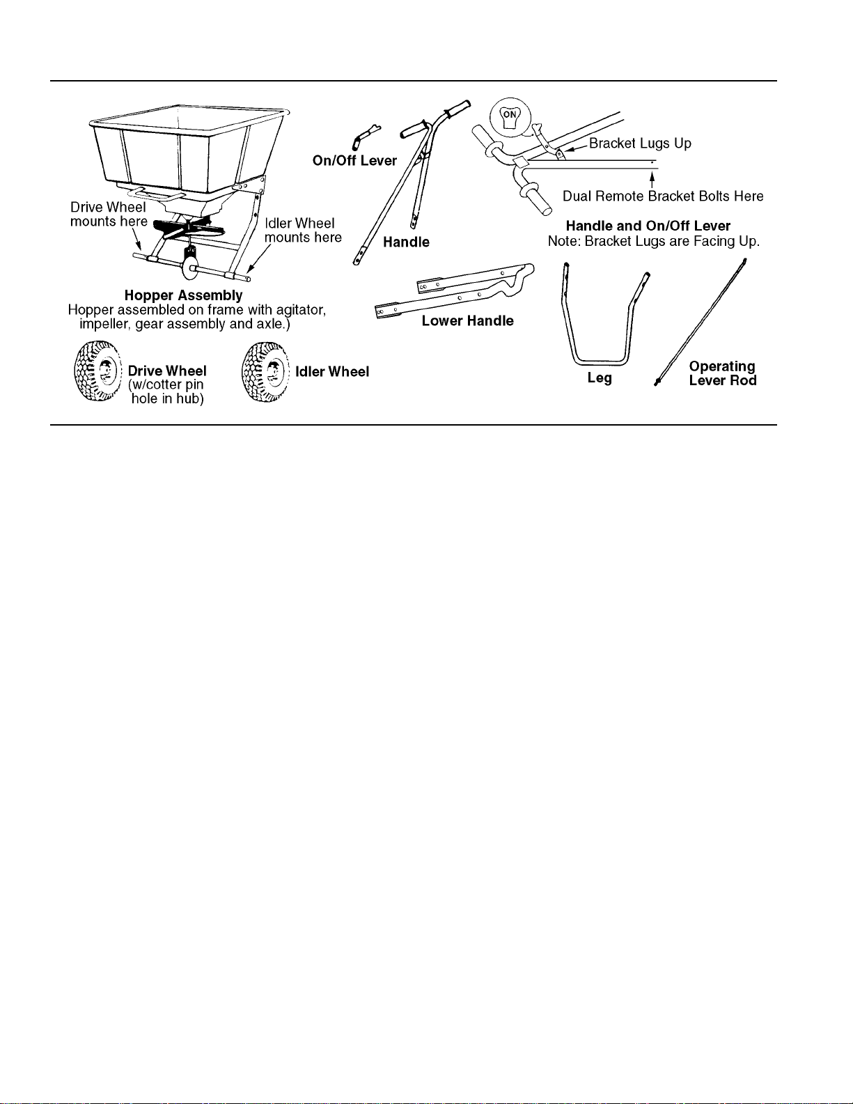
A. Check the spreader discharge holes with the operating lever
in the closed position. If the discharge holes are not fully
closed, thread the upper nut on the operating lever rod fur-
ther up the rod. Tighten the lower locknut and recheck. Re-
peat this procedure until the holes are fully closed.
B. TO ACHIEVE A UNIFORM DISTRIBUTION PATTERN:
The accurate method for checking pattern uniformity is to lay
out shallow boxes or pans in a row on a line perpendicular to
the direction of spreader travel. Eleven boxes or pans, two
inches high placed on one-foot centers will provide accurate
calibration. To conduct the test, begin with the remote and
third hole slide plates completely open and set the calibrat-
ing slide at the suggested approximate setting. Make three
passes over the boxes, pushing the spreader in the same
direction each time.The product caught in each box is then
evaluated to determine the distribution pattern.Weighing the
productineachboxIsthemostaccurate, butasimplermethod
Is to pour the contents of each box into a separate small vial
or bottle.Then set he eleven vials or bottles side-by-side in
order.This makes the pattern variation quite visible.
Toreduce the amount ofdischargeto the rightside (operator's
right) partially close the remote slide plate using the remote
cable lever and repeat the test until the distribution pattern is
uniform.
To reduce the amount of discharge to the left side (operator's
left) loosen the knob and partially close the third hole slide
plate and repeat the test until the distribution pattern is uni-
form.
C. TO ACHIEVE THE CORRECT APPLICATION RATE:
The approximate spreader settings printed on the product
label should only be used as the initial setting for calibration.
Set the calibrating slide at this approximate setting. Using
the collection boxes or pans, make a single pass over them
to determine the effective pattern width.The effective pattern
width is twice (2x) the distance to the point where the rate
drops by one-half the average rate at the center. Example: If
the product In the vials from the center boxes averages two
inches in depth, count out to the vial which has one inch of
product. If this is the fifth vial from the center and the boxes
were on one-foot centers, the effective pattern width is ten
feet (2 x 5 ft.).
Knowing the effective pattern width (ten feet), measure out a
linealdistance to equal 1,000 sq.ft.(10ft.x 100 ft. =1,000sq.
ft.).Weigh 20 Ibs.of product and place it in the spreader hop-
per and spread it over the distance necessary to equal 1,000
sq.ft.(100 ft.).Then weigh the product left in the hopper and
subtract this amount from the amount with which you started.
The result is the application rate for this product in pounds
per 1,000 sq. ft. that your spreader is currently adjusted to
disperse. Adjust the calibrating slide as needed and repeat
this procedure until the correct application rate is achieved.
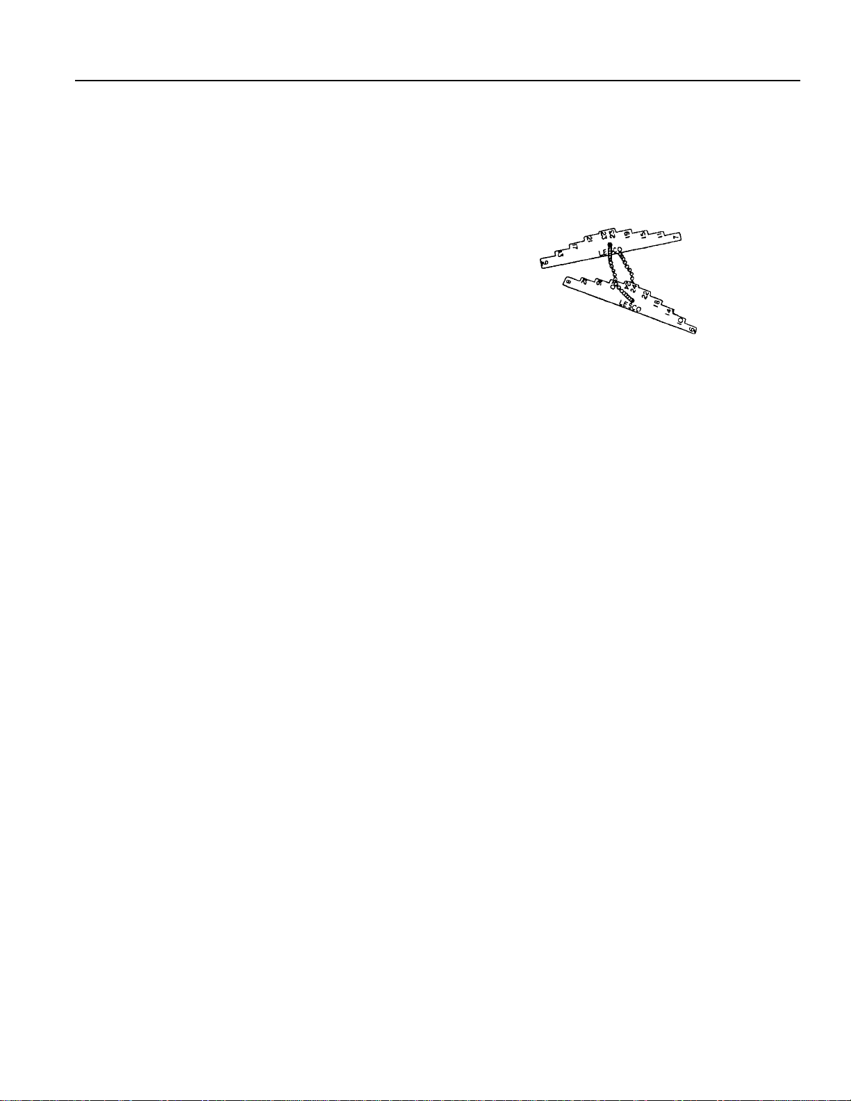
D. TO USETHE LESCO CALIBRATION GAUGES:
The LESCO Calibration Gauges provide a series of “steps”,
numbered in 1/32-inch increments, that will allow you to“fine-
tune” the LESCO Spreader. Once you have calibrated your
LESCO Mark II spreader for the product chosen, open the
operating lever and insert the calibration gauges until you
determine which step fits tightly into one of the open holes in
the hopper bottom. Record that step number for future refer-
ence when using that product.You may choose to set other
LESCO Mark II spreaders for application of the same prod-
uct by adjusting the main slide plate to that calibration gauge
step. This will provide consistent settings for all of your LE-
SCO spreaders.To recalibrate your LESCO Mark II spreader
after a period of use, adjust the calibrating slide to the “S”
position. Open the operating lever and insert the even-num-
bered LESCO Calibration Gauge into one of the open holes
in the hopper bottom. Close the operating lever and let the
main slide plate on the underside of the hopper make con-
tact with the number ten step on the LESCO Calibration
Gauge. Move the calibrating slide back toward the “A” posi-
tion until the bottom of the slide makes contact with the cali-
brating rod. If your spreader is properly adjusted, the cali-
brating window should be pointing at setting“D”on the top of
the calibrating slide. To correct a variance, adjust the cali-
brating window by loosening the machine screws which hold
it.
E. SPREADER OPERATION:
1. Always push the spreader; do not pull.
2. Push the spreader at a consistent speed (approximately 3
m.p.h. is recommended).
3. Always close the operating lever before filling the hopper.
4. Be sure the screen is in place to prevent lumps or paper
scraps from plugging the holes in the hopper bottom.
5. Always start moving forward before opening the operating
lever; close the operating lever before forward motion is
stopped.
6. Hold the handle at a height that will keep the impeller level.
7. Empty the spreader after each use.Wash the spreader thor-
oughly and allow it to dry. Keep the impeller clean.
8. Lubricate all linkages with LESCO 5-Way Spray Lubricant,
LESCO No. 019428. Grease the gears with LESCO general
purpose Gun Grease, LESCO No. 050539.

Gear Set and Controls — Figure 1
3

Gear Set and Controls — Parts List for Figure 1
Ref. LESCO No.
No. No. Description Used
1 030501 Hopper .................................................... 1
2 030423 Machine Screw, #10-24 x 1/2, SS ........... 2
3 070028 Machine Screw, #10-24 x 5/8, SS ......... 15
4 030426 Flat Washer, #10, SS .............................. 3
5 070027 Hex Nut, #10-24 Nylock, SS ................. 10
6 030400 Bracket, Spring and Rod Guide, SS ........ 1
7 030406 Bracket, Calibrating Slide, SS ................. 1
8 018615 Spacer, Nylon .500 x .257 x .500 ............ 1
9 018614 Knob, Calibrating Slide............................ 1
10 060033 Flat Washer, 1/4 SS ................................ 6
11 030433 Calibrating Spring, SS............................. 1
12 060031 Clevis Pin, 1/4 x 1/2, SS.......................... 2
13 060032 Cotter Pin, 3/32 x 1/2, SS........................ 7
14 060073 Lock Washer, 5/16, SS ........................... 1
15 060071 Hex Nut, 5/16-18, SS .............................. 1
16 030408 Lever Rod, SS......................................... 1
17 030398 Bracket, Lever Rod Adjusting, SS ........... 1
18 060072 Hex Nut, 5/16-18 Nylock, SS .................. 1
19 030581 Calibrating Rod, SS................................. 1
20 030397 Bellcrank Pivot, SS.................................. 1
21 030396 Bellcrank Pivot Mount, LH, SS ................ 1
22 030395 Bellcrank Pivot Mount, RH, SS................ 1
23 030392 Remote Slide Plate, SS........................... 1
24 030424 Conduit Clip ............................................ 1
25 030444 Cable, Remote Control............................ 1
26 018628 Flat Washer, 1/4, Nylon........................... 1
27 030427 Knob, Third Hole Slide Plate ................... 1
28 030407 Main Slide Plate, SS ............................... 1
29 030404 Linkage Rod, Slide Plate, SS .................. 1
30 030399 Slide Plate, Third Hole, SS...................... 1
31 030428 Carriage Bolt, #10-24 x 3/8, SS............... 1
32 030440 Guide, Shut Off Plate .............................. 1
33 060069 Roll Pin, 1/8 x 7/8, SS ............................. 1
34 030415 Screw, #10 x 5/8 T-A Hex Slot Hd., SS ... 3
35 030593 Cap, Gear Set ......................................... 1
36 030391 Spreader Axle, SS................................... 1
37 030385 Seal, Housing and Cover ........................ 2
38 030591 Housing, Gear Set .................................. 1
39 030594 Gear........................................................ 1
40 700129 Screw, #6 x 5/8 T-A Pan Hd. Phil., SS .... 6
41 030592 Cover, Gear Set ...................................... 1
42 060019 Roll Pin, 5/32 x 1-1/4, SS ........................ 1
43 030595 Pinion Gear ............................................. 1
44 060022 Roll Pin, 1/8 x 5/8, SS ............................. 1
45 030384 Seal, Gear Set Cap ................................. 1
46 030403 Impeller Shaft, SS ................................... 1
47 030317 Impeller ................................................... 1
48 030322 Agitator Cam, SS .................................... 1
49 060050 Spring Clip .............................................. 1
50 030561 Agitator Arm ............................................ 1
51 005530 Plastic Washer ........................................ 5
52 030393 CalibratingWindow ................................. 1
53 030481 Kit, Impeller and Gear Set
Assembly, Mark II ................................... 1
4
54 030626 Nut 1/4-28 SS ......................................... 2
55 030550 Calibrating Rod Adjuster ......................... 1
56 030580 Lower Calibrating Rod SS ....................... 1
57 090006 USA Decal .............................................. 1
58 032541 Lesco Decal ............................................ 1
59 030537 100# Capacity Decal ............................... 1
60 009941 Chain ...................................................... 1
61 097421 Calibration Gauge "odd".......................... 1
62 097461 Calibration Gauge "even" ........................ 1
63 030532 Carton (Box)
64 030445 Operator's Manual & Parts List ............... 1
Ref. LESCO No.
No. No. Description Used
Table of contents
Other Lesco Spreader manuals
Popular Spreader manuals by other brands

Fisher
Fisher POLY-CASTER 78601 owner's manual

Fayat Group
Fayat Group DYNAPAC S100 operation & maintenance

Art's-Way Manufacturing
Art's-Way Manufacturing X700 Operator's manual & parts list

Ferris
Ferris Pathfinder Series Operator's manual

Herculano
Herculano H2RS9 instruction manual

TurfEx
TurfEx RS7200 Owner's/operator's manual