manuals.online logo
Brands
  1. Home
  2. •
  3. Brands
  4. •
  5. Gandy
  6. •
  7. Spreader
  8. •
  9. Gandy 36T13 User manual

Gandy 36T13 User manual

This manual suits for next models

1

Other Gandy Spreader manuals

Gandy 24H13 User manual

Gandy

Gandy 24H13 User manual

Gandy 24H13 User manual

Gandy

Gandy 24H13 User manual

Gandy 10T Series User manual

Gandy

Gandy 10T Series User manual

Gandy 24H12 User manual

Gandy

Gandy 24H12 User manual

Gandy 36H12 User manual

Gandy

Gandy 36H12 User manual

Gandy 10T Series User manual

Gandy

Gandy 10T Series User manual

Popular Spreader manuals by other brands

Sami ST-1000 PTO user manual

Sami

Sami ST-1000 PTO user manual

PEQUEA GT-100 Operator's manual

PEQUEA

PEQUEA GT-100 Operator's manual

Epoke SKE8 instruction manual

Epoke

Epoke SKE8 instruction manual

GEA EL44 Instruction manual and installation instructions

GEA

GEA EL44 Instruction manual and installation instructions

Boss Snowplow TGS 800 owner's manual

Boss Snowplow

Boss Snowplow TGS 800 owner's manual

Fisher EMERSON 168 Series installation guide

Fisher

Fisher EMERSON 168 Series installation guide

Fisher POLY-CASTER 78601 owner's manual

Fisher

Fisher POLY-CASTER 78601 owner's manual

Fayat Group DYNAPAC S100 operation & maintenance

Fayat Group

Fayat Group DYNAPAC S100 operation & maintenance

Art's-Way Manufacturing X700 Operator's manual & parts list

Art's-Way Manufacturing

Art's-Way Manufacturing X700 Operator's manual & parts list

Ferris Pathfinder Series Operator's manual

Ferris

Ferris Pathfinder Series Operator's manual

Herculano H2RS9 instruction manual

Herculano

Herculano H2RS9 instruction manual

TurfEx RS7200 Owner's/operator's manual

TurfEx

TurfEx RS7200 Owner's/operator's manual

Nogueira RoyalFlow-600 instruction manual

Nogueira

Nogueira RoyalFlow-600 instruction manual

APV ES 100 M1 Classic Original operating instructions

APV

APV ES 100 M1 Classic Original operating instructions

BEFCO TURBO-HOP 301-300 Operator's manual

BEFCO

BEFCO TURBO-HOP 301-300 Operator's manual

H&S 5220 Operation manual

H&S

H&S 5220 Operation manual

Turfware TR460 Operation manual

Turfware

Turfware TR460 Operation manual

Anderson Manufacturing SS-2 Assembly & user manual

Anderson Manufacturing

Anderson Manufacturing SS-2 Assembly & user manual

manuals.online logo
manuals.online logoBrands
  • About & Mission
  • Contact us
  • Privacy Policy
  • Terms and Conditions

Copyright 2025 Manuals.Online. All Rights Reserved.

Page 1 of 17
Parts & Assembly Manual
815 Rice Lake Street, Owatonna, MN 55060
Phone: 800-443-2476 / 507-451 5430
www.gandy.net / Email: sales@gandy.net
Turf Tender®
36T13 (Beginning w/ Serial #153868)
36-inch Variable Rate Spreader
Tow Model w/13-inch Pneumatic Tires and Spread Plate
(All Hardware in Hardware Bag Unless Otherwise Specified)
Carton Containing the Following Parts:
Diagram #1
2836-TB
Page 2 of 17
Rotor Bar Package (for 36” Spreader) Contents:
Diagram #2
2836-RP
Hardware Bag 28-T Contents:
Diagram #3
28-T
Note:
Part numbers C21-0177-020 (Qty-2) is not used in this spreader package.
Page 3 of 17
36” Hopper Assembly Schematic
Diagram #4
2836-A1
Bottom Assembly (28368768) Breakdown:
These parts are part of the Bottom Assembly but can be ordered separately.
Diagram #5
28368768
Page 4 of 17
Assembly Instructions: (All Hardware & Small Parts in Hardware Bag Unless Otherwise Specified)
Please read and review all instructions before starting to assemble.
Minimum tools required.
Pliers, Two 7/16” Wrenches & One 1/2" Wrench
Step# 1 (Unpacking & Rotor Bar Assembly)
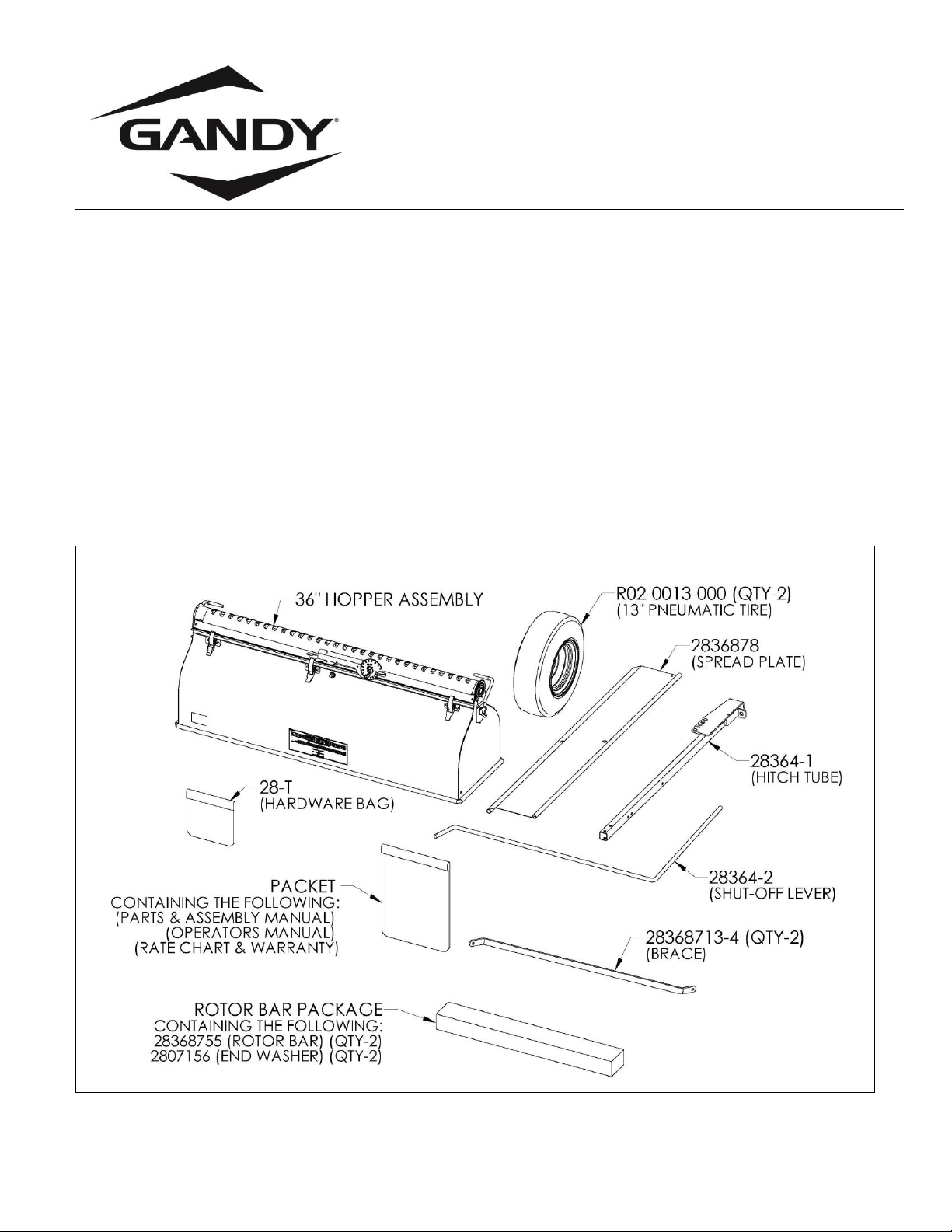
Remove contents from carton and check all parts against page #1 to confirm parts.
Un-wrap rotor bars, making sure one washer stays on each long end of rotor bar. (See Diagram #2 on page #2)
Carefully open the hardware bag and check all parts against page #2, Diagram #3 to confirm all parts.
1.
Note: Lay something down (piece of cardboard or blanket) to protect hopper from being scratched up.
Place hopper upside down with cam gauge facing you.
2.
Un-snap latches on hopper (three each side) and un-hook from bottom assembly.
3.
Remove bottom assembly from hopper by pulling straight up on it.
4.
Remove the 5/16”wing nut and washer from each bearing retainer and remove both bearing retainers.
Save the wing nuts & washer as they will be re-used latter.
5.
Remove both bearings from hopper. (Note: Bearing may fall out when removing bearing retainers.)
6.
Install rotor bars (short end of rotor bar) into center bearing.
7.
Slide bearing onto rotor bar (long end) up to hopper, making sure washer is still on rotor bar.
Repeat for other rotor bar. Make sure center bearing is standing straight up.
8.
Install bottom assembly back onto hopper. Cam gauge will be on same side as the 5/16”threaded stud.
9.
Make sure bearings are pushed into hopper, re-snap all six latches to hold bottom in place.
10.
Re-install left side bearing re-using the 5/16”washer and wing nut to hold bearing retainer in place.
When installing make sure the rod on the bearing retainer is on the opposite side of the cam gauge.
Other bearing retainer will be re installed in the next step.
Diagram #6
2836-A1
Page 5 of 17
Step# 2 (Spread Plate Assembly)
1.
Locate Spread Plate (2836878).
2.
Slide rolled edge (side without bend) of spread plate onto bearing retainer rod as shown in Diagram #7.
3.
Re-install the last bearing retainer to hopper and spread plate re-using the 5/16”washer and wing nut.
3.
Adjust bearing retainers so spread plate can pivot freely. Tighten both 5/16”wing nuts securely.
Diagram #7
2836-A1
Step# 3 (Tire Assembly)
Install tire (R02-0013-000) to rotor bar shaft end using the 3/16 x 1-3/4 clevis pin (C22-0187-090) and
3/32 x 3/4 cotter pin (C20-0093-020). Pin tire to the hole in the rotor bar that is closest to hopper.
Repeat for other tire.
Diagram #8
2836-A1
Page 6 of 17
Step# 4 (Locate the Following Parts & Hardware)
Parts:
Hitch Tube (28364-1)
Shut-Off Lever (28364-2)
Guide Shut-Off Lever (28364-3)
Hardware:
1/4 x 1-1/2 Hex Bolts (C03-0250-061) (Qty-2)
1/4” Washers (C02-0250-020) (Qty-2
1/4” Flange Nuts (C01-0250-030) (Qty-2)
Diagram #9
2836-T1
Page 7 of 17
Step# 5 (Hitch Tube & Shut-Off Lever Assembly)
1.
Insert the angled end of shut-off lever (28364-2) (end with hole) into guide tab on hitch tube as shown
in Diagram #10.
2.
When the angled corner of the shut-off lever hits the guide tab rotate the shut-off lever up towards the
hitch tube until the shut-off lever goes through the guide tab. See diagram #11.
See diagram #12 for in place view.
Diagram #10
Diagram #11
Diagram #12
2836-T2
Page 8 of 17
Step# 6 (Guide Shut-Off Lever Assembly)
1.
Slide the guide shut-off lever (28364-3) over the end of the shut-off lever as shown in Diagram #13.
2.
Slide the guide all the way down the lever and rotate guide around corner as shown in Diagram #14.
Now the two holes in the guide will align with the holes in the hitch tube.
3.
Fasten the guide in place as shown in diagram #15 using the listed hardware & then tighten securely.
Diagram #13
2836-T3
Diagram #14
2836-T3
Diagram #15
2836-T4
Page 9 of 17
Step# 7 (Hitch to Hopper Assembly)
1.
Note: Lay something down (piece of cardboard or blanket) to protect hopper from being scratched up.
Lay hopper on its side so the cam gauge is up & pivot the spread plate down out of the way as shown in
Diagram #16.
2.
Remove the 5/16”flange nut from the stud above and to the right of the cam gauge as shown
in Diagram #16.
3.
Attach the hitch tube with shut-off lever in place to the 5/16” stud & re-use the 5/16”flange nut.
Make sure the end of the shut-off lever goes into the U-notch as shown in Diagram #17.
Do not tighten, leave nut loose.
Diagram #16
Diagram #17
2836-T5
Page 10 of 17
Step #9 (Left Brace to Hitch Assembly)
1.
Locate the TWO braces (28368713-4), TWO 1/4 x 1/2 hex bolts (C03-0250-010), ONE 1/4 x 1-3/4 hex bolt
(C03-0250-070), THREE 1/4" flange nuts (C01-0250-030) and ONE 1/4" washer (C02-0250-020).
2.
Attach one end of the brace to the 1/4" hole in the side of the hopper as shown in Diagram #17 using a
1/4 x 1/2 hex bolt and 1/4" flange nut as shown. Do not tighten bolt.
3.
Attach the other end of the brace to the 1/4” hole in the side of the hitch tube using a 1/4" washer, 1/4 x 1-
3/4 hex bolt and 1/4" flange nut as shown in diagram #18. Do not tighten, leave loose.
Diagram #18
2836-T6