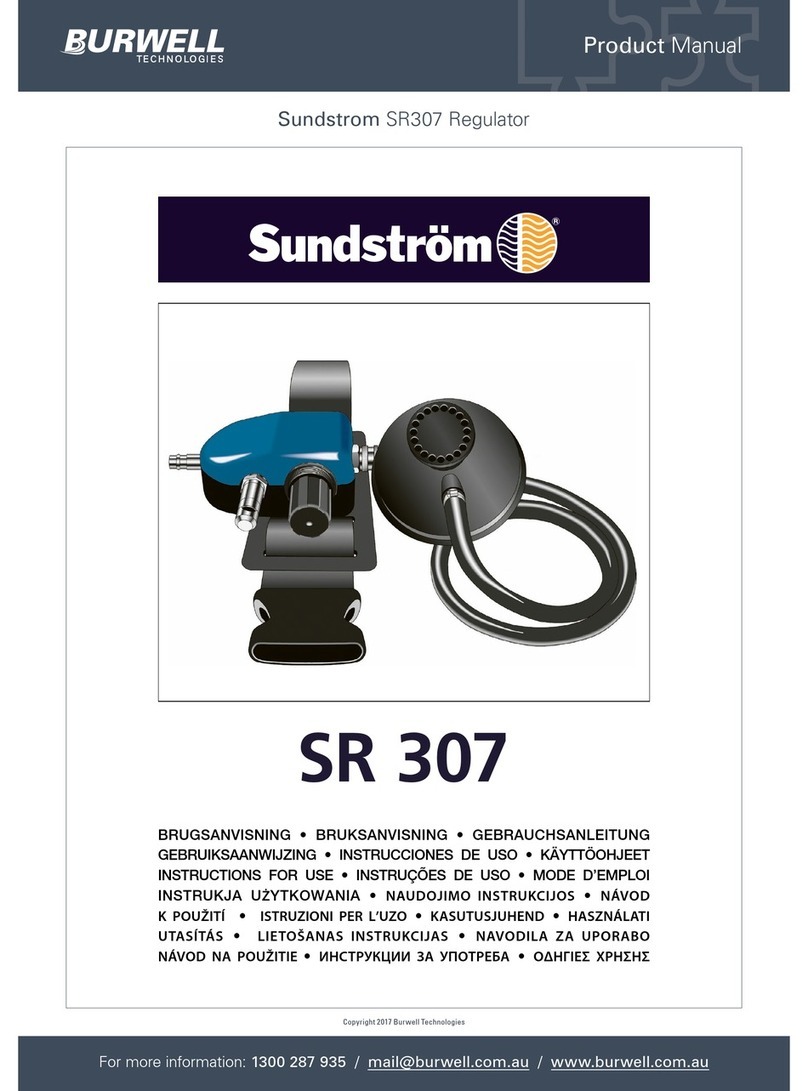
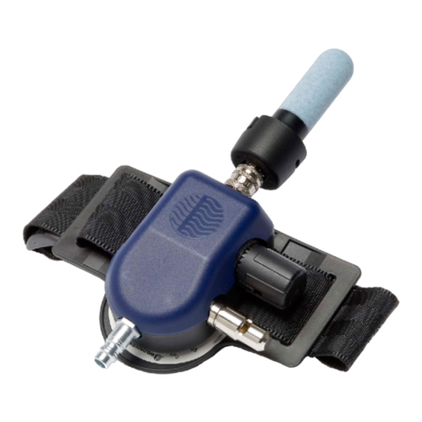
Sundstrom SR 500 User manual

Product Manual
Sundstrom SR500 Regulator
For more information: 1300 287 935 / mail@burwell.com.au / www.burwell.com.au
Copyright 2017 Burwell Technologies
SR 500
BRUGSANVISNING • BRUKSANVISNING • GEBRAUCHSANLEITUNG
GEBRUIKSAANWIJZING • INSTRUCCIONES DE USO • KÄYTTÖOHJEET
INSTRUCTIONS FOR USE • INSTRUÇÕES DE USO • MODE D’EMPLOI
INSTRUKJA UŻYTKOWANIA • NAUDOJIMO INSTRUKCIJOS • NáVOD K
POUžITí ISTRUZIONI PER L’UZO • KASUTUSJUHEND • HASZNáLATI UTASíTáS
LIETOšANAS INSTRUKCIJAS • NAVODILA ZA UPORABO • ИнструкцИИ за
употреба• NáVOD NA POUžITIE • Οδηγίες χρηςης• KULLANIM TALİMATLARI

35
Fan unit SR 500 EN
1. General information
2. Technical specification
3. Use
4. Maintenance
5. Parts list
6. Key to symbols
7. Worn-out products
8. Approvals
1. General information
The SR 500 is a battery-powered fan unit that, together
with filters and head top, is included in the Sundström
fan-assisted respiratory protective device systems
conforming to EN 12941 or EN 12942 and to Sund-
ström Powered Air Purifying Respirator (PAPR) system
conforming to AS/NZS 1716:2012.
Before use, both these user instructions and those for
the filter and head top must be carefully studied.
The fan unit is to be equipped with filters, and the filte-
red air is supplied through a breathing hose to the head
top.
The above-atmospheric pressure then generated pre-
vents pollutants from the surroundings from penetra-
ting into the head top.
Use of a respirator must be part of a respiratory protec-
tion program. For advice see EN 529:2005 or AS/NZS
1715:2009.
The guidance contained in these standards highlights
important aspects of a respiratory protective device
program but does not replace national or local
regulations.
If you feel uncertain about the selection and care of the
equipment, consult your work supervisor or get in
touch with the sales outlet. You are also welcome to get
in touch with the Technical Service Department at
Sundström Safety AB.
1.1 Applications
The SR 500 can be used as an alternative to filter respi-
rators in all situations for which these are recommended.
This applies particularly to work that is hard, warm or of
long-duration.
When selecting filters and head top, the following are
some of the factors that must be taken into account:
• Possible occurrence of explosive atmosphere
• Types of pollutants
• Concentrations
• Work intensity
• Protection requirements in addition to respiratory
protective device
The risk analysis should be carried by a person who has
suitable training and experience in the area.
1.2 System description
Fan unit
The characteristics of the SR 500 are as follows:
• Operating time of up to 13 hours.
• The battery is of lithium ion type that is good for at
least 500 charging cycles.
• The same control is used for starting, stopping and
selection of operating status.
• Display with clear symbols.
• Initiates an alarm by vibration and sound/light signals
in the event of an obstruction in the air flow.
• Equipped with automatic air flow control with
compensation for air pressure and temperature.
• To be used with two filters/combined filters.
• Can be used together with a hood, visor, welding
shield, half mask, full face mask, helmet with visor or
welding shield together with helmet with visor.
Filters
See 3.4
Breathing hose
The breathing hose is not included with the fan unit but
is supplied with the relevant head top.
The breathing hose for half mask and full face mask is
purchased separately.
Head top
The choice of head top depends on the working
environment, work intensity and the required protection
factor. The following head tops are available for the SR
500:
• Class TH3 hood, model number SR 520.
• Class TH3 hood, model number SR 530.
• Class TH3 hood, model number SR 561.
• Class TH3 hood, model number SR 562.
• Class TH3 visor, model number SR 540.
• Class TH3 welding shield, model number SR 590.
• Class TM3 full face mask, model number SR 200.
• Class TM3 half mask, model number SR 900.
• Class TH3 helmet with visor, model number SR 580.
• Class TH3 weldning shield together with helmet with
visor, model number SR 584/SR 580.
• Class TH3 gold-plated shield together with helmet
with visor, model number SR 587/SR 580.
• Class TH3 shield 2/3, EN 3 together with helmet with
visor, model number SR 588-1/SR 580.
• Class TH3 shield 2/3, EN 5 together with helmet with
visor, model number SR 588-2/SR 580.
1.3 Warnings/limitations
Warnings
The equipment must not be used
• In the power-off state. In this abnormal situation a
rapid build-up of carbon dioxide and depletion of
oxygen may occur in the head top and no protection
is given.
• If the surrounding air does not have a normal oxygen
content.
• If the pollutants are unknown.
• In environments that are immediately dangerous to
life and health (IDLH).
• With oxygen or oxygen-enriched air.
• If you find it difficult to breathe.
• If you can smell or taste the pollutants.
• If you experience dizziness, nausea or other
discomfort.
Limitations
• The SR 500 must always be used with two particle
filters or two combined filters or a combination of
two gas filters of the same type and two particle
filters.
Sundstrom SR500 Regulator
2 of 17For more information / 1300 287 935 mail@burwell.com.au / www.burwell.com.au

36
• If the user is exposed to very high work intensity, a
partial vacuum may occur in the head top during the
inhalation phase, which may involve the risk of
leakage into the head top.
• The protection factor may be reduced if the
equipment is used in surroundings in which high
wind speeds occur.
• Be aware that the breathing hose might make a loop
and get caught up by something in your
surrounding.
• Never lift or carry the equipment by the breathing
hose.
• The filters must not be fitted directly to the head top.
• Only use Sundström filters.
• The user should take care not to confuse the
markings on a filter to standards other than EN 12941
and EN 12942 with classification of the SR 500 fan
unit when used with this filter.
2. Technical specification
Air flow rate
During normal operation, the air flow rate is at least 175
l/min, which is the manufacturer’s recommended mini-
mum flow rate or MMDF.
On boosted operation, the air flow rate is 240 l/min.
The automatic flow control system of the fan unit main-
tains these flows constant throughout the operating
time.
Batteries
STD, Standard, 14.8 V, 2.2 Ah, lithium-ion.
HD, Heavy Duty, 14.8 V, 3.6 Ah, lithium-ion.
• The charging time for the STD battery is about 1.5 h.
• The charging time for the HD battery is about 2 h.
• The cycling life is about 500 full cycles.
• The battery do not need to be discharged before it is
charged.
Operating times
The operating times may vary with the temperature, and
the condition of the battery and filters.
The table below gives the expected operating times un-
der ideal conditions.
STD HD Filter Air flow rate Expected
operating
• P3 R (PAPR-P3) 175 l/min 8 h/7 h*
• P3 R (PAPR-P3) 175 l/min 13 h/12 h*
• P3 R (PAPR-P3) 240 l/min 8 h/7 h*
• A1BE2K1P3 R 175 l/min 5 h/4 h*
(PAPR-A1BE2K1-P3)
• A1BE2K1P3 R 175 l/min 8,5 h/7,5 h*
(PAPR-A1BE2K1-P3)
• A1BE2K1P3 R 240 l/min 5 h/4 h*
(PAPR-A1BE2K1-P3)
*SR 900 + SR 951/SR 952
Shelf life
The equipment has a shelf life of 5 years from the date
of manufacture. However, note that the battery must be
charged at least once a year.
Pressure and temperature range
• Storage temperature. Fig. 3.
• Service conditions. Fig. 4.
3. Use
3.1 Unpacking
Check that the equipment is complete in accordance
with the packing list and has not been damaged in
transit.
3.2 Packing list
Fig. 1.
1. Fan unit SR 500, bare
2. Battery, STD
3. Battery charger SR 513
4. Belt SR 508
5. P3 R Particle filter SR 510, 2x
6. Filter adapters SR 511, 2x
7. Pre-filters SR 221, 10x
8. Pre-filter holders SR 512, 2x
9. Flow meter SR 356
10. User instructions
11. Cleaning tissue SR 5226
12. Plug kit
3.3 Battery
New batteries must be charged before they are used for
the first time. See 3.5 Assembly.
3.4 Filters
The choice of filters/combined filters depends on factors
such as the type and concentration of pollutants. The
fan unit may be used with only particle filters or with a
combination of particle filters and gas filters.
The following filters are available for the SR 500:
• Particle filter P3 R (PAPR-P3), model number SR
510. Used with an adapter. Two filters are supplied
with the fan. Can be combined with a gas filter.
• Particle filter P3 R (PAPR-P3), model number SR
710. Provided with a thread, and there is no need for
an adapter. Cannot be combined with a gas filter.
• Gas filter A2 (PAPR-A2), model number SR 518.
Shall be combined with a particle filter.
• Gas filter ABE1 (PAPR-ABE1), model number SR
515. Shall be combined with a particle filter.
• Gas filter A1BE2K1 (PAPR-A1BE2K1), model number
SR 597. Shall be combined with a particle filter.
• Combined filter A1BE2K1-Hg-P3 R (PAPRA1BE2K1-
Hg-P3), model number SR 599.
Note!
• The filters used must be of the same type, i.e. two
P3 R (PAPR-P3) or two A2P3 R (PAPR-P3), etc.
• When filters are changed, both filters/combined
filters must be changed at the same time.
• The particle filter must always be used - either
separately or in combination with a gas filter.
Particle filter P3 R (PAPR-P3)
Sundström markets only particle filters of the highest
class P3 R (PAPR-P3). Two models are available for fan
SR 500, i.e. SR 510 and SR 710. The filters provide pro-
tection against all types of particles, both solid and li-
quid. The SR 510 can be used separately or combined
with a gas filter. The SR 710 cannot be combined with a
gas filter. The particle filters can be used with the same
pre-filter holder as the one used with the Sundström
half- and full face masks. In these cases, the standard
pre-filter holder of the fan is excluded. See 5. Parts list.
Sundstrom SR500 Regulator
3 of 17For more information / 1300 287 935 mail@burwell.com.au / www.burwell.com.au

37
Gas filters A, B, E, K, Hg
A protects against organic gases and vapours, e.g. sol-
vents, with a boiling point of more than +65 °C.
B protects against inorganic gases and vapours, e.g.
chlorine, hydrogen sulphide and hydrogen cyanide.
E protects against acidic gases and vapours, such as
sulphur dioxide and hydrogen fluoride.
K protects against ammonia and certain amines, e.g.
ethylene diamine.
Hg provides protection against mercury vapour. War-
ning! Maximum use time 50 hours.
The gas filters must always be combined with particle
filters P3 R (PAPR-P3). Press the filters together so that
the arrows on the particle filter point towards the gas fil-
ter. Fig. 21.
Combined filter SR 599, A1BE2K1-Hg-P3 R,
(PAPR-A1BE2K1-Hg-P3)
Protects against ABEK-P3 R (PAPR-ABEK-P3) pollu-
tions as described above and in addition against Hg,
mercury vapour. When used to protect against mercury
vapour the period of use is limited to 50 hours.
Pre-filter
The pre-filter protects the main filter against excessively
fast clogging. Fit in the pre-filter holder. The pre-filter hol-
ders protects also the main filters against handling
damage.
Note! The pre-filter can serve only as a pre-filter. It can
never replace the particle filter.
3.5 Assembly
a) Battery
On delivery, the battery fitted in the fan unit is provided
with protective tape over the terminals. Remove the bat-
tery and remove the tape.
• Remove and charge the battery. Fig. 5, 6, 7, 8.
The charger carries out charging automatically in three
stages.
Fig. 9.
1. Orange LED.
2. Yellow LED.
3. Green LED.
• When charging has been completed, pull the plug
out of the socket before separating the battery from
the charger.
• Push the battery back into the battery compartment.
Check that the battery has been pushed in as far as
it will go and that its lock is operative.
Warning!
• Always recharge the batter y before it has become ful-
ly discharged.
• The charger may be used only for charging the batte-
ries for the SR 500.
• The battery may be charged only with a genuine
Sundström charger.
• The charger is designed only for use indoors.
• The charger must not be covered while it is in use.
• The charger must be protected against moisture.
• Never short circuit the battery.
• Never try to dismantle the battery.
• Never expose the battery to an open flame. There is
risk of explosion/fire.
b) Belt
• Assemble the belt. Fig. 10, 11, 12.
Note! Study the illustrations carefully to ensure that the
belt will not end up upside down or back to front.
c) Breathing hose
Read carefully the user instructions accompanying the
head top.
Full face mask SR 200:
• Assemble the hose between full face mask SR 200
and fan unit SR 500. Fig. 13, 14, 15.
• Check that the hose is firmly secured.
Half mask SR 900:
• Assemble the hose between half mask SR 900 and
fan unit SR 500. Fig. 16, 17.
• Check that the hose is firmly secured.
d) Particle filters/combined filters
Two filters or combined filters of the same type and class
must always be used at the same time.
1. Particle filter SR 510
• Check that the gaskets in the filter mounting of the fan
unit are in place and are in good condition. Fig. 18.
• Snap the particle filter onto the filter adapter. Do not
press onto the centre of the filter - it might damage
the filter paper. Fig. 19.
• Screw the adapter into the filter mounting so far that
the adapter will be in contact with the gasket. Then
turn it about 1/8 turn further in order to ensure a good
seal. Fig. 20.
• Fit one pre-filter into the pre-filter holder. Fig. 21.
• Press the pre-filter holder onto the particle filter.
Fig. 22.
2. Particle filter SR 710
• Check that the gaskets in the filter mounting of the fan
unit are in place and are in good condition. Fig. 18.
• Screw the filter into the filter mounting so far that the
adapter will be in contact with the gasket. Then turn it
about 1/8 of a turn further in order to ensure a good
seal. Fig. 20.
• Fit one pre-filter into the pre-filter holder. Fig. 21.
• Press the pre-filter holder onto the particle filter.
Fig. 22.
3. Combined filters
• Check that the gaskets in the filter mounting of the fan
unit are in place and are in good condition. Fig. 18.
• Snap the particle filter onto the gas filter. The arrows
on the particle filter must point towards the gas filter.
Do not press onto the centre of the filter - it might da-
mage the filter paper. Fig. 19.
• Screw the combined filter into the filter mounting until
it is in contact with the gasket. Then turn it about 1/8
turn further to ensure a good seal. Fig. 24.
• Fit a pre-filter into the pre-filter holder. Fig. 21.
• Press the pre-filter holder onto the combined filter.
Fig. 25.
Filter SR 599 is a combined gas filter and particle filter
and is screwed directly into the filter mounting of the fan.
Proceed as described above.
Sundstrom SR500 Regulator
4 of 17For more information / 1300 287 935 mail@burwell.com.au / www.burwell.com.au

38
e) Plug kit
The Plug kit is used for cleaning or decontamination of
the fan unit and prevents dir t and water from entering the
fan housing.
Disconnect the breathing hose and the filters and install
the plugs. Fig. 42.
3.6 Operation/performance
Start/Switch off
• Start the fan unit by pressing the control button
once. Fig. 26.
• The symbols on the display will light up, the sound
signal will sound and the vibrator will vibrate. Fig. 27.
• The battery symbol on the display indicates the
battery capacity.
o Lights green: > 70 %
o Flashing green: 50-70 %
o Lights yellow: 20-50 %
o Flashing red: < 20 %
• The fan unit starts in normal operating status (175 l/
min).
Switch between normal and boosted operating
status (240 l/min) with the control button.
• To switch off the fan unit, keep the control button
depressed for about two seconds.
Display symbols
Fig. 28
a) Battery: Indicate the battery capacity at start and
when the battery capacity is low.
b) Small fan: Lights up with a green light during normal
operation.
c) Bigger fan: Lights up with a green light during
boosted operation.
d) Warning triangle: Lights up with a red light if the air
flow are obstructed or if the filters are clogged.
Warning system/Alarm signals
• In the event of air flow obstructions
o A pulsating sound signal will be heard.
o The built-in vibrator will be activated.
o The red warning triangle of the display will flash.
Action: Immediately interrupt the work, leave the area,
and inspect the equipment.
• If the particle filters are clogged
o A continuous sound signal will be heard for five
seconds.
o The built-in vibrator will be activated for five
seconds.
o The red warning triangle in the display will flash.
The warning triangle will flash continuously, whereas the
sound signal and the vibrator will be repeated at inter vals
of 80 seconds.
Action: Immediately interrupt the work, leave the area
and change the filter.
Note! No signal is activated when the gas filters are sa-
turated. For particulars of changing the gas filters, see
under 3.4 Filters and the user instructions supplied with
the filters.
• If the battery capacity is lower than 5 %
o A sound signal will be repeated twice at intervals
of two seconds.
o The built-in vibrator will be activated twice at in-
tervals of two seconds.
o The battery symbol of the display will flash red.
The battery symbol will flash continuously, whereas the
other signals are repeated at intervals of 30 seconds un-
til about one minute remains before the batter y would be
fully discharged. The sound signal then changes to an
intermittent signal.
Action: Immediately interrupt the work, leave the area
and change/charge the battery.
3.7 Performance check
The performance check should be checked on every
occasion before the fan unit is used.
Check of the minimum flow - MMDF
• Check that the fan unit is complete, correctly moun-
ted, thoroughly cleaned and undamaged.
• Start the fan unit.
• Place the head-top in the flow-meter.
o SR 550 PU and SR 951 PU breathing hose:
Grip the lower part of the bag to seal around the
breathing hose.
o SR 551 Rubber and SR 952 PU breathing hose:
Grip the lower part of the bag to seal around the
upper attachment of the breathing hose. Fig. 29.
Note! You must not grip around the rubber hose
itself as this would either obstruct the air flow or
cause failure to achieve a proper seal.
• Grip the flow meter tube with the other hand so that
the tube points vertically upwards from the bag.
Fig. 30.
• Read the position of the ball in the tube. This should
hover at a level with or slightly above the upper
marking on the tube, (175 l/min). Fig. 31.
If minimum flow is not achieved, check that
- the flow meter is held upright,
- the ball moves freely,
- the bag seals well around the hose.
Checking the alarms
The equipment is designed to provide a warning if the air
flow is obstructed.
• Provoke an air flow stoppage by gripping the top part
of the bag or by shutting off the flow meter outlet.
Fig. 32.
• The fan unit should then initiate alarms by sound, light
signals and vibrations.
• If the air is again allowed to flow, the alarm signals will
automatically cease after 10-15 seconds.
3.8 Putting the equipment on
After the filters have been fitted, a performance check
has been carried out and the head top has been con-
nected, the equipment can be put on. Before putting it
on, read the user instructions for the head top.
• Take the fan unit on and adjust the belt so that the fan
unit is firmly and comfortably secured at the back of
your waist. Fig. 33.
• Start the fan unit.
• Put the head top on.
• Make sure that the breathing hose runs along your
back and is not twisted. Fig. 33.
Note that when a full face mask is used, the hose should
run along your waist and up along the chest. Fig. 34.
When a half mask is used, the hose should run along
your back and over your shoulders. Hose SR 951, see
fig. 35. Hose SR 952, see fig. 36.
Sundstrom SR500 Regulator
5 of 17For more information / 1300 287 935 mail@burwell.com.au / www.burwell.com.au

39
3.9 Taking the equipment off
Leave the polluted area before taking the equipment off.
• Take off the head top.
• Switch off the fan unit.
• Release the belt and remove the fan unit.
After use, the equipment must be cleaned and inspected.
See 4 Maintenance.
4. Maintenance
The person who is responsible for cleaning and mainte-
nance of the equipment must have suitable training and
be well acquainted with work of this type.
4.1 Cleaning
Sundström cleaning tissue SR 5226 are recommended
for daily care. At more thorough cleaning or decontami-
nation - proceed as follows:
• Assemble the plug kit. See 3.5 e.
• Use a soft brush or sponge moistened with a solution
of water and dishwashing detergent or the like.
• Rinse the equipment and leave it to dry.
N.B. Never use a solvent for cleaning.
4.2 Storage
After cleaning, store the equipment in a dry and clean
place at room temperature. Avoid exposing it to direct
sunlight. The flow meter can be turned inside out and
can be used as a storage bag for the head top.
4.3 Maintenance schedule
The following schedule shows the recommended mini-
mum maintenance procedures required in order to en-
sure that the equipment is always in functional
condition.
Before After Annually
use use
Visual inspection ••
Performance check ••
Cleaning •
Change of fan gaskets •
4.4 Spare parts
Always use genuine Sundström parts. Do not modif y the
equipment. The use of non-genuine parts or modifica-
tion of the equipment may reduce the protective function
and put at risk the approvals received by the product.
4.4.1 To change the particle filters/
gas filters/combined filters
Change the particle filters at the latest when they are
clogged. The fan senses when this has occurred and
provides a warning as described in 3.6 under the
heading Operation/performance. The gas filters should
preferably be changed in accordance with a predetermi-
ned schedule. If no measurements are made on site, the
gas filters should be changed once a week or more fre-
quently if the pollutants can be smelt or tasted in the
head top.
Bear in mind that both filters/combined filters must be
changed at the same time and must be of the same type
and class. Proceed as follows:
• Switch off the fan unit.
• Unscrew the filter/combined filter.
• Release the pre-filter holder. Fig. 37.
• Change the pre-filter in its holder. Clean as
necessary.
• To release the particle filter SR 510 from the
adapter, proceed as follows:
o Grip the filter with one hand.
o Place the thumb of the other hand on the under-
side of the adapter at the semicircular gap.
Fig. 38.
o Then prise out the filter. Fig. 39.
• To release the particle filter SR 510 from the gas
filter, proceed as follows:
o Grip the gas filter with one hand.
o Insert a coin or some other flat object, e.g. the fil-
ter adapter, in the joint between the particle and
gas filters.
o Then prise out the filter. Fig. 40.
•Fit new filters/combined filters. See 3.5 d.
4.4.2 To change the gaskets
The gaskets in the filter mountings of the fan unit prevent
polluted air being drawn into the fan unit. They must be
changed once a year or more frequently if wear or age-
ing is detected. Proceed as follows:
• Switch off the fan unit.
• Screw out the filters.
• The gasket has a groove all round and is fitted on a
flange below the threads in the filter mounting. Fig. 41.
• Remove the old gasket.
• Fit the new gasket onto the flange. Check that the
gasket is in place all round.
5. Parts list
Fig. 2.
Item Part Ordering No.
No.
1. Hood SR 561 H06-5012
2. Hood SR 562 H 0 6 -5112
3. Hood SR 520 M/L H06-0212
3. Hood SR 520 S/M H06-0312
4. Hood SR 530 H 06-0412
5. Face shield SR 540 H06-0512
6. Full face mask SR 200, PC visor H01-1212
6. Full face mask SR 200, glass visor H01-1312
7. Half mask SR 900 S H01-3012
7. Half mask SR 900 M H 01-3112
7. Half mask SR 900 L H01-3212
8. Welding shield SR 590 H06-4012
9. Helmet with visor SR 580 H06-8012
10. Welding shield/Helmet with visor
SR 584/SR 580 H06-8310
11. Hose SR 550 T01-1216
11. Hose SR 551 T01-1218
12. Hose SR 951 T01-3003
13. Twin hose SR 952 R01-3009
14. Gold-plated shield SR 587 R06-0824
15. Shield 2/3, EN 3 SR 588-1 R06-0825
15. Shield 2/3, EN 5 SR 588-2 R06-0826
16. Flow meter SR 356 R03-0346
17. Steel net disc SR 336 T01-2001
18. Asbestos kit SR 509 T06-0105
19. Storage bag SR 505 T06-0102
20. STD Standard battery, 2.2 Ah R06-0108
21. HD battery, 3.6 Ah T06-0101
21. Battery charger SR 513 R06-0103
22. Belt SR 508 R06-0101
Sundstrom SR500 Regulator
6 of 17For more information / 1300 287 935 mail@burwell.com.au / www.burwell.com.au

40
22. Rubber belt SR 504 T06-0104
23. Leather belt SR 503 T06-0103
24. Harness SR 552 T06-0116
25. Fan unit SR 500, bare R 0 6 - 0110
26. Gasket to fan unit R06-0107
27. Pre-filter holder SR 512 R06-0106
28. Pre-filter SR 221 H02-0312
29. Particle filter P3 R, SR 510 H02-1312
30. Filter adapter SR 511 R06-0105
31. Pre-filter holder SR 5153 R01-0604
32. Particle filter P3 R, SR 710 H02-1512
33. Gas filter A2, SR 518 H02-7012
34. Gas filter ABE1, SR 515 H0 2-7112
35. Gas filter A1BE2K1, SR 597 H02-7212
36. Combined filter A1BE2K1-Hg-P3 R,
SR 599 H02-7312
37. Splash cover SR 514 T0 6 - 0114
38. Plug kit R06-0703
6.Key to symbols
Recycling symbol
See user instructions
Not with ordinary waste
CE approved by
INSPEC Certification Services Ltd.
Insulation class 2
Pressure and temperature compensated
7. Worn-out products
The fan unit contains a circuit board with electronic
components, a small proportion of which comprise toxic
substances. The battery contains no mercury, cadmium
or lead, and is therefore not regarded as environmentally
harmful waste. The plastic parts are marked with the
material code. For proper handling, collection and recy-
cling, worn-out fans should be handed in to a recycling
centre. Contact the local authorities for information on
the location of your nearest recycling centre.
Recycle in accordance with local regulations. Proper re-
cycling of the product contributes to efficient use of the
natural resources.
8. Approvals
• The SR 500 in combination with face shield SR 540,
welding shield SR 590, helmet with visor SR 580, hel-
met with visor SR 580 with welding shield SR 584,
hoods SR 520, SR 530, SR 561 or SR 562 is appro-
ved in accordance with EN 12941, class TH3.
• The SR 500 in combination with full face mask SR
200 or half mask SR 900 is approved in accordance
with EN 12942, class TM3.
• The SR 500 conforms to the requirements of EN
61000-6-3 Emission and EN 61000-6-2 Immunity,
which makes the fan conform to EMC Directive
2004/108/EC..
• The electronics ingress protection is approved in IP
classification IP67 in accordance with IEC/EN 60529.
The EC type approval certificate has been issued by No-
tified Body No. 0194. For address, see back-cover.
Australian StandardsMark
The fan SR 500 is tested and certified to comply to
AS/NZS 1716:2012. The StandardsMark is issued
under licence by SAI Global Certification Services Pty
Limited Lic No.766 (ACN 108 716 669) (“SAI Global”).
Sundstrom SR500 Regulator
7 of 17For more information / 1300 287 935 mail@burwell.com.au / www.burwell.com.au

139
9
2
3
14
756
1
11 10
8
12
Sundstrom SR500 Regulator
8 of 17For more information / 1300 287 935 mail@burwell.com.au / www.burwell.com.au

140
3
2
14
5
16
17 18
15
14
19
20
21
23
26
25
37
38
22 24
68
11
910
29 31 33 35
36
3432
30
28
27
2
7
13
12
Sundstrom SR500 Regulator
9 of 17For more information / 1300 287 935 mail@burwell.com.au / www.burwell.com.au

141
5 6
8
100V-240V
50-60 Hz
7
34
-20°C - +40°C
< RH 90%
-10°C - +55°C
< RH 90%
600 hPa - 1200 hPa
Sundstrom SR500 Regulator
10 of 17For more information / 1300 287 935 mail@burwell.com.au / www.burwell.com.au

142
80 %
1 2 3
100 %
910
11 12
13 14
2
1
Sundstrom SR500 Regulator
11 of 17For more information / 1300 287 935 mail@burwell.com.au / www.burwell.com.au

143
19
18
15 16
17
2
1
¼
2
1
+ max 15°
SR 951
Sundstrom SR500 Regulator
12 of 17For more information / 1300 287 935 mail@burwell.com.au / www.burwell.com.au

144
23
22
2120
Sundstrom SR500 Regulator
13 of 17For more information / 1300 287 935 mail@burwell.com.au / www.burwell.com.au

145
2524
28 ABC
D
26 27
Sundstrom SR500 Regulator
14 of 17For more information / 1300 287 935 mail@burwell.com.au / www.burwell.com.au

146
33
34
175 l/min
30
31 32
25
29
35 36
Sundstrom SR500 Regulator
15 of 17For more information / 1300 287 935 mail@burwell.com.au / www.burwell.com.au

147
37 38
39 40
41 42
Sundstrom SR500 Regulator
16 of 17For more information / 1300 287 935 mail@burwell.com.au / www.burwell.com.au

L67-0110 Rev 09 20161007
The fan unit SR 500 is manufactured within a quality
management system accepted by
Notified Body 0194: INSPEC International Ltd.
Certification Services, 56 Leslie Hough way,
Salford, M6 6 AJ, England
Sundström Safety AB
SE-341 50 Lagan • Sweden
Tel: +46 10 484 87 00
E-mail: info@srsafety.se www.srsafety.com
Sundstrom SR500 Regulator
17 of 17For more information / 1300 287 935 mail@burwell.com.au / www.burwell.com.au
Other manuals for SR 500
7
Table of contents
Other Sundstrom Controllers manuals
Popular Controllers manuals by other brands

Dell
Dell PowerEdge Series Removing and Installing the Battery and Battery Cable

Johnson Controls
Johnson Controls Metasys MS-FEU1610-0U installation instructions

National Instruments
National Instruments RMC-8354 installation guide

IAI
IAI ROBO CYLINDER RCM-P operating manual

okii
okii MC1 quick guide

Magnimage
Magnimage LED-F706 user manual