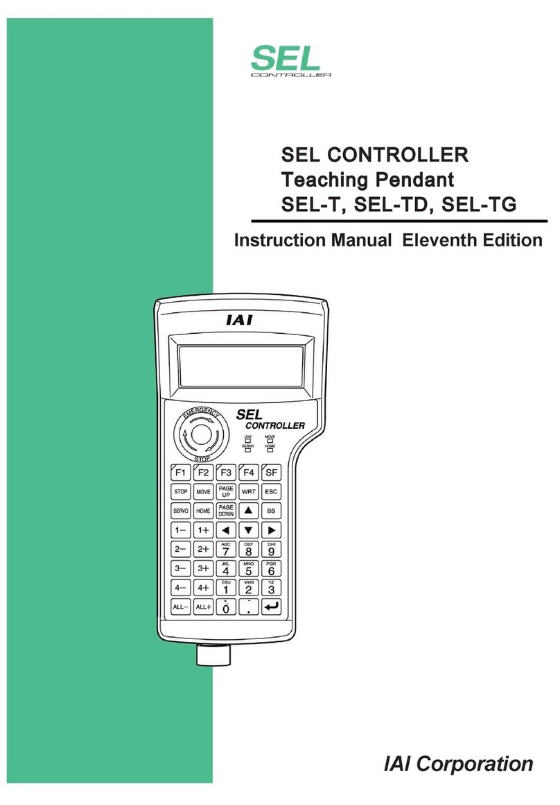
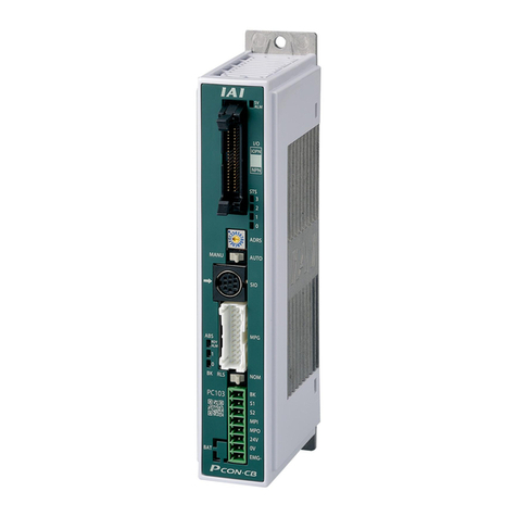
IAI ROBO CYLINDER RCM-P User manual

Robo Cylinder
Data Input Pendant
RCM-P
Operating Manual Second edition
IAI America Inc.


CAUTION
Disconnection of the RC Data Input Pendant from the
PCON/ACON/SCON/ERC2 Controller
* After disconnecting the RC Data Input Pendant from the PCON/ACON/SCON controller with the
AUTO/MANU switch, always turn the AUTO/MANU switch to AUTO.
* For the PCON/ACON/ERC2 controller without AUTO/MANU switch, always set the TP Operation Mode to
“Monitor 2” before disconnecting the RC Data Input Pendant from the controller.
(Refer to “8.10 TP Operation Mode.”)
(Note) When the controller is set by connecting the RC Data Input Pendant to ERC2, the conditions
shown below occur.
When the controller is set by connecting the RC Data Input Pendant to the gateway unit/SIO
converter, the conditions shown below occur.
●If the RC Data Input Pendant is disconnected while the setting of “Teach 1”or “Teach 2”
remains, I/O will become invalid and control from PLC will become impossible.
●If the RC Data Input Pendant is disconnected while the setting of “Monitor 1”remains, the
maximum speed will become the safety speed set for the parameter regardless of a command
from PLC.


Support Models
Versions of the RC Data Input Pendant RCM-P which have started support for each model are as follows.
Table 1 List of Support Models
Model Name Support Started Version
RCP *1V1.00
RCS *1V1.00
E-Con *1V1.30
RCP2 *1V1.63
ERC *1V1.63
ERC2 V2.00
PCON V2.00
ACON V2.00
SCON V2.00
*1: This RC Data Input Pendant also supports the RCP, RCS,
E-Con, RCP2, and ERC controllers.
* Confirm the connected model and version of this application (8.1 Initial Screen During Power-UP).
If any unsupported model is connected, it may operate unexpectedly.
* The software reset function is effective for models corresponding to 1.63 or later of the support started
version.
* ERC2, PCON, ACON, SCON, or ROBONET cannot be used bylinking to any model of those shown in *1.
ROBONET V2.08

Table of Contents
1. Foreword.................................................................................................................................................... 1
2. Before You Begin....................................................................................................................................... 1
3. Safety Precautions..................................................................................................................................... 2
4. Warranty .................................................................................................................................................... 3
5. Application Environment ............................................................................................................................ 5
6. RC Data Input Pendant Functions and Specifications................................................................................ 5
6-1 Specifications...................................................................................................................................... 5
6-2 External View ...................................................................................................................................... 6
6-3 Description of Each Part ..................................................................................................................... 7
7. Connection With the Controller .................................................................................................................. 9
7-1 Connection with the RC Data Input Pendant ...................................................................................... 9
7-2 How to Disengage the RC Data Input Pendant................................................................................... 9
8. Operation ................................................................................................................................................. 10
8-1 Initial Screen During Power - UP ...................................................................................................... 12
8-2 Controller Selection (when using multiple units) ............................................................................... 13
8-3 Operation Mode Selection ................................................................................................................ 14
8-4 Edit/Teach......................................................................................................................................... 16
8-4-1 Edit/Teach Screen ..................................................................................................................... 16
8.4.2 Position Data Table Contents for PCON, ACON, SCON, and ERC2......................................... 19
8-4-3 Position Data Table Contents for RCP, RCS, E-Con, and ERC ................................................ 25
8-4-4 Data Input .................................................................................................................................. 27
8-4-5 Clear • All Clear ......................................................................................................................... 33
8-4-6 Data Modification................................................................................................................................ 36
8-5 Monitor.............................................................................................................................................. 37
8-6 Error List ........................................................................................................................................... 39
8-7 User Parameter................................................................................................................................. 41
8-8 Software reset after user parameters are changed........................................................................... 45
8-9 User Adjustment ............................................................................................................................... 46
8-9-1 Pause, servo ON input enable and disable setting, axis number setting ................................... 46
8-9-2 Software Reset .......................................................................................................................... 48
8-9-3 Error List Clear........................................................................................................................... 49
8-10 TP Operation Mode........................................................................................................................... 50
8-11 End ................................................................................................................................................... 51
4-1 Warranty Period................................................................................................................................... 3
4-2 Scope of Warranty .............................................................................................................................. 3
4-3 Honoring the Warranty ........................................................................................................................ 3
4-4 Limited Liability .................................................................................................................................... 3
4-5 Conditions of Conformance with Applicable Standards/Regulations, Etc., and Applications................ 4
4-6 Limited Liability .................................................................................................................................... 4
* Appendix....................................................................................................................................................... 62
Parameter (factory-installed) initializing method.............................................................................................. 62
RC Data Input pendant error table .................................................................................................................. 64
9. Message Area .......................................................................................................................................... 52
9-1 Warning Label Error (Code No. 000h – 07Fh) .................................................................................. 52
9-2 RC Data Input Pendant Message Level Error.................................................................................. 53
9-3 Controller Error ................................................................................................................................. 53


1
1. Foreword
Thank you very much for purchasing the RC Data Input Pendant (RCA-P) for the Robo Cylinder Controller.
Without knowing beforehand how to correctly use or operate the RC Data Input Pendant, not only will the user
be unable to take full advantage of all the functions built into this product but the user might also inadvertently
cause damage to the Controller or shorten its life. Please carefully read this manual as well as other manuals
pertaining to the product to acquire an understanding of the proper method of handling and operating the
controller. Keep this manual handy so that you can refer to the appropriate sections as the need arises.
For the actuator and controller to be used, be sure to refer to the Instruction Manuals attached to the
products.
Caution: Do not edit position data while the actuator is operating by PLC, etc.
Also, do not edit any position number not actually operated.
2. Before You Begin
(1) Please read this manual carefully to operate the controller properly.
(2) You are not allowed to reproduce this manual or any portion thereof without permission.
(3) For any handling and operating methods other than those described in this Instruction Manual, interpret
them as “don’t” or “can’t.”
(4) We cannot accept any responsibility for possible damage resulting from the use of this manual.
(5) We reserve the right to change the information contained in this manual without prior notice.

2
3. Safety Precautions
(1) Use a genuine product specified by us for wiring between the actuator and controller.
(2) Stand clear of the operating range of the machine when it is in motion or is ready to operate. Surround
the system with safety partitions if there is a possibility that people can enter the area where the machine
is being used.
(3) When assembling, adjusting, or performing maintenance on the machine, always disengage the power
supply to the controller. During work, display a sign stating work in progress where it is readily visible.
Also, keep the power cable close to the operator so that another person cannot inadvertently switch on
the power. Alternatively, lock the power plug or receptacle and direct the operator to hold the key or
prepare a safety plug.
(4) When more than one person is working on the system, agree on signals beforehand to ensure
everyone's safety before beginning work. In particular, when doing work involving axis movement,
always call out for everyone's safety regardless of whether power is ON or OFF, or the axis is to be
mechanically driven or manually moved.
(5) When the user needs to lengthen the cables, check the wiring carefully to make sure it is correct before
turning the power ON since miswiring can lead to misoperation.

3
4. Warranty
4-1 Warranty Period
One of the following periods, whichever is shorter:
18 months after shipment from our company
12 months after delivery to the specified location
4-2 Scope of Warranty
Our products are covered by warranty when all of the following conditions are met. Faulty products
covered by warranty will be replaced or repaired free of charge:
(1) The breakdown or problem in question pertains to our product as delivered by us or our authorized
dealer.
(2) The breakdown or problem in question occurred during the warranty period.
(3) The breakdown or problem in question occurred while the product was in use for an appropriate
purpose under the conditions and environment of use specified in the operation manual and catalog.
(4) The breakdown of problem in question was caused by a specification defect or problem, or by a
quality issue with our product.
Note that breakdowns due to any of the following reasons are excluded from the scope of warranty:
[1] Anything other than our product
[2] Modification or repair performed by a party other than us (unless we have approved such
modification or repair)
[3] Anything that could not be easily predicted with the level of science and technology available at
the time of shipment from our company
[4] A natural disaster, man-made disaster, incident or accident for which we are not liable
[5] Natural fading of paint or other symptoms of aging
[6] Wear, depletion or other expected result of use
[7] Operation noise, vibration or other subjective sensation not affecting function or maintenance
Note that the warranty only covers our product as delivered and that any secondary loss arising from a
breakdown of our product is excluded from the scope of warranty.
4-3 Honoring the Warranty
As a rule, the product must be brought to us for repair under warranty.
4-4 Limited Liability
(1) We shall assume no liability for any special damage, consequential loss or passive loss such as a
loss of expected profit arising from or in connection with our product.
(2) We shall not be liable for any program or control method created by the customer to operate our
product or for the result of such program or control method.

4
4-5 Conditions of Conformance with Applicable Standards/Regulations, Etc.,
and Applications
(1) If our product is combined with another product or any system, device, etc., used by the customer,
the customer must first check the applicable standards, regulations and/or rules. The customer is also
responsible for confirming that such combination with our product conforms to the applicable
standards, etc. In such a case we will not be liable for the conformance of our product with the
applicable standards, etc.
(2) Our product is for general industrial use. It is not intended or designed for the applications specified
below, which require a high level of safety. Accordingly, as a rule our product cannot be used in these
applications. Contact us if you must use our product for any of these applications:
[1] Medical equipment pertaining to maintenance or management of human life or health
[2] A mechanism or mechanical equipment intended to move or transport people (such as a
vehicle, railway facility or aviation facility)
[3] Important safety parts of mechanical equipment (such as safety devices)
[4] Equipment used to handle cultural assets, art or other irreplaceable items
(3) Contact us at the earliest opportunity if our product is to be used in any condition or environment that
differs from what is specified in the catalog or operation manual.
4-6 Other Items Excluded from Warranty
The price of the product delivered to you does not include expenses associated with programming, the
dispatch of engineers, etc. Accordingly, a separate fee will be charged in the following cases even during
the warranty period:
[1] Guidance for installation/adjustment and witnessing of test operation
[2] Maintenance and inspection
[3] Technical guidance and education on operating/wiring methods, etc.
[4] Technical guidance and education on programming and other items related to programs

5
6. RC Data Input Pendant Functions and Specifications
This RC Data Input Pendant was created exclusively for the RCP, RCS, E-Con, RCP2, ERC, ERC2,
PCON, ACON, and SCON Controllers.
Through the communication between the controller, the RC Data Input Pendant is designed to function
as a Display Operation Unit to edit or display the data (common data, move point data, etc.,) that is stored
inside the controller.
It canat be used for any operation related to axis movement.
LCD: Horizontal 16 characters Vertical 2 lines
6-1 Specifications
noitacificepSmetI
Ambient Temperature & Humidity Temperature: 0°~40°C Humidity: 85% RH or less
* RH relative humidity
Operating Environment Free of corrosive gas, especially, no excessive dust
g083thgieW
Cable Length 5m
5. Application Environment
- In order to avoid breakdown, please do not apply any type of machinery impact to the RC Data Input
Pendant.
- Always hold onto the entire RC Data Input Pendant Body so that the RC Data Input Pendant Cable
does not get pulled by unwanted cables.
Caution: This RC Data Input Pendant is designed exclusively for IAI RC Controller, and should not
be used to connect with other devices.
Caution: Turn the controller front side PORT switch OFF before connecting to controller equipped
with a PORT switch.

6
6-2 External View
External Dimensions

7
6-3 Description of Each Part
(1) LCD
(6) (Numeric) keys (7) (Return) key
(4) key
(3) key
(5) (Minus) key
(2) (Arrow) keys

8
(1) LCD
This is a liquid crystal display with a maximum of horizontal: 16 characters per column, and vertical: 2
columns per row.
This displays edit and teaching contents of various set values.
(2) (Arrow)keys:
- This is used for selection of the mode, the contents of data and changing position No.
(3) key
- By pressing this key for more than 2.5 seconds, the screen will change into the “BEGIN/END” screen
and you will be able to reconnect the axis and execute RC Data Input Pendant configuration.
- If entering data via key pad, you may cancel midway using this key.
- You may clear error warning.
- When an error occurs, a message for this error will appear at the very bottom of the display screen.
Use this key to clear the error and to clear this message.
(4) key
- Although Data Input Pendant operation is composed of several screens, using this key will return the
user to the previous screen.
When you don’t understand the operation, undo the operation by pressing the key.
(5) (Minus) key
- Position Table Column: When you push this in an area such as positioning width which allows minus
input, the key functions as the “-” (minus), and the rest as “.” (point). When you input either or
in the beginning of the number, within the proper area, the key will automatically recognize it as 0.
(6) (Numeric) keys
- This key is used for numeric input.
(7) (Return) key
- This is used for data input and operation confirm.

9
7. Connection With the Controller
7-1 Connection with the RC Data Input Pendant
(1) Connect the RC Data Input Pendant Cable to the “PORT IN” connector which is located on the front of
the controller. Always turn OFF the controller Port Switch first before connecting with regard to a
controller equipped with a PORT switch.
(2) After connecting, turn the controller PORT Switch ON with regard to a controller equipped with a PORT
switch.
7-2 How to Disengage the RC Data Input Pendant
Hold down the key which is located in the upper of the key pad. Select “Complete” to
finish. Afterwards, turn the controller front SW side to OFF, and remove the Data Input Pendant
connector.
Afterwards, turn the controller front PORT switch to OFF, and remove the RC Data Input Pendant
connector with regard to a controller equipped with a PORT switch.
Operation:
1. Hold down the key for more than 2.5 seconds.
2. Use the Arrow keys to select “Complete” Screen, and then press the Return key.
3. Turn the RC Controller PORT SW OFF with regard to a controller equipped with a PORT switch.
4. Remove the RC Data Input Pendant connector.
Caution: In the case of PCON, ACON, SCON, or ERC2, an instantaneous stop will be made when
the RC Data Input Pendant is disconnected. However, this is not an error.
Caution: In the case of the PCON, ACON, or ERC2 controller not having the AUTO/MANU switch,
set the TP Operation Mode to “Monitor 2” before disconnecting the RC Data Input Pendant
from the controller. (Refer to “8.10 TP Operation Mode.”)
In the case of ERC2 or when controller setting is made by connecting the RC Data Input
Pendant to the gateway unit or SIO converter:
•If the RC Data Input Pendant is disconnected while the setting of “Teach 1” or “Teach 2”
remains, I/O will become invalid and control from PLC will become impossible.
•If the RC Data Input Pendant is disconnected while the setting of “Monitor 1” remains, the
maximum speed will become the safety speed set for the parameter regardless of a
command from PLC.

10
8. Operation
(1) Positioner (PCON-PL/PO, ACON-PL/PO, SCON: Mode other than the Pulse Train Mode)
The total picture of operations performed with the RC Data Input Pendant has the tree structure as
shown below. To return to the previous screen, press the ESC key.
Rated speed only MAX
Position
Vel
A
cc/Dcl
Push
Range
A
BS/INC
CTL error list
- Error No.
- Message
Power-ON
Confirming connection
Axis Select
Operation
Start/End
Mode Select Edit/Teach
Monitor
Error List Error No.
Message
A
xis No.
Minutes ago
occurrence
Return
Return Return
End
* You will be able to change
to the “Operation Start/End”
screen from any other
screen by using the
BEGIN/END key.
Please, press the
BEGIN/END key for
more than 2.5
seconds.
* Confirm whether to reset software when
going through the mode with the
key if changing the parameter. (Only for
PCON, ACON, SCON, RCP2, ERC, ERC2)
Reconnect
Return
Position
Vel
Dcl
Push
LoTh
A
cc
Range
Zone +
A
cc/Dcl Mode
A
BS/INC
Cmnd Mode
Zone -
Stop Mode
A
ll Clea
r
Clear
* This is indicated
only when two or
more axes are
connected.
Servo OFF
confirmation Software
reset
User
Parameter
A
djustment No.
Distribution No.
* Only PCON, ACON, SCON
and ERC2 are allowed.
* Content to be indicated may depend on
type and version of controller to be
connected, version of RC DATA Input
Pendant.
TP operation
mode
User
Adjustment
TP operation mode * Displayed only for PCON, ACON, SCON, and ERC2.
ESC
ESC ESC
Return
ESC
ESC
MDI
Direct Teach Incorporate
PCON, ACON,
SCON, ERC2. RCP,RCS, E-CON,
RCP2, ERC.

11
(2) Pulse Train (PCON-PL/PO, ACON-PL/PO, SCON: Pulse Train Mode)
The total picture of operations performed with the RC Data Input Pendant has the tree structure as
shown below.
To return to the previous screen, press the ESC key.
Power-ON
Confirming connection
Axis Select
Operation
Start/End
Mode Select Monitor
Error List
Return
Return Return
End
* You will be able to change
to the “Operation Start/End”
screen from any other
screen by using the
BEGIN/END key.
Please, press the
BEGIN/END key for
more than 2.5
seconds.
* Confirm whether to reset software when
going through the mode with the
key if changing the parameter.
Reconnect
* This is indicated
only when two or
more axes are
connected.
Servo OFF
confirmation Software
reset
User
Parameter
* Content to be indicated may depend on
type and version of controller to be
connected, version of RC DATA Input
Pendant.
CTL error list
- Error No.
- Message
TP operation
mode
User
Adjustment
TP operation mode
Message
A
xis No.
Minutes ago
occurrence
Error No.
A
djustment No.
Distribution No.
Return
ESC ESC ESC
ESC

12
8-1 Initial Screen During Power - UP
When power is connected to the controller and the controller PORT switch is ON, power is supplied
to the RC Data Input Pendant and operation starts.
Once the PORT switch on the controller equipped with the PORT switch is ON, power is supplied to
the RC Data Input Pendant and operation will begin.
Upon power-on, the LCD display screen (hereinafter called the “screen”) displays the RC Data Input
Pendant software version as follows:
Confirming Link
IAI RE DU V. 2.00
Once the RCP, RCS, E-Con, RCP2 and ERC controller connections are complete, the screen will
automatically move to the TP operation mode selection screen.
If a number of RCP, RCS, E-Con, RCP2, ERC controllers are connected, the screen will
automatically move to the controller select screen.
TP OpMode A.00
Slct(←,→) : Teach1
Fig. 8.2 TP operation mode selection screen
The TP operation mode is selected from the following four menus.
- Teach 1
PIO not allowed: It is allowed to write position data and parameters, etc., in the controller
and command for actuator operation system.
With safety speed: The maximum speed is the safety speed set for the parameter
regardless of the position data.
- Teach 2
PIO not allowed: It is allowed to write position data and parameters, etc., in the controller
and command for actuator operation system.
Without safety speed: It is allowed to move at a speed registered on the position data.
- Monitor 1
PIO allowed: Only monitoring is allowed. It is not allowed to write position data and
parameters, etc., in the controller.
With safety speed: The maximum speed is the safety speed set for the parameter
regardless of the command from the PLC.
- Monitor 2
PIO allowed: Only monitoring is allowed. It is not allowed to write position data and
parameters, etc., in the controller.
Without safety speed: It is allowed to move at a speed as commanded from the PLC.
Table of contents
Other IAI Controllers manuals

IAI
IAI ROBO Cylinder RCP5-SA4C User manual

IAI
IAI SCON-CGAL User manual

IAI
IAI ASEP User manual

IAI
IAI ROBO Cylinder RCS4-TA4C User manual

IAI
IAI ACON-C Series User manual

IAI
IAI ISDB Series User manual

IAI
IAI ROBO Cylinder RCS2 User manual

IAI
IAI PSEL User manual

IAI
IAI SCON-CB-F User manual

IAI
IAI SCON-CA User manual

IAI
IAI ROBO Cylinder RCS4- SA4C User manual

IAI
IAI IF User manual

IAI
IAI X-SEL User manual

IAI
IAI ROBO Cylinder RCP2 Series User manual

IAI
IAI ELECYLINDER EC-WS10 R Series User manual

IAI
IAI RCP5 User manual

IAI
IAI SS-S User manual

IAI
IAI acon User manual

IAI
IAI ACON-C User manual

IAI
IAI ROBO Cylinder RCP2 Series User manual