16
Compressed air attachment SR 307
EN
1. General information
2. Use
3. Technical specification
4. Maintenance
5. List of parts
6. Approvals
1. General information
The Sundström SR 307 compressed air attachment can be used
together with Sundström half masks, and with full masks of all
makeswith standardthreadinaccordancewithEN 148-1:1999.
Thiscombinationthenformsabreathingapparatuswithcontinuous
airflowforconnectiontoacompressedairsupplyinaccordance
withEN14594:2005andAS/NZS1716:2012.
If you feel uncertain about the selection and care of the equipment,
consultyourworksupervisororgetintouchwiththesalesoutlet.
You are alsowelcometogetin touchwith theTechnicalService
Department at Sundström Safety AB.
Useofarespiratormustbepartofarespiratoryprotectionprogram.
For advice see EN 529:2005 or AS/NZS 1715:2009. The guidance
contained in these standards highlights important aspects of a
respiratory protective device program but does not replace national
or local regulations.
1.1 Applications
The SR 307 is an attachment that enables a given facepiece to be
convertedbetweenafilteringdeviceandaprotectivedevicewith
compressed air supply.
The compressed air attachment can be used as an alternative to a
filteringdeviceinallsituationsinwhichthelatterisrecommended.This
appliesparticularlyiftheuserisdoinghardorsustainedwork,andif
thepollutantshavepoorwarningpropertiesorareparticularlytoxic.
1.2 System description
The SR 307 mounted in a Sundström facepiece is designed for
connection to a suitable source of breathable compressed air.
The pressure in the facepiece prevents polluted ambient air from
entering the facepiece.
Acompressed airsupplyhose which isapproved forbreathable
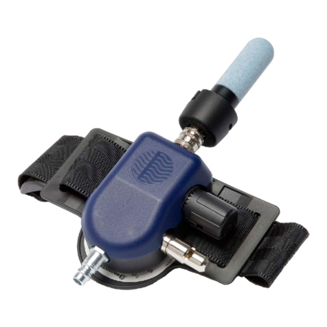
air is connected to a control valve threaded onto the user’s belt.
Thecontrolvalvecanbeusedforadjustingtheairflowratetothe
facepiece.Fromthecontrolvalve,theairflowsthroughabreathing
hose to a connection adapter, and then into the facepiece.
Thecontrolvalveisequippedwithawarningwhistlewhichwillcome
intooperation iftheairflowrateshoulddropbelowtheminimun
designflowrate.
Manufacturer’sminimumdesignflow:120l/min.
1.3 Breathable air
Breathableairshallmeetatleastthefollowingpurityrequirements
according to EN 12021:2014:
• thepollutantsmustbemaintainedataminimumandmustnever
exceed the hygienic limit value
• thecontentofmineraloilshallbesolowthattheairwillhaveno
oil smell (the threshold of smell is around 0.3 mg/m3)
• theairshallhaveasufficientlylowdewpointtoensurethatno
internalfreezingwilltakeplaceintheequipment
Intheeventofuncertaintyastowhethertheabovedemandshave
been met, a filter such as the Sundström type SR 99 compressed
air filter should be connected. Fig. 10. The SR 99 compressed air
filter consists of a pre-collector and a main filter.
The main filter consists of a gas filter section (class A3 as per EN
141:1990andAS/NZS1716:2012)withabout500gofactivated
carbon, surrounded by two particle filters ( class P3 as per EN
143:1990 and AS/NZS 1716:2012). The collecting capacity is 100
- 150 g of oil. For further particulars of breathable air, see European
Standard EN 132:1998, Australian Standard AS/NZS 1715:2009
and any other national regulations that may be in force.
2. Use
2.1 Unpacking
Checkthattheequipmentiscompleteinaccordancewiththepack-
ing list and that no transport damage has occurred.
2.2 Packing list
• Connectionadapterwithhose
• Controlvalve
• Belt
• Lockingring
• Flowmeter
• Userinstructions
2.3 Functional check
On every occasion before using the equipment, check that the
minimumflowofairthroughtheadapterisabout150l/min.
Proceed as follows:
• Connectthebreathinghosetothecontrolvalve.Fig.3.
• Connectthecompressedairhosetothecontrolvalve.Fig.4.
• Turnthecontrolvalveknobanti-clockwiseasfarasitwillgoin
ordertothrottletheairflowratetoaminimum.Fig.3.
• Placetheequipmentinthebag,andgripthelowerpartofthe
bag so that the bag seals around the breathing hose. Grip the
flowmeterwiththeotherhandandholditsothatthetubepoints
vertically up from the bag. Fig. 2.
• Readthepositionoftheballinthetube.Itshouldfloatlevelwith
or just above the marking on the tube.
Iftheflowrateisbelowtheminimumvalue,checkthat
• theflowmeterisvertical
• theballcanmovefreely
• theairsupplyisnotrestrictedbykinksorotherrestrictionsinthe
hoses
2.4 Putting the equipment on
Fig 5-6
• Putthebeltonandadjustthelength.
• Arrangethecontrolvalveinawaythatallowseasyadjustment
oftheflowrateandastrictwatchoverthebreathinghose,i.e.
itmustnotbeplacedonthebackofthewaist.
• Thenadjusttheharnesssothatthefacepieceisheldfirmlybut
comfortably in place. See the user instructions for the facepiece
you are using.
• Thenfit theconnection adapterofthecompressedair attach-
menttothefacepiece.Incombinationwithafullfacemask,the
lockingringshouldalwaysbeusedforsecuringthemountingof
the connection adapter. Fig. 1:6
• Connectthebreathinghoseofthecompressedairattachment
to the control valve outlet. Fig. 3
• Unrollthecompressedairtubeandmakesurethatitisnottwisted.
• Connectthetubetothecontrolvalveinlet.Fig4.
• Thefacepieceisnowbeingsuppliedwithairandyoucanputiton.
• Usethe controlvalveknobtoset theair flowrate tosuityour
currentworkintensity.Fig.3
Inthefullyclosedposition(turntheknobanti-clockwise),theflow
willbetheminimum,andinthefullyopenposition(turntheknob
clockwise),theflowwillbethemaximum.
• Thebreathinghoseretainingclipwhichissuppliedcanbeusedto
advantage for securing the breathing hose to your body. Fig. 1:11


