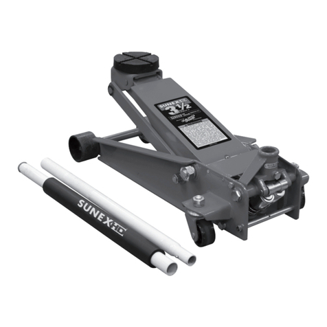
Sunex HD 66037JPK User manual

66037JPK Rev. 1/15/20
CONTENTS:
Page 1 Specifications
2 Warning Information (Service Jack)
3 Warning Information (Jack Stands)
4 Setup Instructions and Operating Instructions
5 Preventative Maintenance, Inspection, Proper Storage, Troubleshooting, and Owner/User Responsibility
6 Hydraulic Jack Maintenance Guide and Regular Maintenance
7 Warranty Information
8 Exploded View Drawing and Replacement Parts (Service Jack and Stands)
9 Exploded View Drawing and Replacement Parts (Power Unit)
OWNER'S MANUAL
66037 Rev. A
Capacity................................................................ 3.5 Ton
Low Height.....................................................................4"
High Height...............................................................19.5"
Overall Length ..........................................................30.6"
Overall Width ............................................................14.3"
Handle Length .............................................................50"
Net Weight........................................................... 100 lbs.
Saddle Diameter.......................................................4.75"
1006 Rev. B
Capacity................................................................... 6 Ton
Low Height..............................................................15.75"
High Height..................................................................24"
Overall Length .........................................10.375" x 11.5"
Net Weight............................................................. 31 lbs.
SERVICE JACK SPECIFICATIONS JACK STAND SPECIFICATIONS
© Copyright 2020, Sunex Tools®
66037JPK
CAPACITY: 3.5 TON
SERVICE JACK WITH
6 TON JACK STANDS (PAIR)
66037 Rev. A 1006 Rev. B

66037JPK 2 Rev. 1/15/20
This is the safety alert symbol. It is used to alert you to
potential personal injury hazards. Obey all safety messages
that follow this symbol to avoid possible injury or death.
IMPORTANT: READ THESE INSTRUCTIONS BEFORE OPERATING
BEFORE USING THIS DEVICE, READ THIS MANUAL COMPLETELY AND THOROUGHLY, UNDERSTAND ITS OPERATING PROCEDURES,
SAFETY WARNINGS AND MAINTENANCE REQUIREMENTS.
It is the responsibility of the owner to make sure all personnel read this manual prior to using the device. It is also the responsibility of the
device owner to keep this manual intact and in a convenient location for all to see and read. If the manual or product labels are lost or not
legible, contact Sunex for replacements. If the operator is not fluent in English, the product and safety instructions shall be read to and
discussed with the operator in the operator's native language by the purchaser/owner or his designee, making sure that the operator
comprehends its contents.
THE NATURE OF HAZARDOUS SITUATIONS
The use of portable automotive lifting devices is subject to certain hazards that cannot be prevented by mechanical means, but only by the
exercise of intelligence, care, and common sense. It is therefore essential to have owners and personnel involved in the use and operation
of the equipment who are careful, competent, trained, and qualified in the safe operation of the equipment and its proper use. Examples of
hazards are dropping, tipping or slipping of loads caused primarily by improperly securing loads, overloading, off-centered loads, use on
other than hard level surfaces, and using equipment for a purpose for which it was not designed.
METHODS TO AVOID HAZARDOUS SITUATIONS
• Read, study, understand and follow all instructions before operating this device.
• Inspect the jack before each use. Do not use jack if damaged, altered, modified, in poor condition, leaking hydraulic fluid, or
unstable due to loose or missing components. Make corrections before using.
• Lift only on areas of the vehicle as specified by the vehicle manufacturer.
• Wear eye protection that meets ANSI Z87.1 and OSHA standards (users and bystanders).
• Do not use jack beyond its rated capacity. Do not shock Load.
• This is a lifting device only. Immediately after lifting, support the vehicle with jack stands capable of sustaining
the load before working on the vehicle.
• Use only on a hard level surface free from obstructions so the jack is free to reposition itself during lifting and lowering operations.
• Center load on saddle. Be sure setup is stable before working on vehicle.
• Do not move or dolly the vehicle while on the jack.
• Do not use any materials that may serve as risers, spacers or extenders between the stock lifting saddle and the load.
• Do not use any adapters that replace the stock lifting saddle unless approved or supplied by the jack manufacturer.
• Do not use (or modify) this product for any other purpose than that for which it was designed without consulting the
manufacturer's authorized representative.
• Always lower the jack slowly and carefully.
• Failure to heed these warnings may result in serious or fatal personal injury and/or property damage.
WARNING: This product can expose you to chemicals including nickel which is known to the State of California to cause cancer and birth
defects or other reproductive harm. For more information go to www.P65Warnings.ca.gov.
CONSEQUENCES OF NOT AVOIDING HAZARDOUS SITUATIONS
Failure to read this manual completely and thoroughly, failure to understand its OPERATING INSTRUCTIONS, SAFETY WARNINGS,
MAINTENANCE INSTRUCTIONS and comply with them, and failure to comply with the METHODS TO AVOID HAZARDOUS SITUATIONS
could cause accidents resulting in serious or fatal personal injury and/or property damage.
WARNING: Indicates a hazardous
situation which, if not avoided, could
result in death or serious injury.
WARNING INFORMATION - FLOOR SERVICE JACK

66037JPK 3 Rev. 1/15/20
This is the safety alert symbol. It is used to alert you to
potential personal injury hazards. Obey all safety messages
that follow this symbol to avoid possible injury or death.
IMPORTANT: READ THESE INSTRUCTIONS BEFORE OPERATING
BEFORE USING THIS DEVICE, READ THIS MANUAL COMPLETELY AND THOROUGHLY, UNDERSTAND ITS OPERATING PROCEDURES,
SAFETY WARNINGS AND MAINTENANCE REQUIREMENTS.
It is the responsibility of the owner to make sure all personnel read this manual prior to using the device. It is also the responsibility of the
device owner to keep this manual intact and in a convenient location for all to see and read. If the manual or product labels are lost or not
legible, contact Sunex for replacements. If the operator is not fluent in English, the product and safety instructions shall be read to and
discussed with the operator in the operator's native language by the purchaser/owner or his designee, making sure that the operator
comprehends its contents.
THE NATURE OF HAZARDOUS SITUATIONS
The use of portable automotive lifting devices is subject to certain hazards that cannot be prevented by mechanical means, but only by the
exercise of intelligence, care, and common sense. It is therefore essential to have owners and personnel involved in the use and operation
of the equipment who are careful, competent, trained, and qualified in the safe operation of the equipment and its proper use. Examples of
hazards are dropping, tipping or slipping of loads caused primarily by improperly securing loads, overloading, off-centered loads, use on
other than hard level surfaces, and using equipment for a purpose for which it was not designed.
METHODS TO AVOID HAZARDOUS SITUATIONS
• Read, study, understand and follow all instructions before operating this device.
• Inspect the jack stands before each use. Do not use jack stands if damaged, altered, modified, in poor condition, or unstable due to
loose or missing components. Make corrections before using.
• Wear eye protection that meets ANSI Z87.1 and OSHA standards (users and bystanders).
• Do not use jack stands beyond the pair's rated capacity. Do not shock Load.
• Do not crawl under the vehicle while lifting vehicle or placing or removing the jack stands.
• Use as a matched pair only.
• Maximum load capacity per matched pair shall not exceed the rated capacity of the individual stand.
• Use only on a hard level surface capable of supporting the load.
• Stands are to be used in matched pairs to support one end of a vehicle only. Do not simultaneously support both ends
or one side of a vehicle.
• Apply the emergency brake and put the gear shift lever in park or in gear if a manual shift transmission, and chock the tires that will not
be lifted off the ground.
• Ensure both stands are set at same height and locking pawls are fully engaging the support column's teeth.
• Consult the vehicle manufacturer for the proper frame support locations.
• Center load on saddle. Do not use saddle lugs to support the load.
• Check the stands for solid contact with the ground and vehicle. Make sure the stands' locking pawls are fully engaging the support
columns' teeth.
• Do not use (or modify) this product for any other purpose than that for which it was designed without consulting the
manufacturer's authorized representative.
• Failure to heed these warnings may result in serious or fatal personal injury and/or property damage.
WARNING: This product can expose you to chemicals including nickel which is known to the State of California to cause cancer and birth
defects or other reproductive harm. For more information go to www.P65Warnings.ca.gov.
CONSEQUENCES OF NOT AVOIDING HAZARDOUS SITUATIONS
Failure to read this manual completely and thoroughly, failure to understand its OPERATING INSTRUCTIONS, SAFETY WARNINGS,
MAINTENANCE INSTRUCTIONS and comply with them, and failure to comply with the METHODS TO AVOID HAZARDOUS SITUATIONS
could cause accidents resulting in serious or fatal personal injury and/or property damage.
WARNING: Indicates a hazardous
situation which, if not avoided, could
result in death or serious injury.
WARNING INFORMATION - JACK STANDS

66037JPK 4 Rev. 1/15/20
JACK STAND ASSEMBLY INSTRUCTIONS
1. Install the support column in the stand where the support column teeth are facing toward the stand's locking pawl.
2. Raise the stand's locking handle to allow the column to go to its lowest position.
3. In order to prevent removal of the support column from the stand, use a hammer and flat end punch to hammer the jack's tab in
toward the column but not touching the column. Some stands are equipped with a bolt instead of a tab. In this case the bolt can
be threaded in toward the column until the bolt bottoms out.
JACK SETUP
PLEASE REFER TO THE EXPLODED VIEW DRAWING IN THIS MANUAL IN ORDER TO IDENTIFY PARTS.
1. Depress the spring button at the bottom of the upper handle half (#13) and insert it in the lower handle half (#15) until the spring button
engages the hole in the lower handle half.
2. Remove the handle set screw (#17) from the handle yoke (#18). Install the assembled handle into the handle yoke (#18) making sure
the bottom of the handle engages the release valve u-joint (#19).
3. Install the handle set screw (#17) in the handle yoke (#18) and tighten the screw to secure the handle in the yoke.
4. Air may become trapped in the hydraulic system during shipping and handling. Trapped air will affect the pumping performance of the
jack. If this occurs, follow the air purging procedure below:
a) Remove the four screws that secure the cover plate (#22) to the jack frame (#4) so the oil fill screw (#21 - page 9) can be removed
from the hydraulic power unit reservoir tube (#38 - page 9).
b) With the lift arm (#27) in its down position, look inside the oil fill screw hole. You should be able to see the top of the power unit's
cylinder (#29 - page 9). The hydraulic fluid level should be no higher than the top of the cylinder. Correct the fluid level if it
is not at the proper height.
c) Pump the jack against a load that is at least 500 lbs. (225 Kgs). After the load is raised, slightly turn the pump handle in a
counterclockwise rotation so the load is very slowly lowered. While the lift arm is lowering, quickly pump the handle 5 or 6 full
incremental pump strokes. After pumping, lower the lift arm to its full rest position.
d) Install the oil fill screw (#21 - page 9). Rotate the handle in a clockwise rotation until tight and pump the lift arm to maximum height.
Repeat steps "a" through "d" until all of the air has been purged from the system.
e) Install the cover plate (#22) with the four screws.
OPERATING INSTRUCTIONS
This is the safety alert symbol used for the OPERATING INSTRUCTIONS section of this manual to alert you to potential personal
injury hazards. Obey all instructions to avoid possible injury or death.
IMPORTANT: Before attempting to raise any vehicle, check vehicle service manual for recommended lifting surfaces.
JACK STAND OPERATION:
1. Make sure the work floor is clean and free of debris and obstacles.
2. Chock the vehicle's tires that will not be lifted. Make sure the emergency brake is on and the vehicle's transmission is either in the
park mode or gear if a manual transmission.
3. Raise the vehicle to a safe working height and make sure the jack and vehicle setup are stable before positioning the jack stands. DO
NOT CRAWL UNDER THE VEHICLE TO POSITION OR REMOVE STANDS.
4. Position the jack stands right below the areas of the vehicle support points as specified by the vehicle manufacturer.
5. Lift the support columns as close to the vehicle as possible without the saddles on the columns coming in contact with the vehicle. Make
sure the support columns' teeth are engaged with the locking pawls.
JACK OPERATION:
1. To raise load: Turn the handle in a clockwise direction until tight. Position the jack under the load. Proceed to pump the handle in order
to raise the lift arm to the load. As the saddle at the end of the lift arm gets closer to the load, reposition the jack so the saddle will
contact the load firmly and the load is centered on the saddle. Make sure the saddle is correctly positioned. Raise the load to the desired
work height. Place jack stands of appropriate capacity at the vehicle manufacturers's recommended support areas that provide stable
support for the raised vehicle. DO NOT CRAWL UNDER VEHICLE WHILE LIFTING VEHICLE OR PLACING OR REMOVING THE JACK
STANDS! Once jack stands are positioned and stand columns raised to the proper height, turn the jack handle VERY SLOWLY. Lower the
load to rest on the jack stands. Inspect the relationship between the jack stands and load to make sure the setup is stable and safe. If the
setup is not stable or safe, follow the preceding steps until corrected.
2. To lower load: Follow the procedures mentioned in "To raise load" section of the OPERATING INSTRUCTIONS in order to raise the load
off the jack stands. Once the load has cleared the jack stands, remove the stands from under the load and away from the work area. Turn
handle very slowly in a counterclockwise direction until the load is completely lowered to the ground. Once the jack's lifting saddle has
cleared the load, remove the jack from under the load. CAUTION: Keep hands and feet away from the hinge mechanism of the jack. DO
NOT CRAWL UNDER VEHICLE WHILE LIFTING VEHICLE OR PLACING OR REMOVING THE JACK STANDS!
OWNER'S MANUAL
66037JPK
CAPACITY: 3.5 TON
SERVICE JACK WITH
6 TON JACK STANDS (PAIR)

66037JPK 5 Rev. 1/15/20
PREVENTATIVE MAINTENANCE
This is the safety alert symbol used for the PREVENTATIVE MAINTENANCE section of this manual to alert you to potential personal
injury hazards. Obey all instructions to avoid possible injury or death.
1. Always store the jack and jack stands in a well protected area where they will not be exposed to inclement weather, corrosive vapors,
abrasive dust, or any other harmful elements. The jack and jack stands must be cleaned of water, snow, sand, grit, oil, grease or other
foreign matter before using.
2. The jack must be lubricated periodically in order to prevent premature wearing of parts. A general purpose grease must be applied to all
zerk grease fittings, caster wheels, front axle, lift arm, handle base pivot bolts, release mechanism and all other bearing surfaces. Worn
parts resulting from inadequate or no lubrication are not eligible for warranty consideration. See page 6 for lubrication instructions.
3. It should not be necessary to refill or top off the reservoir with hydraulic fluid unless there is an external leak. An external leak requires
immediate repair which must be performed in a dirt-free environment by an authorized service center.
IMPORTANT: In order to prevent seal damage and jack failure, never use alcohol, hydraulic brake fluid or transmission oil in the jack.
Use Chevron Hydraulic Oil AW ISO 32 or its equivalent Unocal Unax AW 150.
4. Every jack and jack stand owner is responsible for keeping the jack labels clean and readable. Use a mild soap solution to wash external
surfaces of the jack but not any moving hydraulic components.
5. Inspect the jack and jack stands before each use. Do not use the jack and jack stands if any component is cracked, broken, bent, shows
sign of damage or leaks hydraulic fluid. Do not use the jack if it has loose or missing hardware or components, or is modified in any way.
Take corrective action before using the jack again.
6. Any hydraulic repairs within the warranty period must be performed by an authorized service center.
INSPECTION
Visual inspection should be made before each use of the jack and stands, checking for leaking hydraulic fluid and damaged, loose or
missing parts. Jack and stands must be inspected by a manufacturer’s repair facility immediately if subjected to an abnormal load or shock.
Any jack or stands which appear to be damaged in any way, are found to be badly worn, or operate abnormally MUST BE REMOVED FROM
SERVICE until necessary repairs are made by a manufacturer’s authorized repair facility. It is recommended that an annual inspection of the
jack and stands be made by a manufacturer’s authorized repair facility and that any defective parts, decals or warning labels be replaced
with manufacturer’s specified parts. A list of authorized repair facilities is available from the manufacturer.
PROPER STORAGE
It is recommended that the jack and jack stands be stored in a dry location with all wheels and stand legs touching the ground on a relatively
levelsurface.
TROUBLESHOOTING
Important: Service jacks are self-contained devices used for lifting, but not sustaining, a partial vehicular load. In accordance with
ASME PASE-2019 Load Sustaining Test: “A load not less than the rated capacity…shall not lower more than 1/8" (3.18mm) in the first minute,
nor a total of .1875" (4.76mm) in 10 minutes.” Lowering within this range is considered normal operation and is NOT a warrantable defect.
OWNER/USER RESPONSIBILITY
The owner and/or user must have an understanding of the manufacturer’s operating instructions and warnings before using this jack.
Personnel involved in the use and operation of equipment shall be careful, competent, trained, and qualified in the safe operation of the
equipment and its proper use when servicing motor vehicles and their components. Warning information should be emphasized and
understood. If the operator is not fluent in English, the manufacturer’s instructions and warning shall be read to and discussed with the
operator in the operator’s native language by the purchaser/owner, making sure that the operator comprehends its contents. Owner and/or
user must study and maintain for future reference the manufacturers’ instructions. Owner and/or user is responsible for keeping all warning
labels and instruction manuals legible and intact. Replacement labels and literature are available from the manufacturer.
OWNER'S MANUAL
PROBLEM ACTION
1. Unit will not lift rated load. Purge air from hydraulic system by following procedure under
SETUP.
2. Unit will not sustain rated load or feels “spongy” under rated load. Purge air from hydraulic system as above.
3. Unit will not lift to full height. Purge air from hydraulic system as above.
4. Handle tends to raise up while the unit is under rated load. Pump the handle rapidly several times to push oil past ball valves in
power unit.
5. Unit still does not operate. Contact Sunex authorized hydraulic service center.
66037JPK
CAPACITY: 3.5 TON
SERVICE JACK WITH
6 TON JACK STANDS (PAIR)

66037JPK 6 Rev. 1/15/20
HYDRAULIC JACK MAINTENANCE GUIDE
IMPORTANT: Service jacks are designed for lifting purposes only; always support raised load with jack stands.
REGULAR MAINTENANCE
• MONTHLY or as necessary (depending on usage)
1. Using a grease gun, add grease to grease fitting in the lift arm pivot shaft.
(Use a multi-purpose NLGI type grease only.)
2. Lubricate all linkages and pivot points.
(Use white lithium spray grease only.)
3. Remove handle; lubricate handle receptacle and handle end.
(Use white lithium spray grease only.)
4. Lubricate both rear casters, bearing and both front wheels.
(Use white lithium spray grease only.)
5. Tighten all accessible hardware.
LIMITED WARRANTY
#3
#4
#4
#1 #2
#2
#3
#2
#2#2 #2
#4
#2
66037JPK
CAPACITY: 3.5 TON
SERVICE JACK WITH
6 TON JACK STANDS (PAIR)

66037JPK 7 Rev. 1/15/20
SUNExpress™ Warranty
This jack is under the SUNEXpress™ Warranty. The SUNEXpress™ Warranty allows Sunex®users to exchange inoperable, defective
service jacks still under 1 year warranty directly with Sunex Tools®. Please call (855) 600 – SWAP or visit www.sunextools.com/sunexpress
for more details.
SUNEX INTERNATIONAL, INC. WARRANTS TO ITS CUSTOMERS THAT THE COMPANY’S SUNEX TOOLS®BRANDED PRODUCTS
ARE FREE FROM DEFECTS IN WORKMANSHIP AND MATERIALS.
Sunex International, Inc. will repair or replace its Sunex Tools®branded products which fail to give satisfactory service due to defective
workmanship or materials, based upon the terms and conditions of the following described warranty plans attributed to that specific
product. This product carries a ONE-YEAR warranty. During this warranty period, Sunex Tools will repair or replace at our option any part
or unit which proves to be defective in material or workmanship.
Other important warranty information
This warranty does not cover damage to equipment or tools arising from alteration, abuse, misuse, damage and does not cover any repairs
or replacement made by anyone other than Sunex Tools®or its authorized warranty service centers. The foregoing obligation is Sunex Tools’
sole liability under this or any implied warranty and under no circumstances shall we be liable for any incidental or consequential damages.
NOTE: Some states do not allow the exclusion or limitation of incidental or consequential damages, so the above limitation or exclusion may
not apply to you. Return equipment or parts to an authorized service center, transportation prepaid. Be certain to include your name and
address, evidence of the purchase date, and description of the suspected defect. If you have any questions about warranty service, please
write to Sunex Tools®. This warranty gives you specific legal rights and you may also have other rights which vary from state to state.
Repair kits and replacement parts are available for many of Sunex Tools products regardless of whether or not the product is still covered by
a warranty plan.
SHIPPING ADDRESS:Sunex Tools • 315 Hawkins Rd. • Travelers Rest, SC 29690
MAILING ADDRESS: Sunex Tools • P.O. Box 1233 • Travelers Rest, SC 29690
LIMITED WARRANTY
66037JPK
CAPACITY: 3.5 TON
SERVICE JACK WITH
6 TON JACK STANDS (PAIR)

66037JPK 8 Rev. 1/15/20
PARTS LIST AND DRAWING
Replacement parts not available due to safety
precautions except for product label kit:
RS1006LK - 1 pair of labels.
Post
Base
Tab
66037JPK
CAPACITY: 3.5 TON
SERVICE JACK WITH
6 TON JACK STANDS (PAIR)
1
2
3
4
5
6
7
8
9
10
11
12
14
13
15
16
17
18
20
21
22
23
28
29
30
24
25
26
27
31
32
19
Only items identified by part number are available for purchase.
REF # PART# DESCRIPTION QTY
1 RS35T01 Star Clip (20) 2
2 RS35T02 Washer (M20) 2
3 RS35B03 Front Wheel (Black) 2
4 Side Plate Assembly 1
5 RS35B10 Rear Caster Assembly (Black) (incl. #8, 10) 2
6 Bolt (M12x22) 4
7 Washer (12) 4
8 Washer (16) (incl. with #5) 2
9 Bolt (M5x12) 4
10 Nut (M16) (incl. with #5) 2
11 Washer (18) (incl. with #12) 2
12 RS35B11 Yoke Retaining Bolt (incl. #11) 2
13 RS35T17BK Upper Handle (Black) 1
14 Handle Button 1
15 RS35T15BK Lower Handle (Black) 1
16 RS35T20S Handle Bumper 1
17 RS35T13 Handle Set Screw (incl. #18) 1
REF # PART# DESCRIPTION QTY
18 RS35B16 Handle Yoke (Red) (incl. #17) 1
19 RS35T18 U-Joint Assembly 1
20 RS35B20 Power Unit Assembly (Black) 1
21 RS35T19 Return Spring 2
22 Cover Plate 1
23 Retaining Ring (25) 2
24 Pin (A4x55) 1
25 RS35B24 Linkage Rod (Black) (w/ #23 & 24) 2
26 RS35T12 Grease Fitting 1
27 Lift Arm 1
28 Link Rod Linkage Bolt 2
29 Link Rod Assembly 2
30 Cotter Ring (15) 2
31 RS35B30BK Saddle (Black) 1
32 RS35B31NL Rubber Saddle 1
RS66037APLK Product Label Kit (not shown) 1

66037JPK 9 Rev. 1/15/20
44
28
34
30
32
33
31
29
25
26
23
24
21
22 40 11
27
35
21
36
37
10
13
12
14 11 1
41
38
39
7
20
16
17
18
19
15
43
2
42
3
5
6
8
9
Power Unit Assembly
RS35B20
* Included in Seal Kit - RS35BSK
Only items identified by part number are available for purchase.
PARTS LIST AND DRAWING
REF # PART# DESCRIPTION QTY
1 * Steel Ball (7.5) 1
2 Large Pump Housing 1
3 * O-Ring (20.4x2.65) 2
5 Big Pump Piston 1
6 Pump Spring 1
7 RSDC22 Dust Cover 1
8 Washer 1
9 RSRR27 Retaining Ring (25) 1
10 RS35T18 Universal Joint Assembly 1
11 * Steel Ball (6) 2
12 * Brass Washer 1
13 Small Pump Housing 1
14 * O-Ring (10x2.65) 2
15 * Back-up Washer (15x10.6x1.25) 2
16 Small Pump Piston 1
17 Pump Spring 1
18 RSDC15 Dust Cover 1
19 Washer 1
20 RSRR16 Retaining Ring (15) 1
21 RSOFS37 Oil Fill Screw (incl. #22) 3
22 * O-Ring (7.1x1.8) (incl. with #21) 3
23 Relief Valve Bolt 1
24 * Relief Valve Spring 1
REF # PART# DESCRIPTION QTY
25 * Plug 1
26 * Steel Ball (4) 1
27 Hydraulic Block 1
28 * Cylinder Seal 1
29 Cylinder 1
30 * O-Ring (31x4.6) 1
31 * Gasket 1
32 Ram Bearing 1
33 Retaining Ring (30) 1
34 Ram 1
35 Cylinder Nut 1
36 * O-Ring (29.6x3.5) 1
37 * Gasket 1
38 Reservoir Tube 1
39 * Gasket 1
40 * Steel Ball (5) 4
41 * Separator Spring 1
42 * Steel Ball (8) 1
43 * Spacer 1
44 * Brass Washer 1
66037JPK
CAPACITY: 3.5 TON
SERVICE JACK WITH
6 TON JACK STANDS (PAIR)

66037JPK 10 Rev. 1/15/20
66037 Rev. A
Capacidad ................................................... 3.5 Tonelada
Altura mínima.................................................................4"
Altura máxima...........................................................19.5"
Longitud global.........................................................30.6"
Anchura global .........................................................14.3"
Longitud del mango ....................................................50"
Peso neto ......................................................... 100 libras
Diámetro del asiento................................................4.75"
1006 Rev. B
Capacidad ...................................................... 6 Tonelada
Altura mínima..........................................................15.75"
Altura máxima..............................................................24"
Tamaño bajo ............................................10.375" x 11.5"
Peso neto ........................................................... 31 libras
GATO DE SERVICIO ESPECIFICACIONES BASES DE GATO ESPECIFICACIONES
MANUAL DEL PROPIETARIO
CONTENIDO:
Página 10 Especificaciones
11 Información de advertencia (gato de servicio para piso)
12 Información de advertencia (bases de gato)
13 Instrucciones de ensamble y uso
14 Mantenimiento preventivo, inspeccione, y almacenamiento adecuado
15 Diagnóstico de averías, responsabilidad del propietario/usuario y información de garantía
16 Guía de mantenimiento del gato hydáulico y mantenimiento regular
8 Dibujo de vista ampliada y partes de repuesto (gato de servicio y bases de gato)
9 Dibujo de vista ampliada y partes de repuesto (el aparato de capacidad eléctrica)
© Copyright 2020, Sunex Tools®
66037JPK
CAPACIDAD: 3.5 TONELADA
GATO DE SERVICIO CON BASES DE
GATO DE 6 TONELADAS (PARES)
66037 Rev. A 1006 Rev. B

66037JPK 11 Rev. 1/15/20
INFORMACIÓN DE ADVERTENCIA - GATO DE SERVICIO
Este símbolo indica una alerta de seguridad y se usa
para advertir sobre peligro de accidentes personales.
Observe toda la información de seguridad que sigue a
este símbolo para evitar la posibilidad de que ocurran
lesiones o muerte.
IMPORTANTE: LEA ESTAS INSTRUCCIONES ANTES DE USAR EL DISPOSITIVO
ANTES DE USAR ESTE DISPOSITIVO, LEA ESTE MANUAL DETENIDAMENTE. PROCURE ENTENDER SUS PROCEDIMIENTOS OPERATIVOS,
ADVERTENCIAS DE SEGURIDAD Y REQUERIMIENTOS DE MANTENIMIENTO.
El propietario es responsable de asegurarse de que todo el personal lea este manual antes de usar el dispositivo. Asimismo, es
responsabilidad del propietario mantener este manual en buenas condiciones en una ubicación conveniente para su consulta. Si las
etiquetas del manual o producto están extraviadas o son ilegibles, comuníquese con SUNEX por sus repuestos. El comprador/propietario o
una persona designada deberá leer y comentar el producto y las advertencias de seguridad en la lengua materna del operario, si es que no
domine el inglés, a fin de asegurarse de que comprende el contenido.
NATURALEZA DE LAS SITUACIONES DE RIESGO
El uso de dispositivos de elevación portátiles se halla sujeto a ciertos riesgos que no se pueden prever por medios mecánicos, sino por
la inteligencia, el cuidado y el sentido común. Por lo tanto, es esencial que el uso del dispositivo quede en manos de los propietarios y de
personal que sea cuidadoso, competente, capacitado y habilitado para realizar un uso adecuado y operación segura del equipo. Algunos
ejemplos de peligros son dejar caer, inclinar o resbalar las cargas, principalmente como consecuencia de un sujeción de carga incorrecta,
sobrecarga, posición no centrada, uso en superficies no niveladas o firmes, así como usar el dispositivo con un fin para el que no está
diseñado.
FORMAS DE EVITAR LAS SITUACIONES DE RIESGO
• Lea, estudie, comprenda y observe todas las instrucciones antes de operar este dispositivo.
• Verifique el gato antes de usarlo. No lo use si tiene roturas, alteraciones, o está en malas condiciones, como tampoco si presenta
inestabilidad debido a piezas metálicas o partes desajustadas o faltantes. Tome las medidas de corrección apropiadas antes de
usarlo.
• Utilice el dispositivo de elevación únicamente en las áreas del vehículo especificadas por su fabricante.
• Use protección para los ojos que cumpla con las normas ANSI Z87.1 y OSHA (usuarios y espectadores).
• No use el gato para elevar pesos superiores a su capacidad. No ocasione ninguna descarga a la carga.
• Este dispositivo se debe utilizar únicamente para levantar cargas. No bien haya elevado la carga, sujete el vehículo
con torres que tengan la capacidad para sostenerlo antes de comenzar a trabajar.
• Use el gato únicamente en superficies niveladas firmes en las que no haya obstáculos, de modo que el dispositivo pueda
posicionarse durante las operaciones de elevación y descenso.
• Centre la carga en el asiento. Asegúrese de que el armado del dispositivo sea estable antes de comenzar a trabajar.
• No mueva ni empuje el vehículo sobre el gato.
• No use ningún material que pueda fungir como plataforma, espaciador o expansor entre la silla de elevación estándar y la carga.
• No use ningún adaptador el que reponga la silla de elevación estándar al menos que sea aprobado o provisto por el fabricante
del gato.
• No use (ni altere) este producto para ningún propósito excepto el para el cual fue destinado, sin primero consultar al representante
autorizado del fabricante.
• Baje el gato siempre despacio y con cuidado.
• No cumplir con estas indicaciones puede provocar lesiones graves o peligro de muerte, así como daños materiales.
ADVERTENCIA: Este producto le podrá exponer a ciertos químicos, para incluir el níquel, conocidos en el Estado de California por
ocasionar cáncer y defectos congénitos u otros daños a la reproducción. Para mayores informes, visite: www.P65Warnings.ca.gov.
LAS CONSECUENCIAS DE NO EVITAR SITUACIONES DE RIESGO
No leer, comprender u observar todo el contenido de este manual en relación con sus INSTRUCCIONES DE USO, ADVERTENCIAS DE
SEGURIDAD y FORMA DE MANTENIMIENTO, así como desatender las FORMAS DE EVITAR LAS SITUACIONES DE RIESGO, puede provocar
accidentes que tengan como consecuencia lesiones graves, peligro de muerte o daños materiales.
ADVERTENCIA: Indica una situación
peligrosa que si no se evita, puede
provocar la muerte o lesiones graves.

66037JPK 12 Rev. 1/15/20
INFORMACIÓN DE ADVERTENCIA - BASES DE GATO (PARES)
Este símbolo indica una alerta de seguridad y se usa
para advertir sobre peligro de accidentes personales.
Observe toda la información de seguridad que sigue a
este símbolo para evitar la posibilidad de que ocurran
lesiones o muerte.
IMPORTANTE: LEA ESTAS INSTRUCCIONES ANTES DE USAR EL DISPOSITIVO
ANTES DE USAR ESTE DISPOSITIVO, LEA ESTE MANUAL DETENIDAMENTE. PROCURE ENTENDER SUS PROCEDIMIENTOS OPERATIVOS,
ADVERTENCIAS DE SEGURIDAD Y REQUERIMIENTOS DE MANTENIMIENTO.
El propietario es responsable de asegurarse de que todo el personal lea este manual antes de usar el dispositivo. Asimismo, es
responsabilidad del propietario mantener este manual en buenas condiciones en una ubicación conveniente para su consulta. Si las
etiquetas del manual o producto están extraviadas o son ilegibles, comuníquese con SUNEX por sus repuestos. El comprador/propietario
o una persona designada deberá leer y comentar el producto y las advertencias de seguridad en la lengua materna del operario, si es que
no domine el inglés, a fin de asegurarse de que comprende el contenido.
NATURALEZA DE LAS SITUACIONES DE RIESGO
El uso de dispositivos de elevación portátiles se halla sujeto a ciertos riesgos que no se pueden prever por medios mecánicos, sino por
la inteligencia, el cuidado y el sentido común. Por lo tanto, es esencial que el uso del dispositivo quede en manos de los propietarios y de
personal que sea cuidadoso, competente, capacitado y habilitado para realizar un uso adecuado y operación segura del equipo. Algunos
ejemplos de peligros son dejar caer, inclinar o resbalar las cargas, principalmente como consecuencia de un sujeción de carga incorrecta,
sobrecarga, posición no centrada, uso en superficies no niveladas o firmes, así como usar el dispositivo con un fin para el que no está
diseñado.
FORMAS DE EVITAR LAS SITUACIONES DE RIESGO
• Lea, estudie, comprenda y observe todas las instrucciones antes de operar este dispositivo.
• Previo a cada uso, inspeccione las bases del gato. No las use si están dañadas, modificadas, cambiadas, en pobres condiciones
o si cuentan con ferretería floja o faltante. Tome las medidas de corrección apropiadas antes de usarlo.
• Use protección para los ojos que cumpla con las normas ANSI Z87.1 y OSHA (usuarios y espectadores).
• No use las bases del gato más allá de la capacidad nominal del par de bases. No le dé ningún choque a la carga.
•
No se arrastre debajo del vehículo mientras que se esté levantando el vehículo o al momento de quitar los soportes de gato.
• Use un par emparejado solamente.
• La máxima capacidad de carga por par emparejado no deberá exceder la capacidad nominal de la base individual.
• Úsela solo sobre superficies duras y niveladas, capaces de sostener la carga.
• Las bases deben usarse en pares emparejados para soportar un extremo del vehículo solamente. No soporte ambos extremos
simultáneamente o sólo un lado del vehículo.
• Aplique el freno de emergencia, ponga la palanca de cambio en la posición de estacionado o en alguna otra posición si es una
transmisión de cambio manual y calce las llantas las que no serán levantadas del piso.
• Asegúrese que ambas bases estén ajustadas a la misma altura y que las clavijas estén completamente encajadas.
• Consulte el fabricante del vehículo por las ubicaciones adecuadas de soporte del bastidor.
• Centre la carga en el asiento. No use los extremos de la silla para soportar la carga.
• Revise las bases por un contacto sólido con el piso y con el vehículo. Asegúrese que los linguetes de seguridad de la base estén
completamente encajados con los dientes de la columna de soporte.
• No use (ni altere) este producto para ningún propósito excepto el para el cual fue destinado, sin primero consultar al representante
autorizado del fabricante.
• No cumplir con estas indicaciones puede provocar lesiones graves o peligro de muerte, así como daños materiales.
ADVERTENCIA: Este producto le podrá exponer a ciertos químicos, para incluir el níquel, conocidos en el Estado de California por
ocasionar cáncer y defectos congénitos u otros daños a la reproducción. Para mayores informes, visite: www.P65Warnings.ca.gov.
LAS CONSECUENCIAS DE NO EVITAR SITUACIONES DE RIESGO
No leer, comprender u observar todo el contenido de este manual en relación con sus INSTRUCCIONES DE USO, ADVERTENCIAS DE
SEGURIDAD y FORMA DE MANTENIMIENTO, así como desatender las FORMAS DE EVITAR LAS SITUACIONES DE RIESGO, puede provocar
accidentes que tengan como consecuencia lesiones graves, peligro de muerte o daños materiales.
ADVERTENCIA: Indica una situación
peligrosa que si no se evita, puede
provocar la muerte o lesiones graves.

66037JPK 13 Rev. 1/15/20
INSTRUCCIONES DE ENSAMBLADO DE LA BASES DE GATO
1. Instale la columna de soporrte en la base donde los dientes de la columna de soporte estén orientados hacia el linguete de seguridad
de la base.
2. La mayoría de las bases del gato tipo pasador están diseñados con una columna de soporte que siempre puede ser extraída de la
base, por lo tanto no intente mover ni levantar la base al jalar la columna ni la silla hacia arriba.
3. Algunas bases están equipadas con un portador de almacenamiento para el pasador de seguridad. Los pasadores de seguridad están
conectados a la base por medio de una atadura o cordón y no deben almacenarse en el agujero receptor de la columna de soporte de
la base.
MONTAJE DEL GATO
CONSULTE POR FAVOR EL DIBUJO DE VISTA EN DETALLE EN ESTE MANUAL PARA IDENTIFICAR LAS PARTES.
1. Presione el botón de resorte al fondo de la mitad del mango (#13), e insértela en la mitad inferior del mango (#15) hasta que el botón
de resorte se encaje en el agujero en la mitad inferior del mango.
2. Extraiga el tornillo prisionero de mango (#17), del yugo del mango (#18). Instale el mango ensamblado en el yugo del mango (#18),
asegurándose que el fondo del mango se encaje en la junta en U de la válvula de liberación (#19).
3. Instale el tornillo prisionero del mango (#17), en el yugo del mango (#18) y apriete el tornillo para asegurar el mango en el yugo.
4. Se puede atrapar en el aire en el sistema hidráulico durante en envío y maniobra. El aire atrapado afectará el rendimiento del bombeo
del gato. Si esto se ocurre, siga el procedimiento de purga de aire a continuación:
a) Extraiga los cuatro tornillos los que sujetan la placa cobertora (#22) al armazón de gato (#4) con el fin de que el tornillo de rellenado
de aceite (#21 - página 9) pueda extraerse del tubo reservorio de la unidad de potencia hidráulica (#38 - página 9).
b) Con el brazo de levantamiento (#27) en su posición baja, mire el interior del agujero del tornillo de rellenado de aceite. Usted debe
alcanzar a ver la parte superior del cilindro de la unidad de potencia (#29 - página 9). El nivel de líquido hidráulico no debe estar
más arriba de la parte superior del cilindro. Corrija el nivel de líquido si éste no está a la altura adecuada.
c) Bombee el gato contra una carga no menor de 500 lbs. (225 Kgs). Después de que la carga esté elevada, gire el mango de la
bomba ligeramente en una rotación de contrasentido de las agujas del reloj para que la carga se baje muy lentamente. Mientras
que el brazo de levantamiento esté bajándose, rápidamente bombee el mango de levantamiento 5 ó 6 recorridos incrementales
completos de la bomba. Después de bombear, baje el brazo hasta su posición de reposo integral.
d) Instale el tornillo de rellenado de aceite (#21 - página 9). Gire el mango en una rotación del sentido de las agujas del reloj hasta que
esté apretado y bombee el brazo de levantamiento hasta su altura máxima. Repita los pasos "a" al "d" hasta que se haya purgado
todo el aire del sistema.
e) Instale la placa cobertora (#22) con cuatro tornillos.
INSTRUCCIONES DE USO
Este símbolo indica una alerta de seguridad y se utiliza en la parte de este manual que versa sobre las INSTRUCCIONES DE
USO, con el fin de advertir sobre los peligros de accidentes personales. Observe todas las instrucciones para evitar lesiones o
peligros de muerte. IMPORTANTE: antes de comenzar a elevar un vehículo, consulte su manual de servicio para conocer las
superficies de elevación recomendadas.
OPERACIÓN DE LA BASE DE GATO:
1. Asegúrese que el piso de trabajo esté limpio y libre de escombros y obstáculos.
2. Calce las llantas del vehículo que no serán levantados. Si es una transmisión manual, asegúrese que el freno de emergencia esté
activado y que la transmisión del vehículo esté en park o en otra posición de la palanca de cambios.
3. Eleve el vehículo hasta una altura de trabajo segura y asegúrese que el gato y el ensamblaje del vehículo estén estables antes de colocar
las bases del gato. NO SE META DEBAJO DEL VEHÍCULO PARA COLOCAR NI PARA EXTRAER LAS BASES.
4. Coloque las bases del gato directamente debajo de las áreas de los puntos de soporte del vehículo, según sean especificadas por el
fabricante del vehículo.
5. Levante las columnas de soporte lo más cerca posible al vehículo sin que las sillas en las columnas tengan contacto con el vehículo.
Asegúrese que los dientes de las columnas de soporte estén encajadas con el trinquete de seguridad.
OPERACIÓN DEL GATO DE SERVICIO:
1. Para levantar la carga: Gire el mango en el sentido de las agujas del reloj hasta que esté apretado. Coloque el gato debajo de la
carga. Proceda a bombear el mango para levantar el brazo de levantamiento hasta el nivel de la carga. En le medida que la silla en el
extremo del brazo de levantamiento se acerque a la carga, posicione el gato de nuevo, con el fin de que la silla tenga contacto firme
con la carga y la carga esté centrada sobre la silla. Asegúrese que la silla esté posicionada correctamente. Levante la carga hasta la
altura de trabajo deseada. Coloque los soportes del gato de la capacidad adecuada en los puntos de soporte recomendados por el
fabricante, los que brindan un soporte estable para el vehículo levantado. ¡NO SE ARRASTRE DEBAJO DEL VEHÍCULO MIENTRAS
QUE SE ESTÉ LEVANTANDO EL VEHÍCULO O AL MOMENTO DE QUITAR LOS SOPORTES DEL GATO! Una vez que los soportes
del gato estén posicionados, gire el mango MUY LENTAMENTE. Baje la carga hasta que se recargue sobre los soportes del gato.
Inspeccione la relación entre los soportes de gato y la carga para asegurar que el montaje esté estable y seguro. Si el montaje no esté
seguro ni estable, siga los pasos anteriores hasta que esté corregido.
MANUAL DEL PROPIETARIO
66037JPK
CAPACIDAD: 3.5 TONELADA
GATO DE SERVICIO CON BASES DE
GATO DE 6 TONELADAS (PARES)

66037JPK 14 Rev. 1/15/20
2. Para bajar la carga: Siga los procedimientos mencionados en la sección de "para levantar la carga" de las INSTRUCCIONES DE
OPERACIÓN para levantar la carga fuera de los soportes del gato. Una vez que la carga sea liberada de los soportes del gato, quite los
soportes de debajo de la carga y colóquelos lejos del área de trabajo. Gire el mango muy lentamente en el contrasentido de las agujas
del reloj hasta que la carga esté completamente bajada al piso. Una vez que la silla de levantamiento del gato se haya despejado de la
carga, quite el gato de debajo de la carga. PRECAUCIÓN: Mantenga las manos y los pies lejos del eje de articulación del gato. ¡NO SE
ARRASTRE DEBAJO DEL VEHÍCULO MIENTRAS QUE SE ESTÉ LEVANTANDO EL VEHÍCULO O AL MOMENTO DE QUITAR LOS
SOPORTES DEL GATO!
MANTENIMIENTO PREVENTIVO
Este es el símbolo de alerta de seguridad usado para la sección de MANTENIMIENTO PREVENTIVO de este manual para alertarle
a usted de los peligros de lesión personal potenciales. Obedezca todas las instrucciones con el fin de evitar lesiones potenciales
o aún la muerte.
1. Siempre almacene el gato y las bases del gato en un área bien protegido donde no estarán expuestos a las inclemencias del tiempo, los
vapores corrosivos, polvo abrasivo, o cualquier otro elemento dañino. Antes del uso, el gato y las bases del gato deberán estar limpios
de agua, nieve, arena, arenilla, aceite, grasa o cualquier otro material foráneo.
2. El gato se debe lubricar en forma periódica a fin de prevenir el desgaste prematuro de sus partes. Se debe aplicar grasa de uso general
en todas las articulaciones, las ruedas pivotantes y del eje delantero, el brazo elevador, los pernos pivotantes de la base de la palanca,
el sistema de seguridad y las demás superficies de apoyo. Las partes desgastadas resultando de la lubricación inadecuada o faltante
no serán elegibles para consideraciones de garantía. Ver la página 16 por las instrucciones de lubricación.
3. No debería ser necesario recargar ni llenar el receptáculo del líquido hidráulico, salvo si existen fugas. En caso de fugas, un técnico
calificado en reparación de sistemas hidráulicos que conozca el funcionamiento de este dispositivo deberá realizar su reparación
inmediata en un lugar libre de suciedad.
IMPORTANTE: A fin de prevenir daños en las juntas herméticas y fallas en el dispositivo, no use alcohol, líquido de frenos hidráulicos ni
aceite de transmisión en el gato. Use aceite hidráulico AW ISO 32 de Chevron o su equivalente Unocal Unax AW 150.
4. Cada propietario del gato y base del gato será responsable por mantener limpias y legibles las etiquetas del gato. Use una solución
jabonosa suave para lavar el exterior del gato, sin aplicarla a ninguna de las partes del sistema hidráulico.
5. Antes de cada uso, inspeccione el gato y las bases del gato. No use el gato y las bases del gato si cualquier componente se encentre
agrietado, roto, doblado o si demuestre señas de daños o fugas de líquido hidráulico. No use el gato si presenta alteraciones o es
inestable debido a piezas metálicas o partes desajustadas o faltantes. Tome las medidas de corrección apropiadas antes de usar el gato
otra vez.
6. No repare el sistema hidráulico a menos que sea un técnico calificado que conozca el funcionamiento de este dispositivo.
INSPECCIONE
Se debe realizar una inspección visual previo cada uso del gato, revisando por fugas en el líquido hidráulico y por partes dañadas, flojas
o faltantes. Cada gato debe ser inspeccionado inmediatamente por parte de un centro de reparación del fabricante, si éste esté sujetado
a un choque o a una carga anormal. Cualquier gato que aparenta ser dañado de cualquier forma, que se encuentre ser desgastado o que
opera de forma anormal, DEBE DEJARSE DE USAR hasta que se realicen las reparaciones necesarias por parte de un centro de reparación
autorizado del fabricante. Se recomienda que se haga una inspección anual del gato por parte de un centro de reparación autorizado del
fabricante y que cualquier parte, calcomanía o etiqueta de advertencia defectuosa sea repuesta con partes especificadas del fabricante.
Una lista de los centros de reparación autorizados está disponible con el fabricante.
ALMACENAMIENTO ADECUADO
Se recomienda que el gato y las bases de gato se almacenen en un lugar seco con todas las ruedas y patas de base con contacto al piso
sobre una superficie relativamente nivelada.
DIAGNÓSTICO DE AVERÍAS
Importante: Los gatos de servicio son dispositivos autónomos usados para el levantamiento, pero no para el sostenimiento, de una carga
vehicular parcial. De acuerdo con la norma de ASME PASE-2019, de la prueba de sostenimiento de carga: “Una carga no menos que la ca-
pacidad nominal …no deberá más de 1/8" (3.18mm) en el primer minuto, ni un total de .1875" (4.76mm) en 10 minutos.” Bajar dentro de este
rango se considera como una operación normal y NO es un defecto garantizable.
MANUAL DEL PROPIETARIO
66037JPK
CAPACIDAD: 3.5 TONELADA
GATO DE SERVICIO CON BASES DE
GATO DE 6 TONELADAS (PARES)

66037JPK 15 Rev. 1/15/20
RESPONSABILIDAD DEL PROPIETARIO/USUARIO
El propietario y/o usuario debe contar con una comprensión de las instrucciones y advertencias de operación del fabricante antes de usar
este gato. El personal involucrado en el uso y operación del equipo debe ser cuidadoso, competente, capacitado o calificado en la operación
segura del equipo y su uso adecuado al momento de dar mantenimiento a los vehículos motores y sus componentes. La información de
advertencia debe ser enfatizada y comprendida. Si el operador no domina el idioma inglés, las instrucciones y advertencia del fabricante
le deben ser leidas y discutidas con el operador en su idioma nativo por parte del comprador/propietario, asegurándose que el operador
comprenda su contenido. El propietario y/o usuario debe estudiar y mantener las instrucciones del fabricante para su referencia futura.
El propietario y/o usuario será responsable por mantener legibles e intactos las etiquetas de advertencia y los manuales de instrucción.
Las etiquetas y literatura de repuesto están disponibles con el fabricante.
MANUAL DEL PROPIETARIO
Garantía SUNExpress™
Este gato está cubierto bajo la garantía de SUNEXpress™. La garantía SUNEXpress™ les permite a los usuarios de Sunex®intercambiar
directamente con Sunex Tools®los gatos de servicio inoperables y defectuosos aún cubiertos por una garantía de un año. Comuníquese
por favor al (855) 600 – SWAP o visite www.sunextools.com/sunexpress por más detalles.
SUNEX INTERNATIONAL, INC., LE GARANTIZA A SUS CLIENTES QUE LAS HERRAMIENTAS Y PRODUCTOS CON LA MARCA DE LA
EMPRESA SUNEX TOOLS NO CONTIENEN DEFECTOS EN SU MANO DE OBRA NI MATERIAS PRIMAS.
Sunex International, Inc., reparará o sustituirá sus productos con la marca Sunex Tools® que reflejen fallas en el funcionamiento satisfactorio
debido a que la mano de obra o las materias primas estén defectuosas, tomando como base las cláusulas y condiciones de los planes de
garantía descritos a continuación y asignados a ese producto específico. Esteproducto tiene una garantía de UN AÑO. Durante este periodo
de garantía, Sunex Tools reparará o repondrá, a nuestra opción, cualquier parte o unidad la cual demuestra ser defectuosa en cuanto a
material o mano de obra.
Otra importante información de la garantía
Esta garantía no cubre daños a equipo o herramientas debido a modificaciones, abuso, mal uso o daños y no cubre ninguna reparación
o sustitución hecha por ninguna persona que no sea Sunex Tools® o alguno de sus centros de servicio de garantía autorizados. La
obligación antes mancionada queda bajo la responsabilidad exclusiva de Sunex Tools® según se menciona o de cualquier garantía implícita
y bajo ninguna circunstancia quedará bajo su responsabilidad cualquier garantía implícita ya bajo ninguna circunstancia quedará bajo su
responsabilidad cualquier daño incidental o consecuencial.
NOTA: Algunos estados no permiten la exclusión ni limitación de daños. Devuelva el equipo o partes a un centro de servicio autorizado,
con el flete prepagado. Asegúrese de incluir su nombre y dirección, comprobación de la fecha de compra, y la descripción del defecto
sospechado. Si usted tiene alguna pregunta acerca del servicio de garantía, escriba por favor a Sunex Tools®. Esta garantía le brinda
derechos legales específicos y usted puede contar con derechos adicionales los cuales varían de estado a estado. Están disponibles
equipos de reparación y partes de sustitución para muchos de los productos de Sunex Tools, independientemente del hecho de que el
producto aún esté cubierto o no por un plan de garantía.
GARANTÍA LIMITADA
DIRECCIÓN A EMBARCARSE: Sunex Tools • 315 Hawkins Rd. • Travelers Rest, SC 29690
DIRECCIÓN DE CORREOS: Sunex Tools • P.O. Box 1233 • Travelers Rest, SC 29690
PROBLEMA ACCIÓN
1. El equipo no levantará la carga nominal. Expulsa el aire del sistema hidráulico al seguir el procedimiento
bajo INSTRUCCIONES DE ENSAMBLE.
2. El equipo no sostendrá la carga o se siente "esponjoso" bajo
una carga clasificada. Expulsa el aire del sistema hidráulico como indicado anteriormente.
esponjoso bajo la carga.
3. El equipo no levantará la carga hasta la altura normal. Expulsa el aire del sistema hidráulico como indicado anteriormente.
4. El mango tiende a elevarse mientras que el equipo esté debajo
de la carga nominal. Sube y baja el mango rápidamente varias veces para empujar
sostiene una carga el aceite más allá de las válvulas de cojinete en
el aparato de capacidad eléctrica.
5. El equipo aún no funciona. Comuníquese con un centro de servicio hidráulico autorizado de
Sunex.
66037JPK
CAPACIDAD: 3.5 TONELADA
GATO DE SERVICIO CON BASES DE
GATO DE 6 TONELADAS (PARES)

66037JPK 16 Rev. 1/15/20
GUÍA DE MANTENIMIENTO DEL GATO HIDRÁULICO
IMPORTANTE: Los gatos de servicio están diseñados para propósitos de levantamiento solamente; siempre sostenga la carga
elevada con la base de gato.
MANTENIMIENTO REGULAR
• Mensualmente o según sea necesario (dependiendo del uso)
1. Usando una pistola engrasadora, agrega grasa a la grasera en el eje de pivote del brazo de levantamiento.
(Use una grasa multi-uso tipo NLGI solamente.)
2. Lubrique todas las vinculaciones y puntos de pivote.
(Use grasa blanca de litio para atomización solamente.)
3. Quite el mango; lubrique el recipiente del mango y la punta del mango.
(Use grasa blanca de litio para atomización solamente.)
4. Lubrique ambas rodajas posteriores, cojinetes, y ambas ruedas delanteras.
(Use grasa blanca de litio para atomización solamente.)
5. Apriete toda la ferretería accesible.
#3
#4
#4
#1 #2
#2
#3
#2
#2#2 #2
#4
#2
MANUAL DEL PROPIETARIO
66037JPK
CAPACIDAD: 3.5 TONELADA
GATO DE SERVICIO CON BASES DE
GATO DE 6 TONELADAS (PARES)

66037JPK 17 Rev. 1/15/20
CONTENU :
Page 17 Spécifications
18 Information d'avertissement (cric de service)
19 Information d'avertissement (chandelles)
20 Installation et mode d'emploi
21 Entretien préventif, vérification et entreposage adéquat
22 Dépannage, responsabilité du propriétaire/utilisateur et information de garantie
23 Guide d'entretien de cric hydraulique et entrtretien régulier
8 Dessin de vue éclatée et pièces de rechange (cric de service et chandelles)
9 Dessin de vue éclatée et pièces de rechange (unité de puissance)
66037 Rev. A
Capacité............................................................3,5 Tonne
Hauteur minimum..................................................... 4 po
Hauteur maximum............................................... 19,5 po
Longueur totale ................................................... 30,6 po
Largeur totale ...................................................... 14,3 po
Longueur de la poignée......................................... 50 po
Poids net........................................................... 100 livres
Diamètre de la selle............................................. 4.75 po
1006 Rev. B
Capacité...............................................................6 Tonne
Hauteur minimum.............................................. 15,75 po
Hauteur maximum.................................................. 24 po
Taille basse ......................................10,375 po x 11,5 po
Poids net............................................................. 31 livres
CRIC DE SERVICE SPÉCIFICATIONS CHANDELLES SPÉCIFICATIONS
MANUEL DU PROPRIÉTAIRE
© Copyright 2020, Sunex Tools®
66037JPK
CAPACITÉ: 3,5 TONNE
CRIC D’ATELIER AVEC DES
CHANDELLES D’ATELIER 6 TONNES
66037 Rev. A 1006 Rev. B

66037JPK 18 Rev. 1/15/20
Ce symbole indique un danger potentiel. Il est utilisé
pour avertir l'utilisateur des risques potentiels de
blessures corporelles. Prière de respecter toutes les
consignes de sécurité qui suivent ce symbole afin
d'éviter les blessures ou la mort potentielles.
IMPORTANT : LIRE CES CONSIGNES AVANT L'UTILISATION
PRIÈRE DE LIRE CES CONSIGNES ATTENTIVEMENT ET DE S'ASSURER DE BIEN COMPRENDRE LES PROCÉDURES D'UTILISATION,
LES AVERTISSEMENTS DE SÉCURITÉ ET LES BESOINS EN MATIÈRE D'ENTRETIEN DE L'OUTIL AVANT DE L'UTILISER.
Le propriétaire doit s'assurer que tous les employés lisent ce manuel avant d'utiliser l'outil. Le propriétaire de l'outil doit aussi maintenir ce
manuel en bon état et le ranger dans un endroit facilement accessible à tous ceux qui doivent le lire. Si le manuel ou les étiquettes de l'outil
sont perdus ou illisibles, communiquer avec Sunex pour obtenir un remplacement. Si l’utilisateur ne parle pas couramment le français, les
consignes de sécurité et le mode d'emploi de l'outil devront lui être lues à haute voix et être discutées avec l'utilisateur, dans sa langue
maternelle, par le propriétaire/acheteur ou une personne désignée, afin d’assurer que l’utilisateur en comprenne les bien le contenu.
LE TYPE DE SITUATIONS DANGEREUSES
L'utilisation de dispositifs de levage portatifs pour automobiles expose l'utilisateur à certains dangers qui ne peuvent pas être évités par des
moyens mécaniques, mais seulement en faisant preuve d'intelligence, d'attention et de bon sens. Il est donc essentiel que les propriétaires
et les employés qui utiliseront ce dispositif soient prudents, compétents, qualifiés et formés à l’utilisation sécuritaire de l’équipement. Des
exemples de dangers comprennent le renversement, le glissement ou la chute soudaine de la charge. Ces dangers sont principalement
imputables à une charge mal répartie, une utilisation sur une surface meuble ou inclinée, ou une utilisation à des fins autres que celles pour
lesquelles le dispositif a été conçu.
MÉTHODES POUR ÉVITER LES SITUATIONS DANGEREUSES
• Lire, étudier, s’assurer de bien comprendre et de suivre les directives avant d’utiliser ce dispositif.
• Inspecter le cric avant chaque utilisation. Ne pas utiliser le cric s'il est endommagé, modifié, en mauvais état, instable en raison
de pièces ou de quincaillerie manquantes ou lâches ou s'il y a fuite de fluide hydraulique. Effectuer les réparations ou les réglages
nécessaires avant l'utilisation.
• Placer le cric uniquement aux points spécifiés par le constructeur du véhicule.
• Portez une protection oculaire qui répond aux normes ANSI Z87.1 et de l'OSHA (utilisateur et personnes à proximité).
• Ne pas dépasser la capacité nominale du cric. Éviter un effet de choc sur la charge.
• Ce dispositif sert uniquement au levage. Immédiatement après avoir levé le véhicule, placer les chandelles appropriées
avant de travailler sur le véhicule.
• Utiliser le cric seulement sur une surface de niveau et solide. Celle-ci doit être exempte d'obstructions afin que le cric puisse se
repositionner durant le levage et la descente.
• Centrer la charge sur la selle. S'assurer de la stabilité de l'installation avant de travailler sur le véhicule.
• Ne pas déplacer le véhicule lorsqu'il est supporté par le cric.
• Ne pas utiliser de matériaux qui pourraient servir d'élévateurs, espaceurs ou extendeurs entre la charge et la selle de levage.
• Ne pas utiliser d'adaptateurs en remplacement de la selle de levage sinon ceux fournis par le fabricant du cric ou ayant reçu
son approbation.
• Ne pas utiliser (ou modifier) ce produit pour un usage autre que celui pour lequel il a été conçu sans consulter le représentant
autorisé du manufacturier.
• Toujours abaisser le cric lentement et prudemment.
• L'inobservance de ces méthodes peut causer des dommages matériels, des blessures corporelles graves ou mortelles, ou les deux.
MISE EN GARDE: Ce produit peut vous exposer à des produits chimiques y compris le nickel, reconnu par l’État de la Californie comme
causantlecanceretdesanomaliescongénitalesoud’autreseetsnuisiblessurlareproduction.Pourdeplusamplesinformations,allerà
www.P65Warnings.ca.gov.
CONSÉQUENCES EN CAS DE SITUATIONS DANGEREUSES
L'inobservance des CONSIGNES D'UTILISATION, des MISES EN GARDE, des CONSIGNES D'ENTRETIEN ainsi que des MÉTHODES POUR
ÉVITER LES SITUATIONS DANGEREUSES peut causer des accidents ayant pour conséquences des dommages matériels ou des blessures
corporelles graves ou mortelles.
AVERTISSEMENT : Ce symbole indique
une situation dangereuse qui pourrait
causer la mort ou des blessures graves
si elle n'est pas évitée.
INFORMATION D'AVERTISSEMENT - CRIC DE SERVICE

66037JPK 19 Rev. 1/15/20
IMPORTANT : LIRE CES CONSIGNES AVANT L'UTILISATION
PRIÈRE DE LIRE CES CONSIGNES ATTENTIVEMENT ET DE S'ASSURER DE BIEN COMPRENDRE LES PROCÉDURES D'UTILISATION,
LES AVERTISSEMENTS DE SÉCURITÉ ET LES BESOINS EN MATIÈRE D'ENTRETIEN DE L'OUTIL AVANT DE L'UTILISER.
Le propriétaire doit s'assurer que tous les employés lisent ce manuel avant d'utiliser l'outil. Le propriétaire de l'outil doit aussi maintenir ce
manuel en bon état et le ranger dans un endroit facilement accessible à tous ceux qui doivent le lire. Si le manuel ou les étiquettes de l'outil
sont perdus ou illisibles, communiquer avec Sunex pour obtenir un remplacement. Si l’utilisateur ne parle pas couramment le français, les
consignes de sécurité et le mode d'emploi de l'outil devront lui être lues à haute voix et être discutées avec l'utilisateur, dans sa langue
maternelle, par le propriétaire/acheteur ou une personne désignée, afin d’assurer que l’utilisateur en comprenne les bien le contenu.
LE TYPE DE SITUATIONS DANGEREUSES
L'utilisation de dispositifs de levage portatifs pour automobiles expose l'utilisateur à certains dangers qui ne peuvent pas être évités par des
moyens mécaniques, mais seulement en faisant preuve d'intelligence, d'attention et de bon sens. Il est donc essentiel que les propriétaires
et les employés qui utiliseront ce dispositif soient prudents, compétents, qualifiés et formés à l’utilisation sécuritaire de l’équipement. Des
exemples de dangers comprennent le renversement, le glissement ou la chute soudaine de la charge. Ces dangers sont principalement
imputables à une charge mal répartie, une utilisation sur une surface meuble ou inclinée, ou une utilisation à des fins autres que celles pour
lesquelles le dispositif a été conçu.
MÉTHODES POUR ÉVITER LES SITUATIONS DANGEREUSES
• Lire, étudier, s’assurer de bien comprendre et de suivre les directives avant d’utiliser ce dispositif.
• Inspectez les chandelles avant chaque utilisation. N'utilisez pas si endommagé, altéré, modifié, en mauvais état, ou a des pièces ou
de la quincaillerie manquante ou desserrer. Faites les corrections avant l’utilisation des chandelles.
• Portez une protection oculaire qui répond aux normes ANSI Z87.1 et de l'OSHA (utilisateur et personnes à proximité).
• N’utilisez pas les paires de chandelles de cric au-delà de la capacité nominale de chacune. Éviter un effet de choc sur la charge.
• Ne rampez pas sous le véhicule lors du soulèvement de celui-ci ou ne retirez pas les chandelles.
• Utilisez uniquement en paire assortie.
• La capacité de charge maximale par paire appariée ne doit pas dépasser la capacité nominale de la chandelle individuelle.
• Utilisez seulement sur une surface dure et de niveau capable de soutenir la charge.
• Les tréteaux doivent être utilisés par paires appariées pour supporter une extrémité de la voiture seulement. Ne pas supporter
simultanément les deux extrémités ou un côté du véhicule.
• Appliquez le frein de secours, mettez le levier de changement de vitesse à la position stationnement ou s’il s’agit d’une
transmission manuelle elle doit être embrayée, et calez les roues qui ne seront pas soulevées de terre.
• Assurez-vous que chaque chandelle est installée à la même hauteur et que les goupilles de verrouillage sont complètement
engagées.
• Consultez le fabricant du véhicule pour les endroits de soutien appropriés pour le véhicule.
• Centrez la charge sur la selle. N'utilisez pas les extrémités de la selle pour soutenir la charge.
• Vérifiez les chandelles afin d’avoir un contact solide avec le sol et le véhicule. Assurez-vous que le cliquet de verrouillage est
entièrement engagé dans les dents de la colonne de soutien.
• Ne pas utiliser (ou modifier) ce produit pour un usage autre que celui pour lequel il a été conçu sans consulter le représentant
autorisé du manufacturier.
• L'inobservance de ces méthodes peut causer des dommages matériels, des blessures corporelles graves ou mortelles, ou les deux.
MISE EN GARDE: Ce produit peut vous exposer à des produits chimiques y compris le nickel, reconnu par l’État de la Californie comme
causantlecanceretdesanomaliescongénitalesoud’autreseetsnuisiblessurlareproduction.Pourdeplusamplesinformations,allerà
www.P65Warnings.ca.gov.
CONSÉQUENCES EN CAS DE SITUATIONS DANGEREUSES
L'inobservance des CONSIGNES D'UTILISATION, des MISES EN GARDE, des CONSIGNES D'ENTRETIEN ainsi que des MÉTHODES POUR
ÉVITER LES SITUATIONS DANGEREUSES peut causer des accidents ayant pour conséquences des dommages matériels ou des blessures
corporelles graves ou mortelles.
Ce symbole indique un danger potentiel. Il est utilisé
pour avertir l'utilisateur des risques potentiels de
blessures corporelles. Prière de respecter toutes les
consignes de sécurité qui suivent ce symbole afin
d'éviter les blessures ou la mort potentielles.
AVERTISSEMENT : Ce symbole indique
une situation dangereuse qui pourrait
causer la mort ou des blessures graves
si elle n'est pas évitée.
INFORMATION D'AVERTISSEMENT - CHANDELLES (PAIRES)

66037JPK 20 Rev. 1/15/20
INSTRUCTIONS DE MONTAGE POUR LA CHANDELLE DE CRIC
1. Installez la colonne de soutien dans la chandelle où les dents de la colonne de soutien font face au cliquet de blocage de a chandelle.
2. La plupart de type de chandelles sont conçus avec une colonne de soutien qui peut toujours être enlevée de la chandelle, donc
n'essayer pas de bouger ou soulever la chandelle en tirant vers le haut sur la colonne ou sa selle.
3. Quelques chandelles sont équipées d'un support d’entreposage pour la goupille de verrouillage. Les goupilles de verrouillage sont
reliées à la chandelle; par une longe ou une lanière ne devrait pas être e treposé dans le support de la colonne de soutien de la
chandelle.
INSTALLATION DU CRIC
VEUILLEZ CONSULTER LA VUE ÉCLATÉE POUR IDENTIFIER LES PIÈCES.
1. Appuyez sur le bouton à pression au bas de la moitié de la poignée (#13) et insérez-le dans la moitié inférieure de la poignée
(#15) jusqu'à ce que le bouton à pression s’engage dans le trou situé sur la moitié inférieure de la poignée.
2. Enlevez la vis de pression de la poignée (#17) de la fourche de la poignée (#18). Installez la poignée dans la fourche
de la poignée (#18) en vous assurant que le bas de la poignée engage le joint à cardan de la soupape de surpression (#19).
3. Installez la vis de pression de la poignée (#17) dans la fourche de la poignée (#18) et serrez la vis pour fixer la poignée dans la fourche.
4. De l’air peut s’accumuler dans le circuit hydraulique lors de la manutention et l’expédition. L’air emprisonné risque d’affecter la
performance de pompage du cric. Dans ce cas, suivez les instructions suivantes pour purger l’air :
a) Retirez les quatre vis qui fixent le couvercle (#22) au cadre de du cric (#4) afin de pouvoir enlever la vis de remplissage d’huile
(#21 - page 9) du tube réservoir du vérin hydraulique (#38 - page 9).
b) Avec le bras de levage (#27) dans sa position abaissée, regardez à l'intérieur du trou de la vis de remplissage d'huile. Vous devriez
être capable de voir le dessus du cylindre du vérin (#29 - page 9). Le niveau de liquide hydraulique ne devrait pas dépasser le
dessus du cylindre. Corrigez le niveau du liquide s'il n'est pas à la hauteur appropriée.
c) Pompez le cric avec une charge d'au moins 500 lb (225 kg). Une fois la charge levée, tournez légèrement le manche de pompe
dans le sens inverse des aiguilles d'une montre de façon à abaisser la charge très doucement. Pendant que le bras de levage
s'abaisse, pompez rapidement le manche de 5 ou 6 coups de pompe progressifs. Après le pompage, abaissez le bras de levage à
sa position de repos complet.
d) Installez la vis de remplissage d’huile (#21 - page 9). Tournez le manche dans le sens des aiguilles d'une montre jusqu'à ce qu'il soit
bien serré et pompez le bras de levage à la hauteur maximale. Répétez les étapes « a » à « d » jusqu’è ce que tout l’air ait été purgé
du système.
e) Installez le couvercle (#22) avec les quatre vis.
MODE D'EMPLOI
Ce symbole sert à identifier les risques de blessures dans la rubrique MODE D'EMPLOI. Suivre les consignes afin d'éviter les ris
ques de blessure ou de mort. IMPORTANT: Avant d'effectuer une tentative de levage d'un véhicule quelconque, consulter le
manuel du propriétaire du véhicule pour en connaître les points d'appuis recommandés par le constructeur.
FONCTIONNEMENT DE LA CHANDELLE DE CRIC :
1. Assurez-vous que le plancher de travail est propre et exempt de débris et d'obstacles.
2. Calez les pneus du véhicule qui ne seront pas soulevés. Assurez-vous que le frein de secours est serré et que la transmission du véhicule
est à la position stationnement ou embrayez s’il s’agit d’une transmission manuelle.
3. Soulevez le véhicule à une hauteur de travail sécuritaire et assurez-vous que l'installation du vérin de levage et du véhicule est stable
avant de placer les chandelles. NE RAMPEZ PAS SOUS LE VÉHICULE AFIN DE PLACER OU ENLEVER DES CHANDELLES.
4. Placez les chandelles juste au-dessous des endroits des points de soutien du véhicule comme spécifié par le fabricant du véhicule.
5. Soulevez les colonnes de soutien aussi près du véhicule que possible sans que les selles sur les colonnes de soutien entrent en contact
avec le véhicule. Assurez-vous que les dents de la colonne de soutien sont engagées dans le cliquet de verrouillage.
FONCTIONNEMENT DU CRIC:
1. Pour soulever la charge : Tournez la poignée dans le sens des aiguilles d'une montre jusqu'à ce qu’elle soit bien serrée. Placez le
cric sous la charge. Commencez à pomper la poignée afin de soulever le bras de levage jusqu'à la charge. Alors que la selle à
l'extrémité du bras de levage s'approche de la charge, replacez le cric afin que la selle entre fermement en contact avec la charge
et afin que la charge soit centrée sur la selle. Assurez-vous que la selle est correctement positionnée. Soulevez la charge à la hauteur
de travail désirée. Placez les chandelles de la capacité appropriée aux emplacements de soutien recommandés par le fabricant du
véhicule afin de fournir un soutien stable pour le véhicule soulevé. NE RAMPEZ PAS SOUS LE VÉHICULE LORS DU SOULÈVEMENT
DE CELUI-CI OU NE RETIREZ PAS LES CHANDELLES! Une fois que les chandelles sont placées de manière appropriée, tournez la
poignée TRÈS LENTEMENT. Abaissez la charge afin qu'ils reposent sur les chandelles. Inspectez le rapport entre les chandelles et
la charge afin de vous assurer que l'installation est stable et sécuritaire. Si l'installation n'est pas stable ou sécuritaire, suivez les étapes
précédentes jusqu'à ce que la situation soit corrigée.
2. Pour abaisser la charge : Suivez les procédures mentionnées dans la section « Pour soulever la charge » des INSTRUCTIONS
D'UTILISATION afin de soulever la charge hors des chandelles. Une fois que la charge a libéré les chandelles, retirez les chandelles de
dessous la charge et loin de la zone de manoeuvre. Tournez la poignée très lentement dans le sens contraire des aiguilles d’une montre
jusqu'à ce que la charge soit complètement abaissée au sol. Une fois que la selle de levage du cric a libéré la charge, retirez le cric du
MANUEL DU PROPRIÉTAIRE
66037JPK
CAPACITÉ: 3,5 TONNE
CRIC D’ATELIER AVEC DES
CHANDELLES D’ATELIER 6 TONNES
Table of contents
Languages:
Other Sunex HD Jack manuals
Popular Jack manuals by other brands

Black Hawk Automotive
Black Hawk Automotive BH6023 Operating instructions & parts manual

Black Hawk Automotive
Black Hawk Automotive BH2128 Operating instructions & parts manual

AUTO-XS
AUTO-XS ZQ2001 user guide

EDER
EDER Low Jack operating manual

ATD Tools
ATD Tools ATD-7433A owner's manual

Sealey
Sealey HSJ07 instructions