Sunfab SCPD 76 User manual

PUMP SCPD 76/76 DIN
Sunfab Hydraulics AB, Box 1094, SE-824 12 Hudiksvall, Sweden. Tel: +46 650-367 00, Fax: +46 650-367 27, E-mail: sunfab@sunfab.se Web: www.sunfab.com
1407 1/8
INSTRUCTION MANUAL
THANK YOU FOR CHOOSING SUNFAB
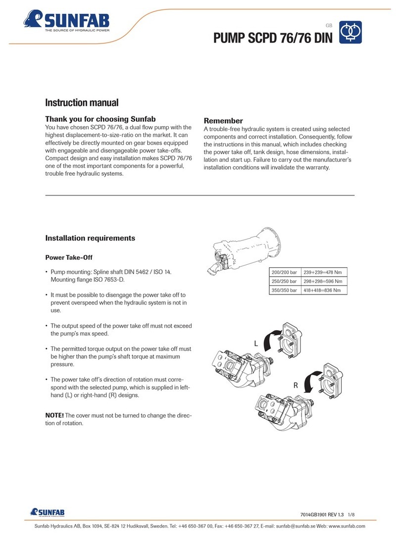
You have chosen SCPD 76/76, a dual flow pump with the
highest displacement-to-size-ratio on the market. It is
used together with a gearbox mounted power take-off.
Compact design and easy installation makes SCPD 76/76
one of the mainstays for powerful, trouble free hydraulic
systems.
REMEMBER
A trouble-free hydraulic system is created using selected
components and correct installation. Consequently, follow
the instructions in this manual, which includes checking
the power take off, tank design, hose dimensions, installa-
tion and start up. A correct installation is a prerequisite for
Sunfab’s warranty conditions.
INSTALLATION REQUIREMENTS
POWER TAKE-OFF
• Pump mounting according to ISO 7653-D
• The output speed of the power take off must not exceed
the pump’s max speed = 1700 rpm
• The permitted torque output on the power take off must
be higher than the pump’s shaft torque at maximum
pressure
• The power take off’s direction of rotation must correspond
with the selected pump, which is supplied in left-hand (L) or
righthand (R) designs
NOTE! The cover must not be turned to change the direc-
tion of rotation.
L
R
200/200 bar 239+239=478 Nm
250/250 bar 298+298=596 Nm
350/350 bar 418+418=836 Nm

Sunfab Hydraulics AB, Box 1094, SE-824 12 Hudiksvall, Sweden. Tel: +46 650-367 00, Fax: +46 650-367 27, E-mail: sunfab@sunfab.se Web: www.sunfab.com
1407 2/8
PUMP SCPD 76/76 DIN
INSTALLATION REQUIREMENTS (Continued)
OIL TANK
The design of the tank is important so that air bubbles are
not drawn into the pump and on into the system. Here are
two recommended designs:
1. Air bubbles from the return oil are guided by the oil flow
up to the oil surface (venting area) via an oil pipe mounted
at the bottom of the tank. Another option, yet not as reliable,
is a tank with a solid baffle plate as shown in the middle
picture
2. The drainage hose is connected close to the bottom, as
far as possible from the suction connection
3. Large return filter corresponding to 4 x the pump flow
4. Separate air filter, which is fitted protected from water and
dirt
5. Suction connection close to or in the bottom of the tank
on the opposite side to the return filter
6. The net volume of the tank should be at least 1.5 x the
pump flow and positioned so that the oil level lies above the
pump
A traditional tank fitted with a baffle plate with holes is not
recommended as this does not deaerate the oil satisfactorily.
SUNFAB OIL TANK
This tank is included in the Sunfab range of accessories.
It incorporates the latest advances in tank design to give
trouble-free operation.
The tank is available in two material options: stainless steel
and aluminium.
Pressure relief valves
The hydraulic system must be equipped with a pressure
relief valve for each circuit. The pump’s maximum pressure
is 350 bar.
All dimensions, internal diameter
Max flow 185 lit/min 255 lit/min
Max speed 1 230 rpm 1 700 rpm
Suction line 64 mm (2½”) 75 mm (3”)
Shut off valve 64 mm (2½”) 75 mm (3”)
Return line 38 mm (1½”) 45 mm (1¾”)
Pressure line 19 mm (¾”) 25 mm (1”)
1
2
3
4
5 6
Optional design, solid baffle plate.
Recommended design.
Non-recommended design.
di
If the suction line is more than 2
m long the internal diameter must
be increased by 10 mm for each
meter extension.
Recommended design
Optional design, solid baffle plate
Non-recommended design

Sunfab Hydraulics AB, Box 1094, SE-824 12 Hudiksvall, Sweden. Tel: +46 650-367 00, Fax: +46 650-367 27, E-mail: sunfab@sunfab.se Web: www.sunfab.com
1407 3/8
PUMP SCPD 76/76 DIN
INSTALLATION REQUIREMENTS (Continued)
HYDRAULIC OILS
Quality
Mineral oil
Use a high quality oil whose technical properties conform,
as a minimum, to the following requirements:
ISO type HM VG 32-68 depending on the ambient air
temperature. Alternatively DIN 51524-2 HLP
Environment oil
Use synthetic ester that conforms to the same technical
requirements as the standards above
Oil filling - Oil changing
New hydraulic oil in a drum has too high an impurity level.
Filling should therefore be done with the help of a filter unit
or through the oil tank’s return filter
Do not mix oil of a different quality, viscosity or brand. This
will impair the technical properties of the oil
Viscosity
The viscosity of the hydraulic oil drops (the oil becomes
thinner) when the temperature rises. An ideal choice is an
oil with a high viscosity index (VI). A higher VI gives less
viscosity variation when the temperature changes
• At a viscosity higher than 1500 cSt (limit for cold start)
the pump cannot suck in oil
• At a viscosity lower than 10 cSt the lubrication capacity
is insufficient. System efficiency will also be impaired
• When there is a risk of the oil temperature in oil tank to
exceed 60 °C, an oil cooler must be used
A B CD
A
0-20 20 40 60 80 100 C
68
46
32
BCD
A B CD
Refers to oil
temperature
in pump
E.g. Hydraulic oil 32: The designation “32” denotes the viscosity is 32
cSt at 40 °C. Lowest start temperature is -23 °C and highest working
temperature 82 °C. Ideal working temperature is 35 - 55 °C.
A
B
C
D
NOTE! The diagram concerns hydraulic oil with viscosity index VI ≈180
The hydraulic system can be started but not loaded. Only circulation
pumping at idling speed 1500-700 cSt.
The system can be loaded 700-40 cSt.
Ideal working range 40-20 cSt.
Highest recommended operating temperature 20-10 cSt.
=
=
=
=

Sunfab Hydraulics AB, Box 1094, SE-824 12 Hudiksvall, Sweden. Tel: +46 650-367 00, Fax: +46 650-367 27, E-mail: sunfab@sunfab.se Web: www.sunfab.com
1407 4/8
PUMP SCPD 76/76 DIN
INSTALLATION REQUIREMENTS (Continued)
FILTERING
To invest in cleanliness is worthwhile:
• Halving the amount of particles doubles component life
• Halving the amount of particles reduces the degree of
malfunction by half
To conform to most market demands on operating relia-
bility and life span the impurity level of the oil should cor-
respond to class 16/13 as set out in ISO 4406.
Consequently, the hydraulic system is equipped with a
return filter and air filter with a degree of filtration equal to
10 μm absolute.
Furthermore, the hydraulic system should be equipped
with a pressure filter if necessary.
Changing the filter:
First change after 50 hours of operation. Then whenever
the filter pressure indicates too high a pressure at the
normal operating temperature for hydraulic oil.
A good rule is to change the air filter at the same time.
Contamination level 18/16/13
Max 64,000 particles > 5 μm/100 ml.
Max 8,000 particles > 15 μm/100 ml.
18/16/13 10 μm
absolute
After changing the filter,
run with the lowest pos-
sible flow for at least 5
minutes to ensure the filter
functions.

Sunfab Hydraulics AB, Box 1094, SE-824 12 Hudiksvall, Sweden. Tel: +46 650-367 00, Fax: +46 650-367 27, E-mail: sunfab@sunfab.se Web: www.sunfab.com
1407 5/8
PUMP SCPD 76/76 DIN
INSTALLATION
Pump installation
Lubricate the splined shaft before installation using assembly
paste intended for spline joints, e.g. Molykote G Rapid plus,
or the like. Do not hit the gear wheel/drive disc. Use an M12
stud bolt and sleeve when assembling the gear wheel. Use
an M12 stud bolt and washer when assembling the drive
disc.
Secure the gear wheel using a circlip or M12 bolt and
locking fluid.
Secure the O-ring and fit the pump on the power take-off.
The manufacturer of the power take-off may have different
requirements.
Connections
Secure the O-ring and tighten the suction connection bolts
crosswise. Tighten the hose using two heavy-duty hose
clips. To maintain the speed characteristics do not use a
strainer on the SC-pump. Use pressure connections with
flat seals against the pump for optimal strength. Do not use
connections with tapered threads.
Tank location and hose routing
The tank should be positioned as high and as close to the
pump as possible in order to create good suction conditions
for the pump. The suction pipe must be routed so that air
pockets cannot form to prevent cavitation and noise.
SCPD 76/76 is internally drained.
Start up
Start and run the pump unloaded at idling speed and allow
the hydraulic oil to circulate through the hydraulic system
for at least five minutes before the system’s functionality is
tested.
24 Nm
64
mm (2½")
75
mm (3")
G¾, 150 Nm
80 Nm
80 Nm
Fill the pump with
hydraulic oil.
The pump can be installed in 4 positions with the angle
upwards, downwards or to the side. When the angle is to
the side it is an advantage if the pump can be twisted so
that the suction connection is highest.
Fill the pump with hydraulic oil

Sunfab Hydraulics AB, Box 1094, SE-824 12 Hudiksvall, Sweden. Tel: +46 650-367 00, Fax: +46 650-367 27, E-mail: sunfab@sunfab.se Web: www.sunfab.com
1407 6/8
PUMP SCPD 76/76 DIN
TROUBLESHOOTING
Measures with malfunctioning hydraulic system
Fault Troubleshooting Cause Action
The equipment works jerkily Check whether the flow in pressure
hose from the pump pulsates. Oil
spots on the pump and suction
hose can indicate an air leakage
Check the oil level in tank
Check whether the oil foams
1. Pump not vented after installation
2. Air leakage on the suction hose
or pump
3. Oil level too low
4. Not optimal designed tank for
separation of air from the oil
5. Oil tank with too small air
venting area
1. Vent the pump
2. Repair the air leakage
3. Fill with oil
4. Replace the return filter with oil
pipe or tank with solid baffle plate
5. Change to a tank with a greater
air venting area
The equipment works jerkily when
starting and at a high pump speed
Check whether the pump cavitates.
This is noticeable through flow pul-
sations and noise from the pump
ceasing when the speed is lowered
1. Too small diameter on the suc-
tion hose
2. Crushing or restriction of the
suction hose
3. Oil too thick
4. Underpressure in the oil tank
1. Change to a suction hose with a
larger diameter
2. Remove the restriction
3. Change to an oil with a lower
viscosity
4. Change the air filter
The oil has an abnormally high
temperature
Run the pump unloaded at working
speed and measure the counter
pressure. Connect a pressure
gauge to the pressure hose close
to the pump. The pressure must not
exceed 2 MPa.
Check whether the pressure rises
to the correct value when a fun-
ction is run towards the stop
1. Too small a diameter or restric-
tion in the pressure or return hoses
2. Clogged pressure or return filter
3. Oil flow too great
4. Pressure relief valve tripped at
too low a pressure
5. Oil too thin
6. Oil tank too small
7. Oil level too low
8. High continuous power output
1. Change to hoses with a larger
diam eter; rectify the restriction
2. Replace the filter
3. Lower the speed or change to a
smaller pump
4. Adjust the valve or replace if
necessary
5. Change to an oil with a higher
viscosity
6. Change to a larger oil tank
7. Fill with oil
8. Fit an oil cooler
The equipment has a lack of power Check whether the pressure rises
to the correct value when a fun-
ction is run towards the stop
1. Pressure relief valve tripped at
too low a pressure
2. Defective directional control valve
1. Adjust the valve or replace if
necessary
2. Replace the directional control
valve
If oil leakage has occurred by a damaged shaft seal, ensure that no hydraulic oil has entered the gearbox!
Fault Troubleshooting Cause Action
The equipment runs abnormally
slowly when loaded
Connect a flow meter close to the
pump. Check the flow
1. The correct flow is obtained
when loaded
2. Abnormally low flow obtained
when loaded
1. Pressure relief valve tripped at
too low a pressure
2. Worn pump
1. Adjust the valve or replace if
necessary
2. Replace the pump
Noise from the pump 1-5. Check whether the pump
cavitates This is indicated by the
noise stopping when the speed
drops Check whether the noise
propagates in the hydraulic system
6. Check whether the noise can be
heard at all speeds
1. Too small diameter on the suc-
tion hose
2. Crushing or restriction of the
suction hose
3. Oil too thick
4. Underpressure in the oil tank
5. Worn pump
6. Not optimal designed tank for
separation of air from the oil
1. Change to a suction hose with a
larger diameter
2. Remove the restriction
3. Change to an oil with a lower
viscosity
4. Change the air filter
5. Replace the pump
6. Fit a return filter with oil pipe or
tank with solid baffle plate
Oil leakage from the pump Localise the oil leakage 1. Leakage from suction connection
2. Leakage from shaft seal
3. Leakage from air screws
1. Replace the O-rings and tighten
the hose clips
2. Replace the shaft seals
3. Replace the sealing washers and
tighten carefully (15 Nm)
The pump shakes (intermediate
shaft assembly)
Check whether the pump shakes,
despite the flow not pulsating, i.e.
the attachment does not jerk
1. Play on intermediate shaft
2. Incorrect joint angle on interme-
diate shaft
3. Imbalance on intermediate shaft
4. The universal joints are not in line
with each other
1. Replace the intermediate shaft
2. Ensure that the spindle on the
power take off and pump shaft are
parallel
3. Rectify the countershaft
4. Loosen and turn the spline
coupling so that the universal joints
are aligned with each other

Sunfab Hydraulics AB, Box 1094, SE-824 12 Hudiksvall, Sweden. Tel: +46 650-367 00, Fax: +46 650-367 27, E-mail: sunfab@sunfab.se Web: www.sunfab.com
1407 7/8
PUMP SCPD 76/76 DIN
TECHNICAL DATA SCPD 76/76 DIN
Sunfab Hydraulics AB, Box 1094, SE-824 12 Hudiksvall, Sweden. Tel: +46 650-367 00, Fax: +46 650-367 27, E-mail: [email protected] Web: www.sunfab.com
SCPD 76/76 DIN
Theoretical oil flow
at pump speed rpm 500
1000
1500
l/min
37.5 + 37.5 = 75
75.0 + 75.0 = 150
112.5 + 112.5 = 225
Displacement cm
3
/rev
75 + 75
Max pump speed
continuous
limited
rpm 1500
1700
Max working pressure bar 350
Weight kg 23.2
Tare-weight torque without valve Nm 34.5
Theoretical power at pressure and pump speed
rpm 500
1000
1500
200 Bar
12.5 + 12.5 = 25.0 kW
25.0 + 25.0 = 50.0 kW
37.5 + 37.5 = 75 kW
250 Bar
15.6 + 15.6 = 31.2 kW
31.3 + 31.3 = 62.6 kW
46.9 + 46.9 = 93.8 kW
350 Bar
21.9 + 21.9 = 43.8 kW
43.8 + 43.8 = 87.6 kW
65.6 + 65.6 = 131.2 kW
Nominal torque on pump shaft
at different pressures
200 Bar
239 + 239 = 478 Nm
250 Bar
298 + 298 = 596 Nm
350 Bar
418 + 418 = 836 Nm
Direction of rotation Left (L) or Right (R)
GB - Printed: 06/03/2014 14:44:39 - Page 3/4
SCPD 76/76 DIN

Sunfab Hydraulics AB, Box 1094, SE-824 12 Hudiksvall, Sweden. Tel: +46 650-367 00, Fax: +46 650-367 27, E-mail: sunfab@sunfab.se Web: www.sunfab.com
1407 8/8
PUMP SCPD 76/76 DIN
The Warranty certificate/Claim is a valuable document, which should be completed by the
mechanic after installation.
Applicable delivery conditions are Orgalime S 2000, with the following additions, unless
otherwise agreed.
• The warranty is valid for 12 months from when the product is put into operation, or a maxi-
mum of 18 months after the delivery date from SUNFAB
• The warranty is only valid when the pump is installed and used according to the Instruction
manual
• The warranty does not apply when the pump’s serial number is missing
• The warranty does not include labour costs when replacing the pump
• When making a claim the damaged pump should be sent with the completed warranty
certificate/claim form to SUNFAB. The claimant pays freight costs
• When the claim, after analysis of the pump by SUNFAB is not upheld, the claimant will be
charged costs for the claim analysis, corresponding to EUR100, and costs to return the pump
to the claimant
WARRANTY CONDITIONS FOR SCPD 76/76 DIN
When the pump is running:
1. Do not touch the pressure hose
2. Watch out for rotating parts
3. The pump and hoses may be hot
WARNING
This manual suits for next models
1
Table of contents
Other Sunfab Water Pump manuals
Popular Water Pump manuals by other brands

Stenner Pumps
Stenner Pumps S Series Installation and maintenance manual

Edwards
Edwards EOSi Series instruction manual

ARO
ARO CHOP-CHECK 650941-X-C Operator's manual

DRENO
DRENO Compatta M/T Installation and operating instructions

Piusi
Piusi SUPREME BY-PASS 3000 Installation, use and maintenance guide

Graco
Graco FD2 1590 Instructions-parts list