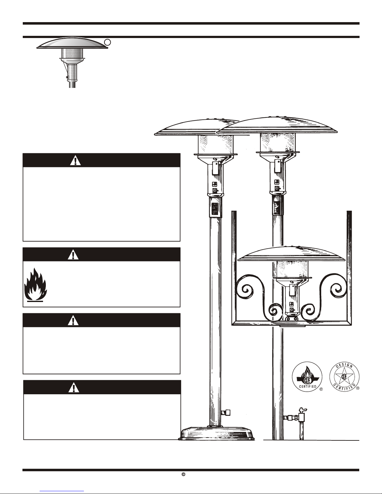
Sunglo Infrared Heaters
™
HEATER LAYOUT AND PATIO DESIGN
There are a number of WHERE TO LOCATE PATIO
considerations in determining the HEATERS:
type and number of heaters to be TM
Sunglo Heaters naturally attract
used and their location on your people to their infrared warm glow.
outdoor patio. Locate heaters where people can
readily gather, sit or stand comfortably,
and where furnishings can easily be
Concept of Patio Heating: Hot air is moved to best accommodate the
not an option for heating an outdoor radiating warmth.
patio so a patio heater uses radiant
heat like we receive from the sun.
Radiant Heat: Is the type of heat you
receive from a fireplace, potbelly
stove, or the sun. It is an infrared wave
length that heats objects without first
heating the intervening air. Unlike
ultra violet light there is no sunburn or CONTROL SYSTEMS:
sun tanning affect. Infrared will not Sunglo™ heaters are available with a
attract insects. variety of control systems from
m a n u a l c o n t r o l s r e q u i r i n g n o
Patio Heater: Is an unvented gas-
electrical connections to a 24 VAC
fired infrared heater designed to GENERAL RULES FOR fully automatic ignition and control
concentrate radiant heat in outdoor LOCATING HEATERS: s y s t e m ( s e e B a s i c L i g h t i n g
areas. TM
A Sunglo Patio Heater can operate I n s t r u ct i o n s o n p a g e 6 ) . I t i s
effectively to maintain comfort even in
Definition of Outdoors (For the recommended that when multiple
completely exposed areas, although
purposes of these instructions). An heaters are used, that the electrical
w e a t h e r p r o t e c t e d a r e a s a r e
ap p l i an ce i s c o n si de re d to be circuitry be arranged so heaters can
d e s i r a b l e . W e a t h e r a n d w i n d
outdoors if installed with shelter no be switched individually or in groups
protection allows the surrounding air
more inclusive than: to provide maximum flexibility for
to be warmed to enhance the direct
1. With walls on all sides, but with no heating the patio.
radiant warming effect.
overhead cover. Breezy Conditions:
2. Within a partial enclosure which TM
Sunglo heaters are designed to
includes an overhead cover and no work well under a variety of outdoor
more than two side walls. These conditions, however under certain
side walls may be parallel, as in a conditions they work better than
breeze way, or at right angles to others and under some conditions
each other. they should not be operated at all. The
heater can be operated under breezy
3. Within a partial enclosure which
conditions when the cross wind is 0-
includes an overhead cover and
10 mph. If heaters are mounted on the
three side walls, as long as 30
edge of a precipice or sea cliff where
percent or more of the horizontal
wind is directed upwards into the
periphery of the enclosure is
reflector hood, damage to the heater
permanently open.
can occur. Upward thrusts of wind can
also be caused by wind walls or
EFFECTIVE RANGE architectural elements near the
(COVERAGE): heater. The patio must be designed to
The comforting warmth from a single protect against this type of condition.
TM
Sunglo Heater will cover a 12' to 20'
TM
circle. The Sunglo is a “comfort” WHEN MULTIPLE
heater,” and the coverage is the area HEATERS ARE USED:
in which people will received a When more than one heater is used in
comforting amount of warmth. Some an area, it is generally preferable to
people will require more or less locate them close together. Multiple
warmth than others to be comfortable heaters located on 8' to 15' centers
and will either turn the heater up or give over lapping hea t p atterns
down, or move closer or farther away increasing the overall effective
as they desire. coverage for each heater.
7
15 Ft. 15 Ft.
SUGGESTED SPACING WHEN
MULTIPLE HEATERS
ARE USED:
Spacing For: WELL PROTECTED AREAS
AND MILD CLIMATIC CONDITIONS
12 Ft. 12 Ft.
Spacing For: SEMI EXPOSED AREAS
WITH AVERAGE WEATHER CONDITIONS
8 Ft. 8 Ft.
Spacing For: COMPLETELY EXPOSED AREAS
WITH SEVERE WEATHER CONDITIONS