5
INSTALLING YOUR SUNGRABBERTM
The ideal location for your SunGrabberTM system is a south-facing pitched roof closest to your pool equipment with enough space to
mount your panel(s). West-facing would be your second choice followed by east with north being the least desirable. Be certain that
trees or other structures do not shade the location you select. The effectiveness of your SunGrabberTM system is dependent on the
amount of direct sunlight. Survey the roof to confirm a proper fit.
Make certain to avoid shaded roof areas.
A 1 to 1 1/2 horsepower pump will generally handle installations up to 30 feet away from the pool equipment and one story high.
Large systems and remote installation may require a pump with more horsepower. If your pool has a gas heater or heat pump, plumb
your system in between the filter and gas heater/heat pump. Your should see a reduction in your monthly energy bill!
When transporting panel(s) to the roof or rack and while positioning panel(s) before mounting, be sure they are not
dragged over any sharp surfaces.
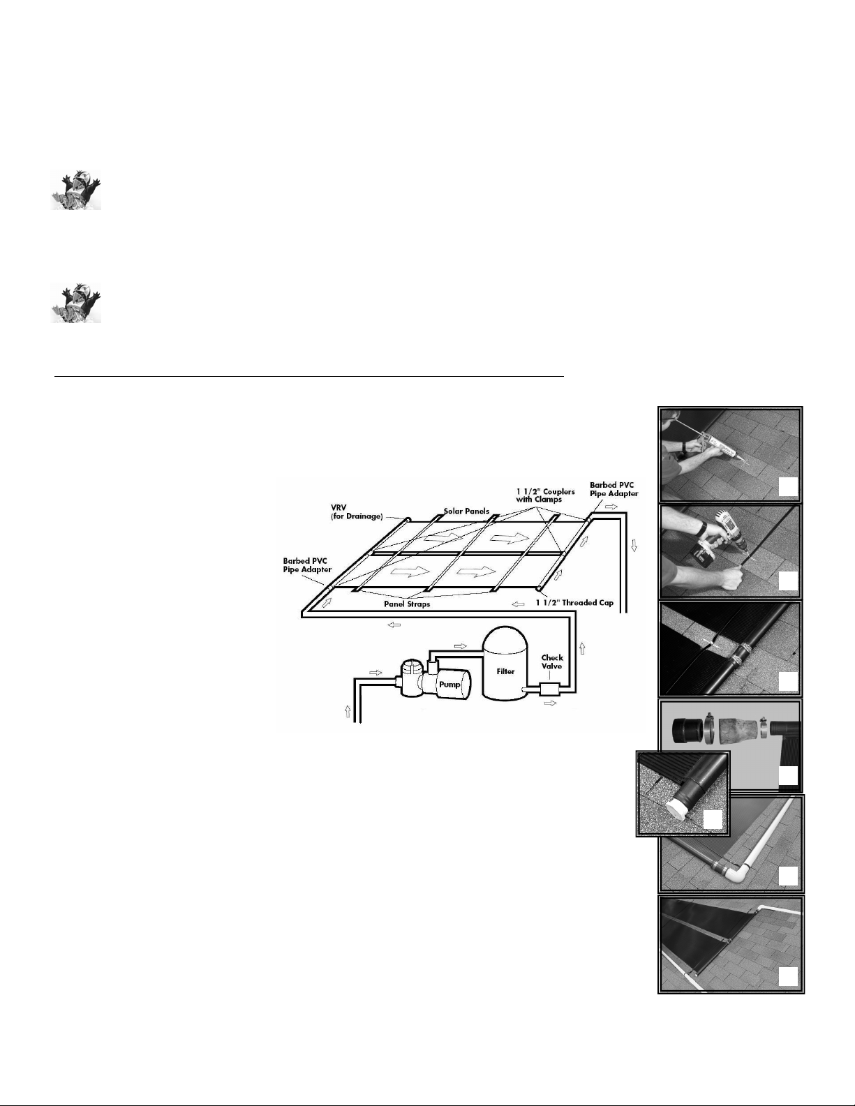
HORIZONTAL INSTALLATIONS ON ASPHALT SHINGLE ROOFS [20’ PANELS]
1. Determine the location of your panel(s). Lay out your system so that it declines slightly (about 1/4” of
fall every 10’) toward the bottom corner of the panel that feeds from your pool equipment. This is
needed to ensure proper drainage for winterizing.
2. The three mounting straps
provided should be positioned
with one in the center of the panel,
and one 5” in from each header.
Mark the bottom row lag bolt
locations. Position the first strap
with 10” of underhang below the
lag bolt location, drill an 1/8” pilot
hole, remove strap, apply
adhesive to the pilot hole, re-
position the strap, and screw the
lag bolt through the strap into the
roof. Install remaining two straps
the same way. In Step 10, you
will use the 10” underhang
strapping and the same lag bolt to
secure supply piping.
3. If this is a multiple panel system, connect all the panels using the rubber couplers and hose clamps
provided with your system. Make sure each coupler is pushed on at least an inch past the raised
ribs of the header adapters. Position hose clamps 1/4” from the end of the couplers and tighten.
4. Install the threaded PVC plug into the bottom corner adapter of the bottom panel that will not have
plumbing running to it. Be sure to use TeflonTM tape on the threads of the plug.
5. Install the VRV and bell reducer as shown onto the upper most corner of the top panel that will not
have plumbing running to it.
6. Install rubber couplers and clamps on the opposite corners that will receive plumbing. Insert 1-1/2”
Male Ribbed Adapters (MRAs) with barbs into the coupler and secure with a hose clamp.
7. Follow Steps 1 and 2 for mounting remaining straps.
8. Construct plumbing as shown. Use extra strapping at the bottom to hold supply piping.
4.
2.
2.
3.
8.
5.
8.