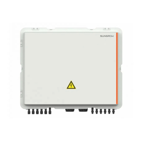
Sungrow EMS300 User manual

EEMMSS330000EEnneerrggyy MMaannaaggeemmeenntt
CCoonnttrroolllleerrUUsseerr MMaannuuaallEEMMSS330000––
UUEENN––VVeerr1100––220022220011
EMS300–UEN–Ver10–202201
EMS300
EEnneerrggyy MMaannaaggeemmeenntt CCoonnttrroolllleerr
UUsseerr MMaannuuaall


I
All Rights Reserved
AAllll RRiigghhttss RReesseerrvveedd
No part of this document can be reproduced in any form or by any means without the
prior written permission of Sungrow Power Supply Co., Ltd (hereinafter "SUNGROW").
TTrraaddeemmaarrkkss
and other Sungrow trademarks used in this manual are owned by
SUNGROW.
All other trademarks or registered trademarks mentioned in this manual are owned by
their respective owners.
SSooffttwwaarree LLiicceennsseess
•It is prohibited to use data contained in firmware or software developed by
SUNGROW, in part or in full, for commercial purposes by any means.
•It is prohibited to perform reverse engineering, cracking, or any other operations that
compromise the original program design of the software developed by SUNGROW.

II
About This Manual
This manual introduces the system in overview, diagram, operation step and examples
for you to understand and use this system flexibly and effectively.
The system is referred to as "EMS300" hereinafter unless otherwise specified.
TTaarrggeett GGrroouupp
This manual is intended for:
•Operators
•Managers
•Engineers
HHooww ttoo UUssee TThhiiss MMaannuuaall
This manual is briefly described by using the standard interface as an example. For
specific activated functions, refer to the content of the technical agreement or the
contract.
Contents may be periodically updated or revised due to the product development. The
manual content of subsequent versions of the product may be subject to change. The
latest manual can be found at ssuuppppoorrtt..ssuunnggrroowwppoowweerr..ccoomm .
SSyymmbboollss
Indicates additional information, emphasized contents or tips that may be
helpful, e.g. to help you solve problems or save time.
NNoottee
In order to provide customers with the best usage experience, the products and product
manuals are always in the process of improvement and upgrade. If the manual received
is slightly inconsistent with the product, it may be a result of product version upgrade,
and the actual product shall prevail.
The diagrams in this manual are for reference only. The actual product received may
differ.

III
CCoonntteennttss
All Rights Reserved.....................................................................................................I
About This Manual.....................................................................................................II
1 System Description ..................................................................................... 1
1.1 Introduction.................................................................................................. 1
1.2 Main Features.............................................................................................. 1
1.3 Requirements............................................................................................... 1
2 Login Steps .................................................................................................... 2
3 Web Main Interface .................................................................................... 4
4 Overview ........................................................................................................ 5
4.1 General Information ..................................................................................... 5
4.2 Current Alarms............................................................................................. 6
5 Device Monitoring and Maintenance .................................................... 7
5.1 Device Monitoring ........................................................................................ 7
5.2 Device Maintenance .................................................................................... 7
5.2.1 Add Device......................................................................................... 7
5.2.2 Edit Device ......................................................................................... 8
5.2.3 Delete Device ..................................................................................... 8
6 Control Method .......................................................................................... 10
6.1 Plant Lumped Parameter............................................................................ 10
6.2 Primary Frequency Modulation................................................................... 11
6.3 Voltage Control .......................................................................................... 13
6.3.1 Dynamic Reactive Voltage Regulation ............................................... 13
6.3.2 Fixed Value....................................................................................... 14
6.4 Active Power Control.................................................................................. 15
6.4.1 Fixed Value....................................................................................... 15
6.4.2 Planning Curve ................................................................................. 16
6.5 Reactive Control......................................................................................... 18
6.5.1 Fixed Value....................................................................................... 18
6.5.2 Planning Curve ................................................................................. 19
6.6 Stable Control/Fine Cut .............................................................................. 20

IV
6.7 Stabilize Fluctuations ................................................................................. 21
6.8 Multi Energy Coordination .......................................................................... 23
6.9 Supercritical Power Generation Prevention Control ..................................... 24
6.10 Power Distribution.................................................................................... 24
6.11 PID Control............................................................................................... 25
6.11.1 Active Power Parameters................................................................ 25
6.11.2 Reactive Parameters ...................................................................... 26
6.11.3 Voltage Parameters ........................................................................ 26
7 History Data ................................................................................................. 28
7.1 Operation Log ............................................................................................ 28
7.2 History Curve ............................................................................................. 28
7.3 Fault Records............................................................................................. 29
7.4 Dispatch Record ........................................................................................ 29
8 System .......................................................................................................... 30
8.1 Run Information ......................................................................................... 30
8.2 System Maintenance ................................................................................. 30
8.2.1 System Update................................................................................. 30
8.2.2 Log Export........................................................................................ 31
8.2.3 Rebooting......................................................................................... 31
8.2.4 Strategy Import................................................................................. 31
8.2.5 One-click Migration .......................................................................... 31
8.2.6 Reset All Setting................................................................................ 31
8.3 Remote Maintenance................................................................................. 32
8.4 Message Export......................................................................................... 32
8.5 System Time .............................................................................................. 33
8.6 Transfer Configuration................................................................................ 35
8.6.1 IEC104............................................................................................. 35
8.6.2 MODBUS.......................................................................................... 35
8.6.3 GOOSE ............................................................................................ 35
8.7 Port Parameter........................................................................................... 36
8.7.1 RS485.............................................................................................. 36
8.7.2 Ethernet ........................................................................................... 36
8.7.3 AI ..................................................................................................... 37
8.7.4 DI ..................................................................................................... 37
8.7.5 DO ................................................................................................... 37
8.8 System Mode............................................................................................. 38
8.9 license ....................................................................................................... 38

V
9 About ............................................................................................................. 40
10 Appendix .................................................................................................... 41
10.1 Quality Assurance .................................................................................... 41
10.2 Contact Information ................................................................................. 41


1
1System Description
1.1 Introduction
EMS300 is a web-based local monitoring system. Addressing the problems of unused
surplus wind and PV power, unstable loads, and different electric prices between peak
and off-peak hours, it balances power supplies and demands economically and
efficiently under different application scenarios and operation modes by optimizing
energy storage control and distributed power output and coordinating the
commissioning and ceasing of loads.
1.2 Main Features
SSmmaarrtt aanndd fflleexxiibbllee
Hierarchical and graphical display, support of flexible configuration display
SSiimmppllee aanndd eeffffiicciieenntt
•Second-based real-time data refresh
•Real-time alarm display, accurate fault positioning, efficient troubleshooting
SSaaffee aanndd rreelliiaabbllee
•Strict control procedure, complying with power system safety standards.
•Support dual mode/master and standby.
1.3 Requirements
IItteemm RReeqquuiirreemmeennttss
Browser Chrome 65 or above
Min. resolution 1920 x 1080

2
2Login Steps
step 1 Use the Ethernet cable to connect the PC to the EMS300.
step 2 Configure the IP address of the PC and that of the Ethernet ports (FE1 ~ FE4) of the
EMS300 to the same network segment. The IP address of the Ethernet port is shown
below. Taking port FE2&FE3 of controller 2 as an example, the default IP address of
Ethernet ports is 12.12.12.12. The IP address of the PC can be set to 12.12.12. X and
the subnet mask to 255.255.255.0.
table 2-1 IP address of controller 1
PPoorrtt DDeeffaauulltt IIPP VViirrttuuaall IIPP
FE1 14.14.14.14 —
FE2&FE3 13.13.13.13 15.15.15.15
FE4 12.12.12.12 —
table 2-2 IP address of controller 2
PPoorrtt DDeeffaauulltt IIPP VViirrttuuaall IIPP
FE1 14.14.14.15 —
FE2&FE3 12.12.12.12 15.15.15.15
FE4 13.13.13.13 —
The IP address of the above port is for reference only, please refer to the
actual one!
step 3 Enter the IP of the Ethernet ports in the address bar, to enter the default interface.
If you accidentally forget the IP address of the Ethernet ports, you can log in
with the virtual IP. The virtual IP of the Ethernet port is 15.15.15.15, available
for FE2&FE3 ports only.
step 4 Select the desired language in the upper right corner of the interface, and click LLooggiinn.
Enter the password pw1111 to access the web interface.
User types include ggeenneerraall uusseerr and OO&&MM UUsseerr.
The general user can view basic information, real-time fault, and device
monitoring information of the system.
In addition to all permissions of the general user, the O&M user has the
permission to set and modify parameters and control methods of the system.
In the following, description is given by using the O&M permission as an
example.

3
After login for the first time, it is recommended to change the password as
soon as possible. Click OO&&MM UUsseerr→→MMooddiiffyy PPaasssswwoorrdd to change the
password.
With the login password forgoten, contact SUNGROW and provide the device
S/N as well as system time, to get the password.
-- -- EEnndd
User Manual 2 Login Steps

4
3 Web Main Interface
The Web main interface is as follows:
IItteemm DDeessiiggnnaattiioonn DDeessccrriippttiioonn
A Navigation menu Display main function modules of the Web
B Function display
area
Display the current interface
CAlarm icon Display the current alarm level and alarm
number. Users can click the icons to enter the
corresponding alarm interface
D Language menu Click the button to select the desired language
E User Display the current login user
indicates the connection status of WLAN.
indicates the connection status of Ethernet port.
indicates the connection status of iSolarCloud.
The figure is for reference only. The actual interface may be different and shall
prevail.

5
4 Overview
4.1 General Information
Click OOvveerrvviieeww→→GGeenneerraall IInnffoorrmmaattiioonn to enter the corresponding interface.
The figure is for reference only. The actual interface may be different and shall
prevail.
PPllaanntt OOvveerrvviieeww
•PV
Users can view parameters such as real-time active power, available active power,
theoretical active power and real-time reactive power of the PV.
•ES
Users can view parameters such as real-time active power, real-time reactive power,
maximum discharging power allowed, available reactive power, maximum charging
power allowed of the ES.
•Grid
Users can view parameters such as plant total active power, total reactive power of
plant, frequency, bus voltage, power factor, etc.
IInnvveerrtteerr OOppeerraattiinngg MMooddee
Users can view the current mode of operation of the system.
AAccttiivvee PPoowweerr CCoonnttrrooll
Users can view output curves for parameters such as plant active power, active power
target value, energy storage active power and grid frequency.

6
RReeaaccttiivvee CCoonnttrrooll
Users can view output curves for parameters such as plant reactive power, reactive
power target value, reactive power of energy storage and bus voltage.
4.2 Current Alarms
Click OOvveerrvviieeww→→CCuurrrreenntt aallaarrmmss to view the device fault information.
The figure is for reference only. The actual interface may be different and shall
prevail.
Information such as alarm name, alarm type, alarm time and fault ID can be viewed.
Click FFaauulltt IIDD to see the corresponding solutions.
4 Overview User Manual

7
5Device Monitoring and Maintenance
5.1 Device Monitoring
Click DDeevviiccee MMoonniittoorriinngg to enter the corresponding interface.
The figure is for reference only. The actual interface may be different and shall
prevail.
•Click to select needed device type in the drop-down list.
•Select a device in the device list and view its real-time data on the right.
5.2 Device Maintenance
Click "DDeevviiccee→→DDeevviiccee lliisstt" to view the corresponding information.
The function module "DDeevviiccee lliisstt" is used for managing devices connected to the
system.
5.2.1 Add Device
step 1 Click DDeevviiccee→→DDeevviiccee lliisstt to enter the corresponding interface.
step 2 Click AAdddd ddeevviiccee, select a device type in the pop-up window, and fill in the information
required.
The figure is for reference only. The actual interface may be different and shall
prevail.

8
step 3 Click SSaavvee.
-- -- EEnndd
5.2.2 Edit Device
step 1 Click DDeevviiccee→→DDeevviiccee lliisstt to enter the corresponding interface.
step 2 Click the button in the operation bar, to modify the name, instruction internal time,
timeout value, repeat times of the devices connected to the system and other
parameters.
The figure is for reference only. The actual interface may be different and shall
prevail.
step 3 Click SSaavvee.
-- -- EEnndd
The DDeevviiccee NNaammee is named in the form device model (IP address-port
number-device address). Take EM610(10.7.3.136-502-1) as an example.
EM610 is device type, 10.7.3.136 is the IP address, 502 is the port number, 1
is the device address.
5.2.3 Delete Device
After a device is deleted on site, the user can delete the device from the device list, to
keep device consistency.
step 1 Click DDeevviiccee→→DDeevviiccee lliisstt to enter the corresponding interface.
step 2 Select the device to be deleted, click the button DDeelleettee.
5 Device Monitoring and Maintenance User Manual

10
6 Control Method
6.1 Plant Lumped Parameter
step 1 Click CCoonnttrrooll MMeetthhoodd→→PPllaanntt LLuummppeedd PPaarraammeetteerr to enter the corresponding interface.
The figure is for reference only. The actual interface may be different and shall
prevail.
step 2 Click to set the local/remote, dispatch interruption control method, priority, and
debug mode switch parameters.
PPaarraammeetteerr DDeessccrriippttiioonn
LLooccaall//RReemmoottee
Local
Enable the local mode when no need
to receive AGC or AVC dispatch
instructions
Remote
Enable the remote mode when need to
receive AGC and AVC dispatch
instructions
DDiissppaattcchh
iinntteerrrruuppttiioonn
ccoonnttrrooll mmooddee
Keep current value Keep the current value when
communication is interrupted
Zero power output Issue the zero power output instruction
when communication is interrupted

11
PPaarraammeetteerr DDeessccrriippttiioonn
PPrriioorriittyy
Reactive priority
Give priority to reactive power output
within the range of apparent power
limit
Active priority
Give priority to active power output
within the range of apparent power
limit
DDeebbuugg mmooddee
sswwiittcchh
Enable
Enable debug mode, and the power
distribution and slope control are
disabled. Power control instructions
will not be sent to the PCS or PV
inverters.
Disable Disable debug mode
RRaatteedd ccaappaacciittyy ooff
eenneerrggyy ssttoorraaggee
((MMWWhh))
Default value 0.100 Set the value according to actual
situation
step 3 Click DDiissppaattcchh BBaacckk--eenndd CCoonnffiigguurraattiioonn, enter the DDiissppaattcchh BBaacckk--eenndd CCoonnffiigguurraattiioonn
interface, set the DDiissppaattcchh IInntteerrrruuppttiioonn CCoonnttrrooll SSwwiittcchh status, and click CCoonnffiirrmm.
If DDiissppaattcchh IInntteerrrruuppttiioonn CCoonnttrrooll SSwwiittcchh is set to EEnnaabbllee, it is required to
enter the IP address of the dispatch background, and at most 2 IP addresses
can be entered.
step 4 Click SSaavvee.
-- -- EEnndd
6.2 Primary Frequency Modulation
This function can realize real-time grid-connected point frequency detection and
automatic control to keep the frequency within the safe range.
step 1 Click CCoonnttrrooll MMeetthhoodd→→PPrriimmaarryy FFrreeqquueennccyy MMoodduullaattiioonn to enter the corresponding
interface.
step 2 Click to set the status of FFuunnccttiioonn CCoommmmiissssiioonniinngg//CCeeaassiinngg and "SSeeggmmeenntt
NNuummbbeerr, Click SSaavvee.
User Manual 6 Control Method

12
The figure is for reference only. The actual interface may be different and shall
prevail.
step 3 Set the right frequency modulation parameters, which are described as shown below.
PPaarraammeetteerrss DDeessccrriippttiioonnss
fNRated frequency of grid-connection point
δ% Frequency regulation coefficient (δ%=-△f(%)/△P
(%))
fdFrequency modulation dead zone
PAMaximum output active power
PBMaximum active power PB absorbed
α1Lower limit of active power limit coefficient
α2Upper limit of active power limit coefficient
δ2% * Frequency modulation II regulation coefficient
fd2 *Frequency modulation II dead zone
* indicates the parameter to be set when the segment number = 5.
The active power limit coefficient is the absolute value of the ratio between the
output increment limit of the active power to the rated active power of energy
storage.
-- -- EEnndd
6 Control Method User Manual
Table of contents
Other Sungrow Controllers manuals
Popular Controllers manuals by other brands

Greenheck
Greenheck Belimo Actuators Direct Drive Series installation instructions

OEM
OEM SW-8SPKR quick start guide

Eaton
Eaton xComfort CSAP-01/XX Assembly instructions

Eaton
Eaton Intelligent Power Controller 3000 Installation and quick start manual

Mec
Mec ME 225 PowerTorq Series instruction manual

Kohler
Kohler Dongle 23777T installation instructions