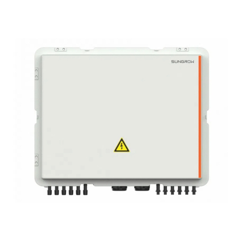
Sungrow BSC200 User manual

BBSSCC220000BBaatttteerryy SSyysstteemm
CCoonnttrroolllleerrUUsseerr MMaannuuaallBBSSCC220000--
UUEENN--VVeerr1100--220022220011
BSC200-UEN-Ver10-202201
BSC200
BBaatttteerryy SSyysstteemm CCoonnttrroolllleerr
UUsseerr MMaannuuaall


I
All Rights Reserved
AAllll RRiigghhttss RReesseerrvveedd
No part of this document can be reproduced in any form or by any means without the
prior written permission of SUNGROW ENERGY STORAGE TECHNOLOGY CO., LTD (-
hereinafter "SUNGROW").
TTrraaddeemmaarrkkss
and other Sungrow trademarks used in this manual are owned by
SUNGROW.
All other trademarks or registered trademarks mentioned in this manual are owned by
their respective owners.
SSooffttwwaarree LLiicceennsseess
•It is prohibited to use data contained in firmware or software developed by
SUNGROW, in part or in full, for commercial purposes by any means.
•It is prohibited to perform reverse engineering, cracking, or any other operations that
compromise the original program design of the software developed by SUNGROW.

II
About this Manual
This manual is aimed at providing the detailed product information and installation
operation and maintenance instructions for the BSC200 battery system controller.
Hereinafter it will be referred to as "BSC" unless otherwise specified.
TTaarrggeett GGrroouupp
This manual is intended for qualified persons responsible for the installation, operation,
and maintenance of the BSC and users performing routine operations.
Qualified personnel should have the following skills:
•Training for installation and commissioning of electrical system, as well as dealing
with hazards
•Knowledge of the manual and other related documents
•Knowledge of the local regulations and directives
HHooww ttoo UUssee TThhiiss MMaannuuaall
Read the manual and other related documents before performing any work on the
product.
Documents must be stored carefully and be available at all times.
Contents may be periodically updated or revised due to the product development. The
manual content of subsequent versions of the product may be subject to change. The
latest manual can be found at ssuuppppoorrtt..ssuunnggrroowwppoowweerr..ccoomm .
SSyymmbboollss
Important instructions contained in this manual should be followed during installation,
operation and maintenance of the product. They will be highlighted by the following
symbols.
Indicates a hazard with a high level of risk that, if not avoided, will result in death
or serious injury.
Indicates a hazard with a medium level of risk that, if not avoided, could result in
death or serious injury.
Indicates a hazard with a low level of risk that, if not avoided, could result in
minor or moderate injury.

III
Indicates a situation that, if not avoided, could result in equipment or property
damage.
Indicates additional information, emphasized contents or tips that may be
helpful, e.g. to help you solve problems or save time.
NNoottee
In order to provide customers with the best usage experience, the products and product
manuals are always in the process of improvement and upgrade. If the manual received
is slightly inconsistent with the product, it may be a result of product version upgrade,
and the actual product shall prevail.
The diagrams in this manual are for reference only. The actual product received may
differ.


V
CCoonntteennttss
All Rights Reserved.....................................................................................................I
About this Manual......................................................................................................II
1 Safety Instructions ...................................................................................... 1
1.1 Before Installation ........................................................................................ 1
1.2 During Installation......................................................................................... 1
1.3 Maintenance and Replacement.................................................................... 2
2 Product Description .................................................................................... 3
2.1 Function Introduction ................................................................................... 3
2.2 Appearance................................................................................................. 3
2.3 Dimension.................................................................................................... 4
3 Unpacking and Storage ............................................................................. 5
3.1 Scope of Delivery......................................................................................... 5
3.2 Identifying the Device................................................................................... 6
3.3 Checking upon Receiving............................................................................. 6
3.4 Storage........................................................................................................ 7
4 Mechanical Mounting ................................................................................ 8
4.1 Location Selection........................................................................................ 8
4.2 Installation Tools........................................................................................... 9
4.3 Installing the Device ..................................................................................... 9
4.3.1 Wall-Mounted Installation ................................................................... 9
4.3.2 Rack-Mounted Installation ................................................................ 11
5 Electrical Connection ............................................................................... 13
5.1 Safety Instructions...................................................................................... 13
5.2 Port Description.......................................................................................... 13
5.3 Communication Connection ....................................................................... 15
5.3.1 Ethernet Communication Connection................................................ 15
5.4 Earthing Connection................................................................................... 15
5.5 Connecting to the DC Power Supply ........................................................... 16
5.6 Connecting to the AC Power Supply ........................................................... 17
6 Commissioning ........................................................................................... 18

VI
6.1 Inspection before Commissioning............................................................... 18
6.2 Commissioning Steps................................................................................. 18
7 WEB Interface ............................................................................................ 19
7.1 Running Requirements............................................................................... 19
7.2 Preparations for Login................................................................................ 19
7.3 Login Steps................................................................................................ 19
7.4 WEB Main Interface ................................................................................... 20
7.5 View Running Information........................................................................... 21
7.6 Parameter Settings..................................................................................... 21
7.6.1 Overall Parameters ........................................................................... 21
7.6.2 System Parameters .......................................................................... 22
7.6.3 Communication Parameters ............................................................. 22
7.6.4 DCDC Parameters ............................................................................ 22
7.6.5 Liquid Cooling Unit Parameters ......................................................... 23
7.7 View History Records ................................................................................. 23
7.7.1 View Event Records.......................................................................... 23
7.7.2 Fault Records ................................................................................... 23
7.7.3 Alarm Records.................................................................................. 24
7.7.4 Running Records .............................................................................. 24
7.7.5 Rack Records................................................................................... 24
7.8 Version Information.................................................................................... 24
7.8.1 View Version Information .................................................................. 25
7.8.2 Firmware Upgrade ........................................................................... 25
7.8.3 Backup & Recovery .......................................................................... 25
8 Routine Maintenance ............................................................................... 26
8.1 Safety Precautions..................................................................................... 26
8.1.1 General Safety Rules ........................................................................ 26
8.1.2 Five Safety Rules.............................................................................. 26
8.2 Routine Maintenance ................................................................................. 27
9 Technical Data ............................................................................................ 28
10 Abbreviation Explanation ..................................................................... 29
11 Related Drawings .................................................................................... 30
12 General Information ............................................................................... 31
12.1 Quality Assurance .................................................................................... 31
12.2 Contact Information ................................................................................. 31

1
1Safety Instructions
This chapter mainly introduces some important safety instructions about operating the
device.
The device is designed and tested according to the international safety regulations. For
this electrical and electronic device, safety instructions related to it must be complied
with during installation, operation, and maintenance.
Incorrect operation or misoperation may cause:
•personal injury
•property damage
To prevent the personal injury and property damage and to ensure long-term operation
of the device, read these symbols carefully.
1.1 Before Installation
After receiving the device, check whether the device is damaged due to
transport. Should there be any problem, please contact us or the forwarding
company.
Before performing any operations on the device, the operators must be familiar
with all safety instructions and related regulations on installation, operation, and
maintenance.
Correct moving, transport, installation, operation and maintenance are critical to
safe and appropriate use of the device.
1.2 During Installation
The device can only be used as described in this manual. Unauthorized
alternation or using spare parts not sold or recommended by our company can
cause fires, electric shock, or other damage.

2
The device can only be used for the purposes specified in the manual.
Unauthorized modification or use of spare parts not sold or recommended by
the company may cause fire, electric shock, and other injuries.
Before the installation, disconnect all electrical connections and input switches
upstream to ensure that the device is voltage-free.
Before the electrical connection, disconnect input switches upstream, and
ensure that the device is voltage-free.
1.3 Maintenance and Replacement
•Only persons from the service department of our company or other qualified
personnel can service the device.
•The user is prohibited to perform maintenance, replacement, and other
operations. Otherwise, serious personal injury or tremendous property loss
may be caused.
Do not replace the internal components of the device without authorization. Our
company shall hold no liability for the damage caused.
1 Safety Instructions User Manual

3
2Product Description
2.1 Function Introduction
The BSC can collect battery information related to the battery clusters in the system and
upload this information to the energy management system to facilitate the management
of system information.
MMaaiinn FFuunnccttiioonnss
•Monitoring system BMS information
•Management system BMS fault alarm and other status
•Monitor liquid cooling unit information failure status
•Monitor the fault alarm status of the dry node
•Management system BMS and liquid cooling unit operating status
•Manage DO output control status
2.2 Appearance
IItteemm NNaammee DDeessccrriippttiioonn
A Indicator Display running status of the device
B Heat dissipation hole -
C Cable connection
terminal
-

4
table 2-1 Indicator
IInnddiiccaattoorr NNaammee DDeessccrriippttiioonn
PWR Power indicator
•PWR indicator is on: power supply is
normal
•PWR indicator is off: power supply is
abnormal
RUN Running indicator
•RUN indicator flashes: running is
normal
•RUN indicator is off: running is
abnormal
BLE Bluetooth indicator Reserved function
FAULT Fault indicator
•FAULT indicator is on: the system fault
occurs
•FAULT indicator is off: the system is
fault-free
2.3 Dimension
WWiiddtthh ((WW)) HHeeiigghhtt ((HH)) DDeepptthh ((DD))
440 mm 44 mm 241 mm
2 Product Description User Manual

5
3Unpacking and Storage
3.1 Scope of Delivery
Check for completeness of the scope of delivery according to the packing list in the
carton.
NNoo.. NNaammee DDeessccrriippttiioonn
A Device -
BEnclosed
documentation
User manual, delivery inspection records, packing list,
warranty card, and quality certificate
CCommunication
terminal resistor
12x120Ω
Note: When the RS485 bus is connected to more
than 15 devices, it is recommended to connect 120-
Ω terminal resistors in parallel to cables A and B on
the two ends of the bus
D Network Cable Length: 1x2m
EHanger 2
FBottom supporter 2
G OT terminal RNBL5-4
HNylon cable tie Fastening cables

6
NNoo.. NNaammee DDeessccrriippttiioonn
ITapping screw
assembly
8, including ST4.8x19 expansion bolts and tapping
screws, used for wall-mounted installation
JFastener assembly 6, M4x8 cross recessed countersunk head screws,
used to anchor the mounting ears to the device
3.2 Identifying the Device
The type and key technical parameters of the device can be found on the nameplate.
The nameplate is attached to the upper right corner of the device, shown by A in the
figure below.
The nameplate contains important parameters. Ensure it is intact and clearly
legible.
3.3 Checking upon Receiving
The device is thoroughly inspected and packed before delivery, but damage may be still
caused during transport. Check the following items carefully once receiving the device.
•Check the scope of delivery for completeness according to “Scope of Delivery” .
•Ensure that the device type is correct.
•Check the device thoroughly and ensure there are no visible damages.
If there are any problems, contact SUNGROW or the forwarding company.
Only undamaged device can be installed and commissioned. Before installation,
ensure that:
•The device is intact without any damages.
•Related documents, such as quick user manual, are enclosed.
3 Unpacking and Storage User Manual

7
3.4 Storage
If the device is not to be installed immediately after receiving, observe the following
requirements to store it properly:
•The device should be store in its original packing case and placed in a well-ventilated,
dry, and tidy room.
•The storage carrier should be suitable for the weight of the device.
•The storage environment should be well ventilated, dry, and without any
accumulated water.
•Ambient temperature: -40℃ to +85℃; relative humidity: 0~95%, no condensation.
•Take precautions to protect the device against damage due to harsh environment
such as shock cooling, shock heating, and collision.
•Regularly inspect the device, usually at least once a week. Check the packing case
for intactness and replace it immediately when necessary.
•Unpack and check the device in powered on state if it has been stored more than
half a year.
•The device must be packed during storage!
•Never store the device outdoors or in a place directly exposed to!
•No tilting or stacking!
After long-time storage, thoroughly check the device and ensure it is
undamaged before installation. If necessary, install the device only after it has
been tested by qualified personnel.
User Manual 3 Unpacking and Storage

8
4Mechanical Mounting
Respect all local standards and requirements during mechanical installation.
4.1 Location Selection
This section is intended to guide the user in selecting an appropriate installation location.
IInnssttaallllaattiioonn LLooccaattiioonn RReeqquuiirreemmeennttss
•With the ingress of protection IP 20, the device can be installed only indoors.
•Ambient temperature range: -30℃ to +60℃. The relative humidity should not exceed
95%. If otherwise, the internal components will be damaged.
•The installation environment should be free of inflammable, explosive, and corrosive
materials.
RReeqquuiirreemmeenntt ffoorr IInnssttaallllaattiioonn CClleeaarraannccee
Reserve enough clearances around the device.
Before installation, make sure the wiring terminals are at the bottom of the device to
prevent the dust or particles in the air penetrating into the device, impairing the service
life.
The installation location should be 1,500mm above the ground surface. Clearances of at
least 500mm should be reserved around the device for ease of maintenance. The follow
figure shows the requirement for minimum clearances.
When there are external devices (such as Meteo Station) connected to the
device, users should install corresponding communication SPD according to
onsite conditions.

9
4.2 Installation Tools
Installation tools include but are not limited to the following recommended ones. If
necessary, use other auxiliary tools on site.
4.3 Installing the Device
The device can be installed anywhere in the room meeting the installation environment
requirements. Wall-mounted installation and rack-mounted installation are supported.
4.3.1 Wall-Mounted Installation
Avoid drilling holes in the utility pipes and/or cables attached to back of the wall!
Turn on the vacuum cleaner and wear safety goggles and dust mask
throughout the drilling process to avoid dust inhalation or contact with eyes.
Installation component parts
User Manual 4 Mechanical Mounting

10
NNoo.. NNaammee NNoottee
1 Marker Beyond the scope of delivery
2 Hammer drill Beyond the scope of delivery
3 Bottom supporter In the scope of delivery
4 Mounting ear In the scope of delivery
5 Expansion bolt In the scope of delivery
6 Tapping screw In the scope of delivery
7Screwdriver Beyond the scope of delivery
IInnssttaallll MMoouunnttiinngg EEaarrss aanndd BBoottttoomm SSuuppppoorrtteerrss
Anchor the mounting ears and bottom supporters to the device with supplied M4x8
cross recessed countersunk head screws. The fastening torque is 1.8-2.4N·m, and
the anchoring method is as follows:
MMoouunntt tthhee ddeevviiccee ttoo tthhee WWaallll
step 1 Mark positions for drilling holes on the installation wall. Drill the holes with a hammer drill
of φ6mm. (Note: Reserve sufficient clearances around the device.)
step 2 Insert the expansion sleeve into the drilled hole, and make it completely embedded in
the wall with a rubber hammer.
step 3 Insert the tap screw and mounting ear successively into the expansion sleeve, to fix the
device onto the wall.
4 Mechanical Mounting User Manual

11
step 4 Fasten the tapping screw with a screwdriver by the torque of 0.3N·m.
-- -- EEnndd
4.3.2 Rack-Mounted Installation
Use 1U standard rack in case of the rack-mounted installation.
Installation tools and component parts
NNoo.. NNaammee NNoottee
1 1U standard rack Beyond the scope of delivery
2 Electric screwdriver Beyond the scope of delivery
3 Screw Beyond the scope of delivery
4 Nut Beyond the scope of delivery
IInnssttaallll MMoouunnttiinngg EEaarrss
Anchor the mounting ears to the device with supplied M4x8 cross recessed
countersunk head screws. The fastening torque is 1.8-2.4N·m, and the anchoring
method is as follows:
step 1 Mark positions on the rack according to dimensions of the device.
step 2 Drill holes on the rack with a hammer drill of φ6mm.
step 3 Level the mounting ears with the drilled holes on the rack.
User Manual 4 Mechanical Mounting
Table of contents
Other Sungrow Controllers manuals
Popular Controllers manuals by other brands

LAE
LAE AC1-2W Series Instructions for use

Robotis
Robotis XM540-W150 manual

Omron
Omron E5CK user manual

Buf Technology
Buf Technology ShowCase 3264 manual

Nord Drivesystems
Nord Drivesystems NORDAC LINK SK 155E-FDS Series user manual

Johnson Controls
Johnson Controls Metasys VMA1610 installation instructions

Siemens
Siemens SIMATIC Mobile Client900WXN operating instructions

SevenStar
SevenStar D07 Series instruction manual

TEL
TEL AFA1000/E MK2 Installation & Calibration Guide

SEFRAM
SEFRAM SDS3 quick start guide

Johnson Controls
Johnson Controls York 366-70488 Installation and Maintenance

TCS
TCS ISW6031-0145 quick start guide