manuals.online logo
Brands
  1. Home
  2. •
  3. Brands
  4. •
  5. Greenheck
  6. •
  7. Controllers
  8. •
  9. Greenheck Belimo Actuators Direct Drive Series User manual

Greenheck Belimo Actuators Direct Drive Series User manual

Installation Instructions
Belimo Actuators Direct Drive Series
(AMB, FSLF, LF, LMB, NMB, TF)
UL Listed Direct Drive Actuator
These instructions apply to the external field installation of Belimo actuators on Greenheck model VCD Control Dampers when
they are duct mounted or sleeved. For severe enivornment actuator kits, reference page 3 & 4.
Tools Required:
Wrenches:
(1) 3/8 in., (1) 7/16 in., and (1) 10mm
Part number 468753
!
!
CAUTION
Device Malfunction Hazard. Improper set screw tightening causes device malfunction. Tighten set screws
with proper torque to prevent damper shaft slippage.
!
!WARNING
Equipment Damage or Electrical Power Hazard. Line voltage can cause death or serious injury and short
equipment circuitry. Disconnect power supply before installation.
Item Part No. Qty Description
1 1 Belimo actuator
2 723092 1 Anti-rotation bracket
3 815027 1 Standoff bracket
4 415475 4 1/4 -20 x 1/2" bolt
5 415455 4 1/4-20 spinlock nut
6 415586 4 #14 TEK screw
7 416122 1 Anti-rotation pin
8 415385 1 Keps hex nut zp.
Instructions:
These installation instructions assume the damper is already
mounted in a duct or sleeve with the damper shaft extending
beyond the duct or sleeve 6 inches (152mm).
1. Install the stand off bracket.
Dampers with a jackshaft
1a. Mount the stand off bracket (item 3) onto the jackshaft
bracket with [4] 1/4 - 20 x 1/2 in. bolts (item 4) and [4]
1/4 - 20 spinlock nut (item 5) Orient the anchor bracket
perpendicular to the damper on the duct or sleeve so
that the bracket shaft hole is centered on the jackshaft.
Dampers without a jackshaft (Shaft Extension)
1b. Mount the stand off bracket (item 3) and extension pin,
as detailed in extension pin kit instructions, spanning
across the damper frame flanges. Orient the anchor
bracket perpendicular to the damper on the duct or
sleeve so that the bracket shaft hole is centered on the
shaft extension. Fasten to the damper frame with (4) #14
Tek screws or equal (item 6), supplied by others. Be sure
not to run the screws into the damper linkage, which is
between the flanges.
2. If the fail rotation of the damper is counter clockwise, this is a
Left Hand installation and the universal clamp should be on
the side labeled CCW on the actuator (usually shipped in this
orientation). If the fail rotation of the damper is clockwise, this
is a Right Hand installation and the universal clamp should be
on the side labeled CW on the actuator.
To change the universal clamp from one side to the other
side, remove the retaining clamp and then the universal clamp
from the actuator. Replace the universal clamp on the correct
side of the actuator making sure that the corresponding tab is
pointing to 0° and fits onto the actuator. Slip the clamp on and
then lock in place using the retaining clamp.
Note: All fail rotations refer to the damper shaft rotation
needed to achieve the desire blade fail position. If fail position
is closed, make sure damper blades are fully close and ensure
blade seals are compressed prior to tightening the actuator
clamp to the damper extension pin or jackshaft. Inspect the
damper blades and the damper shaft to determine the proper
damper shaft rotation for the desired blade fail position.
Orientation of Stand Off
Bracket for a directly driven
damper
Orientation of Stand Off
Bracket for a jackshaft
driven damper
Model Volts Running Holding
AMB24-3 24 2.5W 2.5W
AMB24-SR 24
FSLF24 24 5VA 3.5VA
FSLF24-S 24
FSLF120 120 18VA 6.5VA
FSLF120-S 120
FSLF230 230 17VA 6VA
FSLF230-S 230
LF24-SR 24 2.5W 1W
LF24-SR-S 24
LMB24-3 24
1.5W 1.5WLMB24-3-S 24
LMB24-SR 24
NMB24 24 2W 2W
NMB24-SR 24 2.5W 2.5W
TF24 24 2W 1.3W
TF24-S 24
TF120 120 2.5W 1.3W
TF120-S 120
TF24-SR 24 2W 1W
TF24-SR-S 24
3. Slide the actuator and the mounting bracket (item 2)
onto the damper shaft. Mount the mounting bracket
(item 2) to the stand off bracket (item 3) using (4) 1/4
in.-20 x 1/2 in. bolts (item 4), and (4) 1/4 in. - 20 Spinlock
nuts (item 5). Use the outer four holes of the mounting
bracket for jackshafted models and the inner four holes
for directly driven models.
Note: The mounting bracket (item 2) may be attached
in three positions: parallel with the duct, perpendicular
up from the duct, or perpendicular down from the duct.
Choose a position that offers the most clearance for the
application.
4. Verify that the damper is in its fail position. Tighten the
universal clamp to the damper shaft.
5. The wiring illustration is located on the face of the
actuator. Wiring should be per an approved project or
job wiring diagram and must comply with all applicable
electrical codes.
6. Apply power to the actuator. The damper blades should
fully open or close. No adjustments are required.
Tools Required:
Wrenches:
(1) 3/8 in., (1) 7/16 in., and (1) 10mm
These instructions apply to the external field installation of Belimo actuators on Greenheck model SEVCD Control Dampers
when they are duct mounted or sleeved
Item Part No. Qty Description
1 1 Belimo actuator
2 689990 1 Anti-rotation bracket 316SS
3 687784 1 Standoff bracket non-jackshafted units 316SS
4 687405 1 Standoff bracket jackshaft units 316SS
5 415475 8 CS 1/4-20 x 1/2" bolt 316SS
6 415702 8 1/4-20 hex nut 316SS
7 463888 1 Belimo mounting stud 316SS
8 415702 1 #10-32 SS nut
!
!
CAUTION
Device Malfunction Hazard. Improper set screw tightening causes device malfunction. Tighten set screws
with proper torque to prevent damper shaft slippage.
!
!WARNING
Equipment Damage or Electrical Power Hazard. Line voltage can cause death or serious injury and short
equipment circuitry. Disconnect power supply before installation.
Severe Environment (316SS)
Copyright © 2010 Greenheck Fan Corporation
468753 Belimo IOM Rev. 5 February 2010
Instructions for Severe Environment (316SS):
These installation instructions assume the damper is already
mounted in a duct or sleeve with the damper shaft extending
beyond the duct or sleeve 6 inches (152mm).
1. Install the stand off bracket.
Dampers with a jackshaft
1a. Mount the stand off bracket (item 4) onto the jackshaft
bracket with (4) 1/4-20 x 1/2 in. stainless steel bolts (item
5)and 1/4-20 hex nuts (item 6). Orient the anchor bracket
perpendicular to the damper on the duct or sleeve so
that the bracket shaft hole is centered on the jackshaft.
Dampers without a jackshaft (Shaft Extension)
1b. Mount the stand off bracket (item 3) and extension pin,
as detailed in extension pin kit instructions, spanning
across the damper frame flanges. Orient the anchor
bracket perpendicular to the damper on the duct or
sleeve so that the bracket shaft hole is centered on the
shaft extension. Fasten to the damper frame with (4)
1/4-20 x 1/2 in. stainless steel bolts (item 5) and 1/4-20
hex nuts (item 6). Be sure not to run the screws into the
damper linkage, which is between the flanges.
2. If the fail rotation of the damper is counter clockwise, this is a
Left Hand installation and the universal clamp should be on
the side labeled CCW on the actuator (usually shipped in this
orientation). If the fail rotation of the damper is clockwise, this
is a Right Hand installation and the universal clamp should be
on the side labeled CW on the actuator.
To change the universal clamp from one side to the other
side, remove the retaining clamp and then the universal clamp
from the actuator. Replace the universal clamp on the correct
side of the actuator making sure that the corresponding tab is
pointing to 0° and fits onto the actuator. Slip the clamp on and
then lock in place using the retaining clamp.
Note: All fail rotations refer to the damper shaft rotation
needed to achieve the desire blade fail position. If fail position
is closed, make sure damper blades are fully close and ensure
blade seals are compressed prior to tightening the actuator
clamp to the damper extension pin or jackshaft. Inspect the
damper blades and the damper shaft to determine the proper
damper shaft rotation for the desired blade fail position.
3. Slide the actuator and the mounting bracket (item 2)
onto the damper shaft. Mount the mounting bracket
(item 2) to the stand off bracket using (4) 1/4 in.-20 x 1/2
in. bolts (item 5), and (4) 1/4 in. - 20 Spinlock nuts (item
6). Use the outer four holes of the mounting bracket for
jackshafted models and the inner four holes for directly
driven models.
Note: The mounting bracket (item 2) may be attached
in three positions: parallel with the duct, perpendicular
up from the duct, or perpendicular down from the duct.
Choose a position that offers the most clearance for the
application.
4. Verify that the damper is in its fail position. Tighten the
universal clamp to the damper shaft.
5. The wiring illustration is located on the face of the
actuator. Wiring should be per an approved project or
job wiring diagram and must comply with all applicable
electrical codes.
6. Apply power to the actuator. The damper blades should
fully open or close. No adjustments are required.
Orientation of Stand Off
Bracket for a directly driven
damper
Orientation of Stand Off
Bracket for a jackshaft
driven damper

This manual suits for next models

27

Other Greenheck Controllers manuals

Greenheck PGD1000W00 User manual

Greenheck

Greenheck PGD1000W00 User manual

Greenheck MP-210 User manual

Greenheck

Greenheck MP-210 User manual

Greenheck Microprocessor Controller User manual

Greenheck

Greenheck Microprocessor Controller User manual

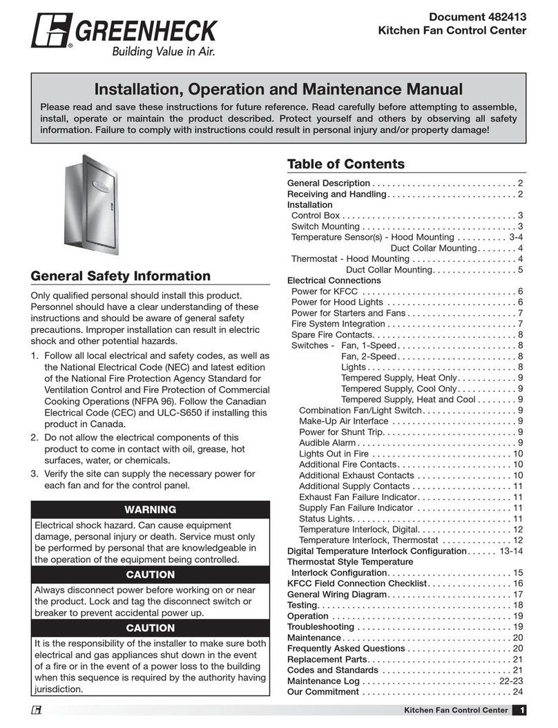
Greenheck KFCC User manual

Greenheck

Greenheck KFCC User manual

Greenheck DOAS v8.1 User manual

Greenheck

Greenheck DOAS v8.1 User manual

Greenheck MP-220A User manual

Greenheck

Greenheck MP-220A User manual

Greenheck vari-green Installation and operating instructions

Greenheck

Greenheck vari-green Installation and operating instructions

Greenheck HOA Troubleshooting guide

Greenheck

Greenheck HOA Troubleshooting guide

Greenheck MP-323 User manual

Greenheck

Greenheck MP-323 User manual

Greenheck MSXX04 Series User manual

Greenheck

Greenheck MSXX04 Series User manual

Greenheck MP-100A User manual

Greenheck

Greenheck MP-100A User manual

Greenheck MP-310 User manual

Greenheck

Greenheck MP-310 User manual

Greenheck HVLS Series User manual

Greenheck

Greenheck HVLS Series User manual

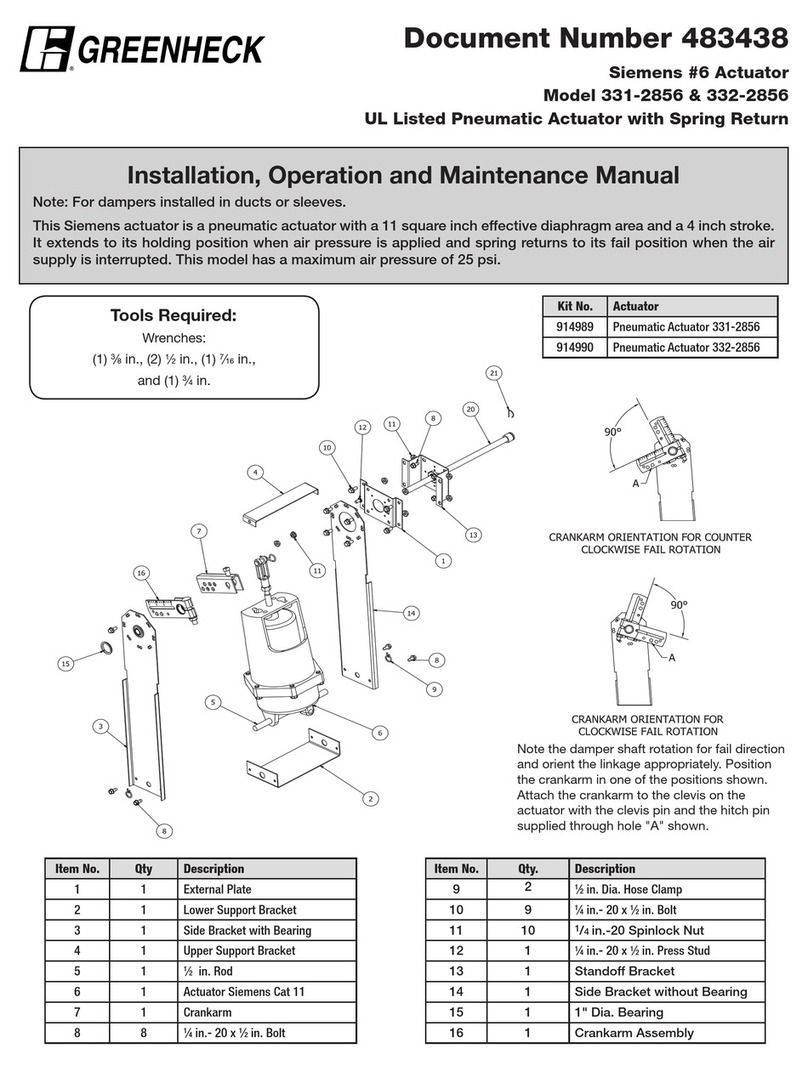
Greenheck 331-2856 Installation and operating instructions

Greenheck

Greenheck 331-2856 Installation and operating instructions

Greenheck 331-2976 Installation and operating instructions

Greenheck

Greenheck 331-2976 Installation and operating instructions

Greenheck MP-310 User manual

Greenheck

Greenheck MP-310 User manual

Greenheck MS-1P User manual

Greenheck

Greenheck MS-1P User manual

Greenheck HVLS User manual

Greenheck

Greenheck HVLS User manual

Greenheck 474706 User manual

Greenheck

Greenheck 474706 User manual

Greenheck MP-210 User manual

Greenheck

Greenheck MP-210 User manual

Popular Controllers manuals by other brands

Bacharach MGS-408 user manual

Bacharach

Bacharach MGS-408 user manual

Interpump Group Pratissoli RA2 operating instructions

Interpump Group

Interpump Group Pratissoli RA2 operating instructions

Resol deltasol bx plus manual

Resol

Resol deltasol bx plus manual

AUTOFLAME Mk8 MM End user guide

AUTOFLAME

AUTOFLAME Mk8 MM End user guide

Fisher 657 Sizes 80 instruction manual

Fisher

Fisher 657 Sizes 80 instruction manual

MAKOT UMS-02 user manual

MAKOT

MAKOT UMS-02 user manual

Westell DTWA528-28 Series manual

Westell

Westell DTWA528-28 Series manual

Mitsubishi Electric MELSEC iQ-F FX6U Hardware user manual

Mitsubishi Electric

Mitsubishi Electric MELSEC iQ-F FX6U Hardware user manual

Valcom PagePac V-5335100 quick start guide

Valcom

Valcom PagePac V-5335100 quick start guide

Matelec RPC-30030 Owner's operation manual

Matelec

Matelec RPC-30030 Owner's operation manual

Eaton COOPER POWER SERIES Installation and operation instructions

Eaton

Eaton COOPER POWER SERIES Installation and operation instructions

Siemens 125-1957 owner's manual

Siemens

Siemens 125-1957 owner's manual

RADSON TEMPCO Series Maintenance manual

RADSON

RADSON TEMPCO Series Maintenance manual

ABB AC500-S Application note

ABB

ABB AC500-S Application note

Siemens SIRIUS 3RW50 manual

Siemens

Siemens SIRIUS 3RW50 manual

Ametek ZF1 SSR Series Instruction, Operation and Maintenance Manual

Ametek

Ametek ZF1 SSR Series Instruction, Operation and Maintenance Manual

Elstat Nexo CMS200 product manual

Elstat

Elstat Nexo CMS200 product manual

MDT Technologies BE-GT2TW.01 operating instructions

MDT Technologies

MDT Technologies BE-GT2TW.01 operating instructions

manuals.online logo
manuals.online logoBrands
  • About & Mission
  • Contact us
  • Privacy Policy
  • Terms and Conditions

Copyright 2025 Manuals.Online. All Rights Reserved.