Sungrow PVS-18RM User manual

PVS-18RM-UEN-202010
PVS-18RM
PV Reverse Combiner Box
User Manual


Table of Contents
1About This Manual..............................................................1
1.1 Applicability ...............................................................................1
1.2 Brief introduction .......................................................................1
1.3 Intended audience.....................................................................1
1.4 Using this manual......................................................................2
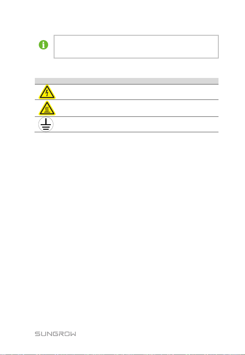
1.5 Symbols ....................................................................................2
2Safety instructions..............................................................4
3Product description ............................................................7
3.1 System introduction...................................................................7
3.2 Key features..............................................................................7
3.3 Appearance and structure.........................................................8
4Mechanical Installation.......................................................9
4.1 Scope of supply.........................................................................9
4.2 Dimensions ...............................................................................9
4.3 Storage....................................................................................10
4.4 Installation............................................................................... 11
4.4.1 Installation environment requirements..................................... 11
4.4.2 Installation tool preparation...................................................... 11
4.4.3 Installation method ..................................................................13
5Electrical Installation ........................................................14
5.1 System diagram overview .......................................................14
5.2 Internal structure .....................................................................15
5.3 Waterproof terminal.................................................................15
5.4 Preparation before wiring ........................................................16
5.5 Wiring......................................................................................17
5.5.1 Input wiring.............................................................................. 17
5.5.2 Output wiring...........................................................................20
5.5.3 Grounding ...............................................................................22

6Power Up/Down.................................................................25
6.1 Power up..................................................................................25
6.2 Power down.............................................................................25
7Routine Maintenance........................................................26
7.1 Replacing the fuse...................................................................26
7.2 Replacing the sealing strip.......................................................27
8Appendix............................................................................28
8.1 Basic parameters.....................................................................28
8.2 Warranty ..................................................................................28
8.3 Contact information..................................................................30

1
1 About This Manual
1.1 Applicability
This manual is applicable to PVS-18RM PV reverse combiner box which are
hereafter referred to as "combiner box" unless otherwise specified.
1.2 Brief introduction
This manual is intended for combiner boxes and covers the following:
Safety instructions
describes the safety precautions for operating and maintaining the combiner
box.
Product description
describes the overall dimensions and external composition of the combiner
box.
Installation
describes the mechanical installation and electrical connection of the
combiner box.
Routine Maintenance
describes how to replace the fuse of the combiner box.
Miscellaneous
describes the technical data, quality assurance clauses of the combiner box
and contact information.
1.3 Intended audience
This manual is intended for personnel who operate, maintain and perform other
work on the combiner box. The personnel who operate the combiner box
electrically should have knowledge of electricity and be familiar with the
electrical schematic diagram and the characteristics of the electronic
components.

1 About This Manual User Manual
2
1.4 Using this manual
Please read this manual carefully before using this product. Please put this
manual and other materials of the module together so that relevant personnel
can easily access it.
All contents, pictures, logos and symbols in this manual are the property of
SUNGROW. No part of this manual shall be reproduced, in whole or in part,
without written authorization by SUNGROW.
Descriptions in this manual are subject to changes and may differ from the
physical product. Please refer to the actual product purchased.
1.5 Symbols
This manual contains notices which you should observe to ensure your own
personal and property safety or to ensure efficient use and optimal product
performance. These notices are highlighted with appropriate symbols.
The symbols that may be used in this document are listed below. Please read
carefully to make better use of this manual.
"Danger" indicates high-risk potential hazards that, if not avoided, will
lead to death or serious injury.
"Warning" indicates moderate-risk potential hazards that, if not
avoided, may lead to death or serious injury.
"Caution" indicates a slightly hazardous situation which, if not
avoided, may result in minor or moderate injury.
"Note" indicates potential risks that, if not avoided, can lead to device
malfunction or financial losses.

User Manual 1 About This Manual
3
"Information" indicates additional information in the manual, which is
an emphasis or supplement to the manual and may provide tips for
users to better use the product, solve problems or save time.
Always pay attention to the hazard warnings on the machine, including:
Symbol
Description
indicates high voltage in the machine. touching it may cause electric
shock.
indicates the temperature exceeding the acceptable range for the
human body. It is prohibitted to touch it in order to avoid personal
injury.
indicates a protective ground terminal. This terminal should be firmly
grounded in order to ensure the safety of the operator.

4
2 Safety instructions
You are advised to read this chapter carefully before installing and using the
combiner box. SUNGROW assumes no responsibility or quality assurance for
any personal injury or device damage due to failure to observe these safety
precautions.
There is a high voltage in the PV string. Accidental contact may cause
fatal electric shock or severe burns. When wiring the combiner box,
you need to:
disconnect the end of the PV string before wiring.
follow the string manufacturer’s safety instructions.
Damaged device or system failure may cause electric shock or fire!
Before operation, visually check the device for damage or other hazards.
Check that other external devices or circuit connections are safe.
Make sure the device is safe before operating.
Touching the internal terminals of the device may result in electric
shock or fire!
Do not touch the terminals or conductors connected to the inverter or
string.
Pay attention to all instructions or safety documents regarding the
connection of the combiner box.

User Manual 2 Safety instructions
5
There may be a high voltage electric shock hazard inside the product!
Note and observe the warnings on the product.
Observe the safety precautions listed in this manual and other related
documents of this device.
The grounding cable must be well connected to ground, otherwise:
It may cause fatal electric shock to the operator in case of failure!
The device may be damaged when struck by lightning!
Incorrect cable connection can cause damage to PV modules,
combiner boxes, and inverters. When wiring, observe the following
precautions:
Wire according to the wiring drawing.
Before wiring, measure the open circuit voltage of the string to ensure that
the DC input voltage range meets the requirements of the combiner box.
Before wiring, check the positive and negative polarity of the string and
ensure that there is no ground fault.
Operation and wiring can only be done by professional electricians or
qualified personnel.
Operations and wiring must be done in accordance with relevant national
and local standards.
Warning signs must be legible and should be replaced immediately if
damaged.

2 Safety instructions User Manual
6
When wiring, make sure that the fastening screws of the combiner box
terminal are tightened in place. If the copper core of the cable cannot
be in full contact with the wiring terminal or pressed tightly, the
terminal would be heated and burned after a prolonged period.
Multi-strand copper core flame-retardant cables must be used, with the
wire diameter not less than the recommended value in the appendix.
The screw cap of the waterproof terminal must be fastened in place,
otherwise it may cause water leakage and damage the combiner box.
Do not check or replace the fuse with load! Installation and removal of
the fuse must be carried out with no load to avoid arc damage to the
device personal injury.
After operation, be sure to lock the door.
Do not open the door cover of the combiner box frequently to avoid
affecting its waterproof performance.

7
3 Product description
3.1 System introduction
The PV power generation system with combiner box is shown in Figure 3-1.
A B C D F
DC
AC
E
Figure 3-1 Composition of the PV grid-connected generation system
Table 3-1 Parts list
No.
Name
A
PV array
B
PV intelligent combiner box
C
PVS-18RM combiner box
D
Inverter
E
Transformer
F
Public power grid
3.2 Key features
Safety and reliability
PV special fuse, makes the system safer
C4 corrosion resistance level, high corrosion resistance level
Up to IP65
Flexible solution
Standard terminal design for ease of wiring
18-way terminal output, flexible design

3 Product description User Manual
8
Easy to operate and maintain
Light weight, easy to install and handle
3.3 Appearance and structure
The appearance of the DC combiner box is shown in the figure below.
AB
C
Figure 3-2 PVS-18RM appearance
No.
Name
Description
A
Door lock
-
B
Lug
Used to fix the combiner box
C
Waterproof terminal
-

9
4 Mechanical Installation
4.1 Scope of supply
A B C D
No.
Name
Description
Quantity
A
Reverse
combiner box
-
1
B
Related
documents
Including certificate, warranty card,
factory inspection report, etc.
1
C
Key
Used to open the combiner box door
1
D*
Waterproof
terminal
assembly
Including bottom cover and 4
waterproof terminals
1
* Optional
4.2 Dimensions
Width (W)
High (H)
Depth(D)
Width (W)
High (H)
Depth (D)
680 mm
400 mm
190 mm

4 Mechanical Installation User Manual
10
4.3 Storage
The combiner box should be stored under specific environmental conditions
when not in use:
The combiner box with the outer package should be stored in a ventilated,
dry, and clean indoor environment, with desiccant inside.
The container should be able to withstand the weight of the combiner box
with the package.
The number of stacks of multiple combiner boxes must not exceed the "stack
limit" marked on the outer box.
The packing box must not be inclined or upside down.
The storage environment should be well ventilated and free from moisture.
Accumulated water is not allowed in the storage environment.
Storage temperature range -40℃~+70℃, relative humidity range 0~95%, no
condensation.
Pay attention to possible hazards in the surrounding environment, such as
sudden temperature changes or collisions, to prevent any damage to the
combiner box.
The device which has been stored for more than half a year must be fully
inspected and tested by professionals before it can be put into operation.
Regular inspections, generally not less than once a week. Check that the
packaging is not damaged and prevent any damage that may be caused by
pests and animals. Replace the packaging immediately if it is damaged.
Storage without packaging is prohibited!
Storage outdoors or in direct sunlight is prohibited!
Tilt or stacking on the chassis is prohibited!
Before installing the combiner box which has been stored for a
prolonged period, a thorough inspection is required to ensure the
combiner box is in good condition. If necessary, it must be tested by
professionals before installation.

User Manual 4 Mechanical Installation
11
4.4 Installation
4.4.1 Installation environment requirements
The combiner box features IP65 and is suitable for outdoor or indoor installation.
The following requirements should be met:
The installation location should fully consider its dimensions and weight (see
the parameter chapter for details).
The installation environment temperature should be between -40℃~+60℃,
and the relative humidity should be between 0~99%. The combiner box
should be installed in a dry, well-ventilated and dust-proof place.
Never install the combiner box in a place exposed to direct sunlight,
otherwise the high temperature will reduce the yield of the system and may
also affect the service life of the combiner box.
For large-scale power plant projects, the combiner box should be installed in
a dark place on the PV module mounting bracket.
For better heat dissipation and ease of routine maintenance, sufficient space
should be reserved for installing the combiner box.
During the installation, moisture would cause damage to the combiner
box. Do not install the combiner box in rainy day or high air humidity.
After installation, the waterproof terminal must be tightened to prevent
water vapor from entering. After wiring, the unused terminals must be
blocked.
4.4.2 Installation tool preparation
General tools
Marker pen
Tape
Level ruler
Utility knife

4 Mechanical Installation User Manual
12
Multimeter
Range:
≥1000Vdc
880.0
Anti-static wrist
strap
Protective gloves
-
Dust mask
Sound insulation
earplugs
Goggles
Insulated shoes
Vacuum cleaner
Heat-shrink tube
Hot air gun
-
Installation tool
φ11 impact drill
M10 electric
screwdriver
M10 screwdriver
Wire stripper
Hydraulic clamp
Crimping tool
MC4 terminal
wrench
Wire cutter

User Manual 4 Mechanical Installation
13
4.4.3 Installation method
When installing the combiner box, fix it to the installation plane through the lugs
on its both sides. The hole distance of the lugs on its both sides is shown in the
figure below.
730
250
Wall mounting
Step 1 Measure the distance between the lugs on its both sides.
Step 2 On the plane on which the combiner box is to be installed, mark the
position of the mounting hole and drill.
Marking position Drill according to the mark
Step 3 Fix M10 bolts, flat washers, lugs, brackets, flat washers, spring washers,
and nuts in order. The torque is 34~40N.m.
4X

14
5 Electrical Installation
5.1 System diagram overview
A B C D F
DC
AC
E
12
3
Table 5-1 Device list
No.
Description
A
PV module
B
PV intelligent combiner box
C
Reverse combiner box
D
PV grid-connected inverter
E
Transformer
F
Power grid
Table 5-2 Cable designation
No.
Description
Wiring Method
1
Input cable, connect to PV
intelligent combiner box
Refer to “5.5.1 Input
wiring”
2
Output cable, connected to PV
grid-connected inverter
Refer to “5.5.2 Output
wiring”
3
Grounding Cable
Refer to “5.5.3 Grounding”

User Manual 5 Electrical Installation
15
5.2 Internal structure
Taking PVS-18RM for example, the internal structure of the combiner box is
shown in the figure below.
AB
CD
E
No.
Description
A
Positive output fuse box and fuse
B
Negative output fuse box and fuse
C
Positive input terminal
D
Negative input terminal
E
Grounding point
5.3 Waterproof terminal
Land pattern
Output DC+ Output DC-
Input DC+ Input DC-
There are two input waterproof terminals on the bottom of the standard
combiner box. To connect four waterproof input terminals, it is necessary to
install waterproof terminal assemblies. For details on installation, refer to the
figure below.

5 Electrical Installation User Manual
16
Waterproof terminal model
Tag
Description
Model
Cable OD
(mm)
INPUT DC+
Positive input waterproof
terminal
PGB25*
16~20
PGB29**
18~25
INPUT DC-
Negative input waterproof
terminal
PGB25*
16~20
PGB29**
18~25
Grounding waterproof
terminal
PG-16
10~14
OUTPUT DC+
Positive output waterproof
terminal
MGB24-H2
4.5~6
OUTPUT DC-
Negative output
waterproof terminal
*For the version with four input waterproof terminals.
**For the version with two waterproof terminals.
5.4 Preparation before wiring
Step 1 Open the combiner box.
1 2 3
Step 2 Remove the protective cover.
Step 3 Remove the fuse cover.
Table of contents
Other Sungrow Industrial Equipment manuals