Sunker elite four User manual

INSTRUKCJA OBSŁUGI
OWNERS MANUAL
MANUALULUTILIZATORULUI
HANDLEIDING VOOR GEBRUIKER
PL
EN
RO
NL
elite four

2
elite four
3
elite four
Spis treści
Rozdział 1
Specykacja techniczna
Rozdział 2
Instalacja
Instalacja radia
Zakłócenia pochodzące od układu zapłonowego
Antena
Głośnik zewnętrzny
Funkcja PA (Megafon)
Rozdział 3
Użytkowanie
Panel przedni
Panel tylny
Tabela częstotliwości
Odbiór i nadawanie
Wymiana mikrofonu i instalacja
Obsługa i montaż
Kilka zasad, które należy przestrzegać
Do czego może służyć CB radio
ROZDZIAŁ 1 SPECYFIKACJA TECHNICZNA
OGÓLNE
Model ELITE FOUR
Ilość kanałów 40
Zakres częstotliwości PL 26.960 – 27.400 MHz / EU 26.965 – 27.405 MHz
Typ modulacji AM
Kontrola częstotliwości Pętla fazowa PLL (Phase-Lock-Loop)
Stabilność częstotliwości 0.001%
Zakres temperatur -30stC - +50stC
Impedancja anteny 50 Om
Gniazdo antenowe Standardowe SO-239
Zasilanie 13.8V DC
Wymiary 184 x 229 x 57 mm
Waga 1.5kg
NADAJNIK
Moc wyjściowa RF 4W AM
Emisja sygnałów niepożądanych > -60dB
Zniekształcenie dźwięku < 5%
Pasmo przenoszenia 300 – 2500 Hz
Mikrofon Dynamiczny
ODBIORNIK
Czułość dla 10dB (S+N)/N < 0.5μV
Czułość Squelch < 0.5μV
Selektywność > -50dB
Tłumienie częstotliwości lustrzanych > 60 dB
Szumy i zakłócenia > -40 dB
Automatyczna Regulacja Wzmocnienia 50 mV dla 10 dB
Moc wyjściowa audio 2.5W przy zniekształceniach do 10%
Zakres częstotliwości Audio 300-2500 Hz
INSTRUKCJA OBSŁUGI
PL

4
elite four
5
elite four
ROZDZIAŁ 2 INSTALACJA
INSTALACJA RADIA
Miejsce zainstalowania radia w samochodzie powinno być dobrane tak, aby kierowca
(ewentualnie pasażer) mógł je swobodnie obsługiwać, jak też żeby nie przeszkadzało
ono w normalnym prowadzeniu samochodu, co jest bardzo ważne dla bezpieczeństwa
jazdy. Radio dostarczone jest z uniwersalnym mocowaniem. Kiedy uchwyt i radio zostaną
zamontowane w samochodzie, upewnij się czy mocowanie jest wytrzymałe. Zapewnij
także odpowiednie uziemienie. Postępuj zgodnie z instrukcją w celu poprawnego zain-
stalowania radia.
Wybierz odpowiednie miejsce do zainstalowania radia. Wywierć otwory na uchwyt radia.
Upewnij się czy korzystanie z radia nie będzie przeszkadzało w kierowaniu pojazdem.
Większość anten radiowych jest wyposażonych we wtyczkę PL-259. Podłącz ją do gniazda
ANT znajdującego się z tyłu radia.
Zaleca się podłączanie CB bezpośrednio do zacisków akumulatora. Czerwony przewód
do„+”instalacji, czarny przewód do„-”instalacji. Zmniejsza to w znacznym stopniu zakłó-
cenia spowodowane przez układ zapłonowy pojazdu.
(Radio to zostało zaprojektowane do samochodów z„minusem”na masie)
Uziemienia powinny być wykonane za pomocą uchwytów CRIMP o rozmiarach wystar-
czająco dużych do wykonania odpowiedniego połączenia ze śrubą służącą do połączenia
do baterii i do uziemienia. Dla bezpieczeństwa dobrze jest zainstalować drugi bezpiecz-
nik, który mógłby zapewnić dodatkową ochronę na wypadek, gdyby czerwony przewód
był zniszczony lub za krótki. Słabe połączenia zasilające mogą spowodować spadek na-
pięcia, co może znacznie zmniejszyć wydajność radia. Odpowiednie połączenie DC jest
jednym z najważniejszych elementów do otrzymania najlepszej wydajności nadajnika i
w niektórych przypadkach najmniejszych zakłóceń odbiornika
Umieść uchwyt mikrofonu blisko radia, w miejscu łatwo dostępnym
ZAKŁÓCENIA POCHODZĄCE OD UKŁADU ZAPŁONOWEGO
Gdy sygnał jest słaby mogą pojawić się szumy. Radio posiada ltry NB i ANL, które stoso-
wane są do zmniejszania szumów ze źródeł takich jak system zapłonowy. Jednakże, szu-
my mogą pochodzić z różnych źródeł i część z nich może nie udać się wyeliminować. Przy
bardzo słabym sygnale dobrze jest używać radia przy wyłączonym silniku, co powinno
poprawić odbiór. Jeżeli w większości warunków poziom zakłóceń jest zbyt wysoki, aby
zapewnić odpowiednie działanie, radio powinno być sprawdzone przez wykwalikowa-
ny serwis.
ANTENA
Radio posiada gniazdo standardowej wtyczki antenowej PL-259. Jeżeli radio ma praco-
wać w najlepszym zakresie transmisji zastosuj antenę ćwierćfalową o polaryzacji piono-
wej. Jeżeli antena jest dla Ciebie za długa możesz użyć krótszej, wtedy jednak możesz
spodziewać się spadku zasięgu. Aby polepszyć osiągi antena powinna być dostrojona
do radia.
GŁOŚNIK ZEWNĘTRZNY
Głośnik zewnętrzny należy podłączyć do gniazda jack EXT.SP. Głośnik zewnętrzny powi-
nien posiadać impedancję 8om i moc przynajmniej 4waty. Kiedy zewnętrzny głośnik jest
podłączony, głośnik wewnętrzny jest odłączony.
Funkcja PA (Megafon)
Aby użyć funkcji PA podłącz głośnik zewnętrzny do gniazda jack PA.SP. Sprawdź specy-
kacje dla odpowiedniego głośnika. Aby zapobiec sprzężeniu akustycznemu, trzymaj
mikrofon z dala od głośnika.
ROZDZIAŁ 3 UŻYTKOWANIE
PANEL PRZEDNI
Gniazdo mikrofonowe: Używane do podłączenia mikrofonu.
SQUELCH (blokada szumów): Pokrętło używane do eliminowania szumów słyszalnych z
odbiornika w momencie braku łączności. Przekręć pokrętło do końca w prawo, a następ-
nie powoli w lewo do momentu gdy szumy są niesłyszalne. Późniejszy obrót w prawo
zwiększy wartość, którą sygnał musi przekroczyć aby być słyszalny. Tylko najsilniejsze sy-
gnały będą odbierane po ustawieniu pokrętła maksymalnie w prawo.
ON/OFFVOL: Pokrętło włącza/wyłącza radio i reguluje siłę głosu. Aby włączyć radio prze-
kręć pokrętło w prawo, dalsze podkręcanie będzie zwiększało głośność odbiornika.
MIC GAIN: Regulacja wzmocnienia mikrofonu podczas transmisji oraz w trybie PA. Umoż-
liwia ustawienie wzmocnienia tak, że pełna moc podczas nadawania zostanie uzyskana
we właściwej odległości mówiącego od mikrofonu. W trybie PA, zmiany głośności doko-
nuje się również tym pokrętłem.
elite four

6
elite four
7
elite four
POWER: Pokrętło to pozwala użytkownikowi zmieniać moc wyjściową RF.
SWR LED: Kontrolka ta zaświeci się na czerwono, gdy SWR przekroczy 3:1. Wskaźnik SWR
3:1 nie jest dokładną wartością, jest to informacja, że należy sprawdzić dostrojenie anteny.
CHANNEL: Pokrętło to używane jest do wyboru kanału.
Miernik na przednim panelu: Miernik ten pozwala użytkownikowi na monitorowanie siły
sygnału wejściowego, mocy wyjściowej RF, poziomu SWR oraz poziom modulacji AM.
RF GAIN: Regulator wzmocnienia RF używany jest do redukowania siły sygnału radio-
wego RF.
DIMMER: Pokrętło to służy do regulacji poziomu podświetlenia miernika (8) i wyświetla-
cza kanałów (15).
SWR/MOD/PWR: Przełącznik ten służy do wyboru funkcji wskazywanych przez miernik.
Na pozycji SWR miernik pokazuje odczyt SWR (Standing Wave Ratio) czyli współczynnik
dopasowania anteny. Nie jest to współczynnik regulowany ponieważ w tym radiu SWR
kalibruje się automatycznie. Kiedy przełącznik ustawimy w pozycji MOD zielona skala na
mierniku wskaże głębokość modulacji AM w procentach. Najlepsze wskazanie będzie
przy maksymalnej mocy wyjściowej. Kiedy przełącznik ustawimy w pozycji PWR miernik
wskaże moc wyjściową.
NB-ANL/CB/PA: Kiedy przełącznik jest w pozycji NB/ANL ltry NB lub ANL zostają uru-
chomione. NB jest bardzo skuteczny w eliminowaniu powtarzalnych impulsowych zakłó-
ceń pochodzących m.in. od układu zapłonowego.W pozycji CB funkcja PA jest wyłączona
a radio będzie nadawało i odbierało przez podłączony głośnik. W pozycji PA radio działa
jako wzmacniacz rozgłoszeniowy (megafon). Dźwięk wychodzi z głośnika, który jest pod-
łączony do gniazda jack PA.SP znajdującego się na panelu przednim. Radio nie będzie
działało kiedy ustawione jest na pozycję PA.
TALKBACK: Właściwość ta wykorzystywana jest do monitorowania dźwięku. Na przy-
kład możesz wykorzystać tą funkcję w celu porównania różnych mikrofonów. HI oznacza
głośniej, LO oznacza ciszej. Dwutorowość zostanie wyłączona w momencie przełączenia
przełącznika na pozycję OFF.
RX/TX LED: RX - zielony wskaźnik odbioru, TX - czerwony wskaźnik nadawania.
Wyświetlacz kanałów: Pokazuje numer aktualnego kanału od 1 do 40.
PANEL TYLNY
ANT: Gniazdo antenowe, typ PL-259, kabel koncentryczny 50 Om.
DC 13.8V: Gniazdo zasilania 13.8V DC. Przewód zasilający radio posiada czarny i czerwo-
ny przewód. Czarny należy podłączyć do minusa a czerwony do plusa.
PA.SP: Gniazdo to służy do obsługi PA; do tego gniazda można podłączyć głośnik 8om,
4W lub większy.
EXT.SP: Gniazdo podłączenia zewnętrznego głośnika 4-8om, 5W. Kiedy zewnętrzny gło-
śnik jest podłączony, głośnik wewnętrzny jest odłączony.
F.C.: Gniazdo to służy do podłączenia 6-cyfrowego licznika częstotliwości.
Przełącznik kanałów PL/EU

8
elite four
9
elite four
TABELA CZĘSTOLTIWOŚCI PRZY USTAWIENIACH PRZEŁĄCZNIKA PL/EU ODBIÓR I NADAWANIE
A. Mikrofon
Przycisk na mikrofonie PTT służy do odbierania i nadawania. Wciśnij aby rozpocząć nada-
wanie, puść aby odbierać.
B. Odbieranie
Upewnij się czy źródło zasilania, mikrofon i antena są prawidłowo podłączone,
Przekręć pokrętło VOL w prawo aby włączyć radio,
Ustaw pokrętło VOL na odpowiedni poziom głośności,
Ustaw przełącznik MODE na odpowiedni tryb,
Posłuchaj szumów pasma z głośnika. Ustaw SQ tak, żeby przy braku sygnału wejściowe-
go szumu znikły. Odbiornik będzie teraz cichy, aż do momentu odebrania właściwego
sygnału. Nie„zaciągaj” blokady mocno, gdyż nie usłyszysz słabszych sygnałów,
Ustaw przełącznik kanałów CHANNEL na wybranym przez siebie kanale.
C. Nadawanie
Przełącznikiem kanałów CHANNEL ustaw odpowiedni kanał,
Ustaw regulator MIC GAIN do końca w prawą stronę,
Jeśli kanał jest czysty wciśnij przycisk PTT na mikrofonie i mów normalnym głosem.
WYMIANA MIKROFONU I INSTALACJA
Najlepsze rezultaty można uzyskać stosując mikrofon dynamiczny o małej impedancji lub mi-
krofon ze wzmacniaczem tranzystorowym. Mikrofon powinien posiadać przewód 4-żyłowy.
4-żyłowy przewód mikrofonowy
Numer Pin Żyła przewodu
1 Ekran
2 Żyła Audio
3 Załączenie nadawania
4 Załączenie odbioru
Rys.1 Schemat mikrofonu urządzenia nadawczo - odbiorczego
Jeżeli do używania mikrofonu trzeba przyciąć przewód należy postępować zgodnie
z zaleceniami:
Przetnij żyły tak, aby wystawały 7/16”(ok.10mm) poza izolację przewodu mikrofonowego
Wszystkie żyły powinny być przycięte na taką samą długość. Każdą końcówkę przewodu
należy oddzielić, a następnie ocynować wystające żyły.
Nr
kanału
Częstotliwość Nr
kanału
Częstotliwość
PL EU PL EU
126.960 MHz 26.965 MHz 21 27.210 MHz 27.215 MHz
226.960 MHz 26.965 MHz 22 27.220 MHz 27.225 MHz
326.980 MHz 26.985 MHz 23 27.250 MHz 27.255 MHz
427.000 MHz 27.005 MHz 24 27.230 MHz 27.235 MHz
527.010 MHz 27.015 MHz 25 27.240 MHz 27.245 MHz
627.020 MHz 27.025 MHz 26 27.260 MHz 27.265 MHz
727.030 MHz 27.035 MHz 27 27.270 MHz 27.275 MHz
827.050 MHz 27.055 MHz 28 27.280 MHz 27.285 MHz
927.060 MHz 27.065 MHz 29 27.290 MHz 27.295 MHz
10 27.070 MHz 27.075 MHz 30 27.300 MHz 27.305 MHz
11 27.080 MHz 27.085 MHz 31 27.310 MHz 27.315 MHz
12 27.100 MHz 27.105 MHz 32 27.320 MHz 27.325 MHz
13 27.110 MHz 27.115 MHz 33 27.330 MHz 27.335 MHz
14 27.120 MHz 27.125 MHz 34 27.340 MHz 27.345 MHz
15 27.130 MHz 27.135 MHz 35 27.350 MHz 27.355 MHz
16 27.150 MHz 27.155 MHz 36 27.360 MHz 27.365 MHz
17 27.160 MHz 27.165 MHz 37 27.370 MHz 27.375 MHz
18 27.170 MHz 27.175 MHz 38 27.380 MHz 27.385 MHz
19 27.180 MHz 27.185 MHz 39 27.390 MHz 27.395 MHz
20 27.200 MHz 27.205 MHz 40 27.400 MHz 27.405 MHz
TABELA CZĘSYOTLWOŚCI PRZY USTAWIENIU PRZEŁĄCZNIKA W POZYCJI EU ODPOWIADA NORMĄ I REGULACJĄ NARZUCONUM
PRZEZ UNIĘ EUROPEJSKĄ ODNOŚNIE CERTYFIKATU CE.
ODPOWIEDZIALNOŚĆ ZWIĄZANA ZE ZMIANĄ CZĘSTOTLIWOŚCI SPADA NA URZYTKOWNIKA.

10
elite four
11
elite four
Przed wykonaniem nowego okablowania przeczytaj uważnie informacje o obwodach i
instalacjach elektrycznych wybranego mikrofonu. Do lutowania połączeń używaj jak naj-
niższej temperatury. Aby zapobiec zwarciom, w momencie mocowania wtyczki, stosuj
kable jak najkrócej odsłonięte.
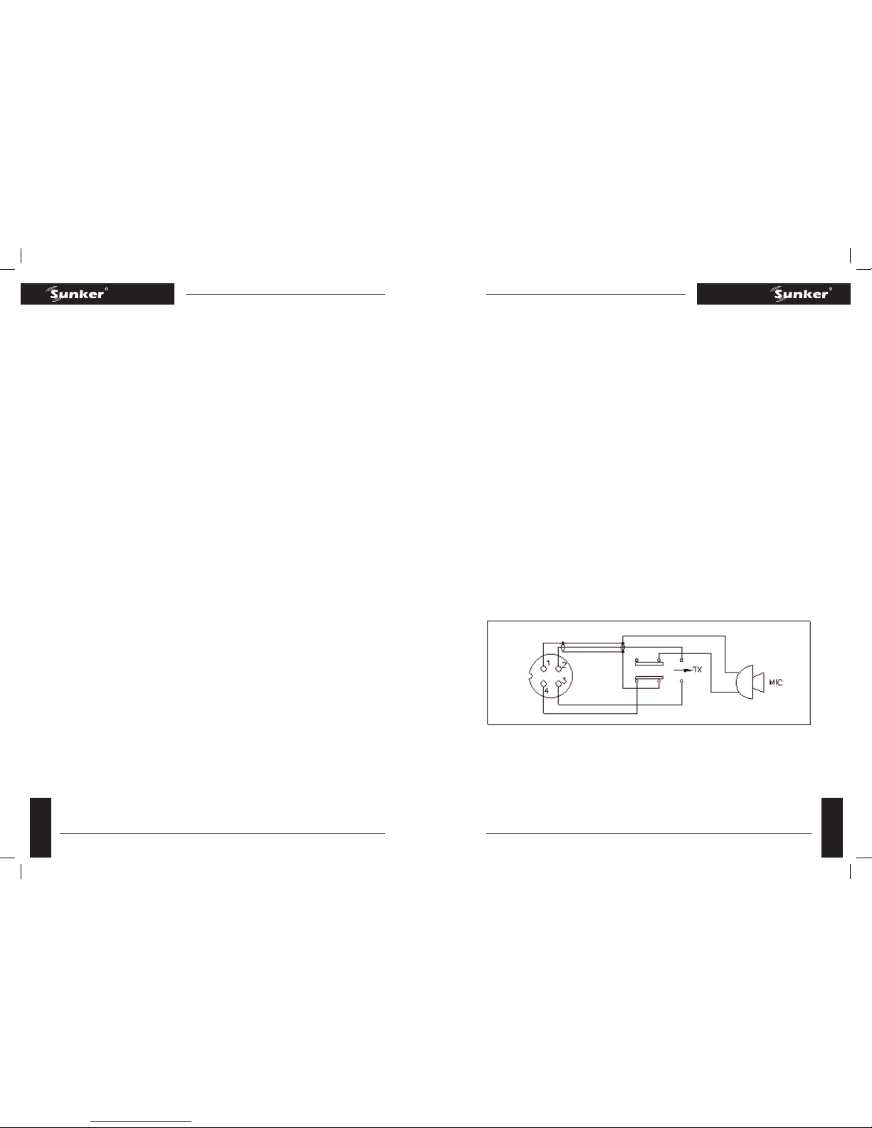
Rys.2 Schemat połączeń wtyczki mikrofonowej
Aby zmontować kabel mikrofonowy z wtykiem postępuj zgodnie z instrukcją:
Usuń śrubę mocującą
Rozluźnij dwa zaciski kabla trzymające śruby
Obróć w lewo osłonę metalową i oddziel ją od części bakelitowej
Włóż kabel mikrofonu do obudowy z nałożonym radełkowanym pierścieniem oraz pod-
kładkę na część bakelitową (tak jak na rys.2)
Teraz należy przylutować przewody do odpowiednich pinów, jak pokazano w powyższej
tabelce. Jeśli jest możliwość wykorzystania imadła lub mocowania należy je wykorzystać
do przytrzymania części bakelitowej podczas lutowania. Jeśli natomiast nie ma możli-
wości wykorzystania ani imadła ani mocowania, część bakelitową można podłączyć do
gniazda mikrofonowego znajdującego się z przodu radia. Numery gniazda mikrofonowe-
go przedstawione są na rys.3 jak również z tyłu wtyczki. Przed podłączeniem przewodów
do pinów należy wcześniej odpowiednio ocynować przewody gniazda z pinami wtyczki.
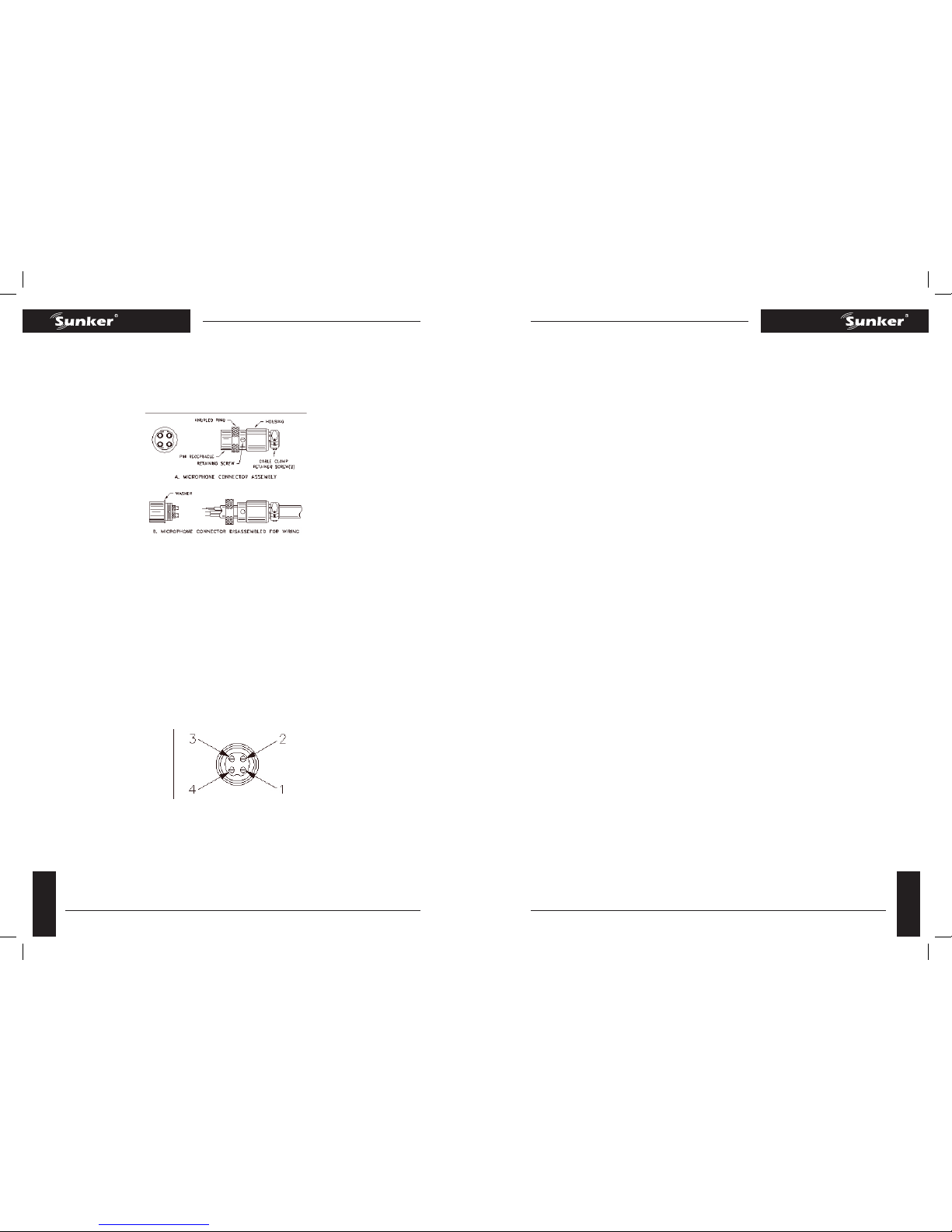
Rys.3 Numery pinów wtyku mikrofonowego pokazane na części bakelitowej
Przed rozpoczęciem lutowania upewnij się czy obudowa i radełkowany pierścień przed-
stawione na rys.2 nałożone są na kabel mikrofonowy. Jeśli podkładka nie jest przy obu-
dowie gniazda pinów upewnij się czy przed rozpoczęciem lutowania jest umieszczona na
nagwintowanej części bakelitowej.
Jeśli gniazdo mikrofonu używane jest do przytrzymania części bakelitowej podczas luto-
wania, najlepsze wyniki zostaną uzyskane kiedy połączenia do pinu 1 i 3 zostaną wykonane
jako pierwsze a dopiero potem połączenia pinów 2 i 4. Zastosuj jak najmniejszą ilość lutów
i unikaj nadmiernej ilości lutu na wtykach, może to spowodować zwarcie pomiędzy wty-
kiem a obudową gniazdka mikrofonowego.
Kiedy wszystkie lutowane połączenia wtyków mikrofonu zostaną wykonane, nałóż radełko-
wany pierścień i obudowę na nagwintowaną część bakelitową. Zwróć uwagę na lokalizację
gwintowanego otworu na obudowie wtyczki. Kiedy bakelitowa obudowa i część metalowa
są właściwie ustawione względem siebie, śruba trzymająca może zostać przykręcona.
Dokręć dwa wkręty zacisku kabla mikrofonowego.
Po zakończeniu montażu wtyczki mikrofonu podłącza i zabezpiecz go nakrętką.
KONSERWACJA I NAPRAWA
Urządzenie nadawczo - odbiorcze jest zaprojektowane do instalacji samochodowej. Ni-
ska waga urządzenia oraz zastosowanie solidnych obwodów elektrycznych wpływa na
wysoką niezawodność. W razie naprawy lub wymiany elementów należy zastosować
identyczne części, a nie części zastępcze.
Uwaga: Jeśli któreś funkcje opisane w rozdziale UŻYTKOWANIE nie działają, upewnij się,
czy wszystkie procedury opisane w instrukcji obsługi zostały prześledzone.
Uwaga: Wszystkie regulacje urządzenia, inne niż te możliwe do wykonania za pomocą
elementów umieszczonych na panelu przednim, muszą być wykonane pod nadzorem
osoby posiadającej licencję operatora radiotelefonu wydaną przez FCC.
KILKA ZASAD, KTÓRE NALEŻY PRZESTRZEGAĆ
Nie należy kontynuować rozmowy z inną stacją dłużej jak 5 minut bez minutowej prze-
rwy w mówieniu, aby dać innym szansę skorzystania z kanału,
Nie należy powodować zakłóceń u innych użytkowników poprzez przekraczanie dopusz-
czalnej mocy i używanie anten bez homologacji,
Nie należy używać nadajnika w celu reklamowania nielegalnych działań,
Nie należy używać wulgaryzmów,
Nie należy „puszczać”muzyki przez nadajnik,
Nie należy używać nadajnika w celu sprzedawania towaru ani profesjonalnej pomocy.
DO CZEGO MOŻE SŁUŻYĆ CB RADIO?
Ostrzeganie o wstrzymanym ruchu,
Przewidywanie pogody i udzielanie informacji drogowych,
Zapewnienie szybkiej pomocy podczas wypadku lub uszkodzenia samochodu,
Zaproponowanie dobrych miejsc na zjedzenie i spanie,
Sprawienie, że podróż będzie ciekawsza, pomaga nie zasnąć,
Zapewnienie bezpośredniego kontaktu z biurem/domem,
Poznanie ludzi podczas podróży,
Zapewnienie informacji o miejscu, do którego jedziemy,
Pomoc funkcjonariuszom prawa w odnajdywaniu pijanych oraz lekkomyślnych kierowców.

12
elite four
13
elite four
TABLE OF CONTENTS
CHAPTER 1
Specications
CHAPTER 2
Installation ..
Installing The Radio
Ignition Noise Interference
Antenna
External Speaker
Public Address
CHAPTER 3
Operation
Front Panel
Rear Panel
Frequency Chart
Procedure to Receive and Transmit
Alternate Microphone and Installation
Maintenance And Adjustment
A Few Rules That Should Be Obeyed
Use Channel 9 For Emergency Message Only
CHAPTER 1 SPECIFICATIONS
GENERAL
Model ELITE FOUR
Channels 40
Frequency Range 26.965 ~ 27.405 MHz
Emission AM
Frequency Control Phase-Lock-Loop (PLL) Synthesizer
Frequency Stability 0.001%
Temperature Range -30°C to +50°C
Antenna Impedance 50 Ohms
Antenna Connectors Standard SO-239 type
Input Voltage 13.8V DC
Size 7 1/4”(W) x 9” (D) x 2 1/4”(H)
Weight 3.4 lbs.
TRANSMITTER
RF Power Output AM: 4 watts
Spurious Emission > -60 dB
Unwanted Sideband -50 dB
Audio Distortion < 5%
Frequency Response 300 to 2500 Hz
Microphone Dynamic
RECEIVER
Sensitivity for 10 dB (S+N)/N < 0.5 uV
Squelch Sensitivity < 0.5 uV
Selectivity > -50 dB
Image Rejection > 60 dB
Hum & Noise > -40 dB
AGC Figure of Merit 50 mV for 10 dB Change in Audio Output
Audio Power Output 2.5W @ 10% Distortion
Audio Response 300 to 2500 Hz
(SPECIFICATIONS SUBJECT TO CHANGE WITHOUT NOTICE)
OWNERS MANUAL
EN

14
elite four
15
elite four
CHAPTER 2 INSTALLATION
INSTALLING THE RADIO
Choose a convenient location for operation that does not interfere with driver or passen-
ger.This radio is supplied with a universal mounting bracket. When mounting the bracket
and radio to your car, make sure it is mechanically strong. Also, provide a good electrical
grounding connection to the chassis of vehicle. Proceed as follows to install the radio.
Locate a convenient area in your vehicle for the installation of the radio. Hold the moun-
ting bracket with the radio in the location where the radio is to be installed. Make sure
nothing will interfere with either the radio or the mounting bolts. Mark and then drill
holes for the mounting bracket.
Most radio antennas come equipped with a PL-259 plug. Connect this plug to the ANT.
Jack in the rear of the radio.
Extending from the rear of the radio is a fused red and black wire for the DC connections
to the vehicle’s electrical system. For best performance, it is strongly recommended that
the red lead be taken directly to the positive terminal on the vehicle’s battery and the
black lead be connected to the nearest chassis ground. (Note: This radio is designed for
vehicles with negative ground systems.)
Connections should be made using appropriate“crimp on”lugs of a size large enough to
make good contact with the bolt used to fasten to the battery and the chassis ground.
It is a good safety idea to install a second fuse that would provide protection in case the
red wire was to “fray” or get pinched and short to the body of the vehicle, somewhere
between the battery and the radio.
Poor power connections cause supply voltage drops that can substantially decrease the
performance of your radio. A good DC connection is probably one of the most important
things for getting the best transmitter performance and in some cases, least receiver no-
ise.
Mount the microphone bracket near the radio in an easily accessible spot using the two
screws provided.
IGNITION NOISE INTERFERENCE
With weak signals, you may experience interference of the signal by background noise.
This radio has NB and ANL circuits which will help reduce background noise from sources
such as your ignition system. However, background electrical noise may come from se-
veral sources and all noise may not be eliminated. With extremely weak signals, you can
operate this radio with the engine turned o, which should improve reception. If the igni-
tion noise level is too high to allow proper operation under most conditions, you should
have your installation of the radio checked by a qualied technician.
ANTENNA
This radio has a jack in the rear for a standard PL-259 antenna plug. If you are looking for
the most range for your transmission, use a vertically polarized, quarter-wave length an-
tenna. If antenna height is a problem, you may use a shorter, loaded-type whip antenna
although you can expect some loss of transmission range.
To improve performance, your antenna should be matched to your radio. Your
antenna can be adjusted so that it matches your radio.
EXTERNAL SPEAKER
The external speaker jack (EXT SP.) on the rear panel is used for remote receiver monito-
ring. The external speaker should have 8 ohms impedance and be able to handle at least
4 watts. When the external speaker is plugged in, the internal speaker is disconnected.
PUBLIC ADDRESS
To use the Public Address (PA) function, rst connect an external speaker to the PA. SP.
Jack on the rear of the radio. See the above specications for a proper external speaker.
Keep the speaker away from the microphone to avoid acoustic feedback.
CHAPTER 3 OPERATION
CONTROL FUNCTIONS
FRONT PANEL
elite four

16
elite four
17
elite four
MICROPHONE JACK: Used to connect microphone for voice source.
SQUELCH CONTROL: This knob is used to eliminate background noise being heard thro-
ugh the receiver, which can be disturbing when no transmissions are being heard thro-
ugh the receiver. To use this feature, turn the knob fully counterclockwise and then turn
clockwise slowly until the background noise is just eliminated. Further clockwise rotation
will increase the threshold level which a signal must overcome in order to be heard. Only
strong signals will be heard at a maximum clockwise setting.
ON/OFF VOLUME CONTROL: This knob controls the volume and power to the radio. To
turn radio on, rotate the knob clockwise. Turning the knob further will increase the volu-
me of the receiver.
MIC GAIN CONTROL: Adjusts the microphone gain in the transmit and PA modes. This
controls the gain to the extent that full talk power is available several inches away from
the microphone. In the Public Address (PA) mode, the control functions as the volume
control.
POWER CONTROL: This control allows the user to adjust RF power output.
SWR LED: This LED lights red when your SWR is higher than about 3:1. This is not an exact
indicator of 3:1 SWR, but it is an indication that you should check your SWR reading.
CHANNEL SELECTOR: This control is used to select the desired transmit and receive
channel.
FRONT PANEL METER: The front panel meter allows the user to monitor incoming signal
strength, RF output power, SWR level and AM modulation level.
RF GAIN CONTROL: This control is used to reduce the gain of the RF (receive) amplier
under strong signal conditions.
DIMMER CONTROL: This knob controls the level of brightness for the meter lamp and
channel display.
SWR/MOD/PWR SWITCH: This switch controls the function of the meter during the
transmit mode. In the“SWR” position, the meter indicates the Standing Wave Ratio (SWR)
of your antenna. There are no adjustments because the SWR circuit in this radio calibra-
tes itself automatically. When the switch is in the“MOD” position, the green scale on the
meter indicates your percentage of modulation in the AM mode only. They are most ac-
curate when testing at maximum power output. When this switch is in “PWR” position,
the meter indicates your power output.
NB-ANL/CB/PA SWITCH: When the switch is in the NB/ANL position, the Noise Blanker
(NB) and Automatic Noise Limiter (ANL) circuits are activated. The Noise Blanker is very
eective in eliminating repetitive impulse noise such as ignition interference. In the CB
position, the PA function is disabled and the radio will transmit and receive on the spe-
aker that is connected. In the PA position, the radio acts as public address amplier. Your
voice will come out of the speaker that is plugged into the PA. SP. jack on the rear panel.
The radio does not operate when you are in the PA mode.
TALKBACK SWITCH: This is used to monitor your own voice. For example, you could use
this feature to compare dierent microphones. HI is high volume. LO is low volume. The
Talkback circuit is o when the switch is in the OFF position.
RX/TX LED: This LED is green during receive and red during transmit.
CHANNEL DISPLAY: The channel display indicates the current selected channel.
REAR PANEL
ANTENNA: This jack accepts a 50ohm coaxial cable with a PL-259 type plug.
DC POWER: This jack accepts the 13.8V DC power cable with built-in fuse. The power
cord provided with the radio has a black and red wire.The black goes to negative and red
goes to positive.
PA SP: This jack is for PA operation. Before operating, you must rst connect a PA speaker
(8 ohms, 4W) to this jack.
EXT. SP: This jack accepts a 4 to 8 ohm, 5watt external speaker. When the external spe-
aker is connected to this jack, the built-in speaker will be disabled.
F.C.: This jack is used to connect the optional six-digit frequency counter. All connections,
including DC power, are provided to the FC347 through this jack.

18
elite four
19
elite four
FREQUENCY CHART
Channel Channel Frequency Channel Channel Frequency
1 26.965 MHz 21 27.215 MHz
2 26.975 MHz 22 27.225 MHz
3 26.985 MHz 23 27.255 MHz
4 27.005 MHz 24 27.235 MHz
5 27.015 MHz 25 27.245 MHz
6 27.025 MHz 26 27.265 MHz
7 27.035 MHz 27 27.275 MHz
8 27.055 MHz 28 27.285 MHz
9 27.065 MHz 29 27.295 MHz
10 27.075 MHz 30 27.305 MHz
11 27.085 MHz 31 27.315 MHz
12 27.105 MHz 32 27.325 MHz
13 27.115 MHz 33 27.335 MHz
14 27.125 MHz 34 27.345 MHz
15 27.135 MHz 35 27.355 MHz
16 27.155 MHz 36 27.365 MHz
17 27.165 MHz 37 27.375 MHz
18 27.175 MHz 38 27.385 MHz
19 27.185 MHz 39 27.395 MHz
20 27.205 MHz 40 27.405 MHz
PROCEDURE TO RECEIVE AND TRANSMIT
MICROPHONE
The push-to-talk switch on the microphone controls the receiver and transmitter. Press
the switch and the transmitter is activated, release switch to receive. When transmitting,
hold the microphone two inches from your mouth and speak clearly in a normal voice.
This transceiver comes complete with a low impedance dynamic microphone.
PROCEDURE TO RECEIVE
Be sure that power source, microphone and antenna are connected to the proper con-
nectors before going to the next step.
Turn VOL knob clockwise to apply power to the radio.
Set the VOL for a comfortable listening level.
Set the MODE switch to the desired mode.
Listen to the background noise from the speaker. Turn the SQ knob slowly clockwise until
the noise just disappears. The SQ is now properly adjusted.The receiver will remain quiet
until a signal is actually received. Do not advance the control too far or some of the we-
aker signals will not be heard.
Set the CHANNEL selector switch to the desired channel.
PROCEDURE TO TRANSMIT
Select the desired channel of operation.
Set the MIC GAIN control fully clockwise.
If the channel is clear, depress the push-to-talk switch on the microphone and speak in
a normal voice.
ALTERNATE MICROPHONES AND INSTALLATION
For best results, the user should select a low-impedance dynamic type microphone or a
transistorized microphone. Transistorized type microphones have low output impedan-
ce characteristics. The microphones must be provided with a four-lead cable. The audio
conductor and its shielded lead comprise two of the leads. The third lead is for transmit
control and fourth is for receiving control.
The microphone should provide the functions shown in the schematic below.
4 WIRE MIC CABLE
Pin Number Mic Cable Lead
1 Audio Shield
2 Audio Lead
3 Transmit Control
4 Receive Control

20
elite four
21
elite four
Fig. 1 Your transceiver microphone schematic.
If the microphone to be used is provided with pre-cut leads, they must be revised as
follows.
Cut leads so that they extend 7/16”beyond the plastic insulating jacket of the micropho-
ne cable.
All leads should be cut to the same length. Strip the ends of each wire 1/8” and tin the
exposed wire.
Before beginning the actual wiring, read carefully the circuit and wiring information pro-
vided with the microphone you select. Use the minimum heat required in soldering the
connections. Keep the exposed wire lengths to a minimum to avoid shorting when the
microphone plug is reassembled.
Fig. 2 Microphone plug wiring
To wire the microphone cable to the plug provided, proceed as follows:
Remove the retaining screw.
Unscrew the housing from the pin receptacle body.
Loosen the two cable clamp retainer screws.
Feed the microphone cable through the housing, knurled ring and washer as shown Figure 2.
The wires must now be soldered to the pins as indicated in the above wiring tables. If
a vise or clamping tool is available it should be used to hold the pin receptacle body
during the soldering operation, so that both hands are free to perform the soldering. If a
vise or clamping tool is not available, the pin receptacle body can be held in a stationary
position by inserting it into the microphone jack on the front panel. The numbers of the
microphone plug are shown in Fig. 3, as viewed from the back of the plug. Before solde-
ring the wire to the pins, pre-tin the wire receptacle of each pin of the plug.
Fig. 3 Microphone plug pin numbers viewed from rear of pin receptacle.
Be sure that the housing and the knurled ring of Figure 2 are pushed back onto the mi-
crophone cable before starting to solder. If the washer is not captive to the pin receptacle
body, make sure that it is placed on the threaded portion of the pin receptacle body
before soldering.
If the microphone jack is used to hold the pin receptacle during soldering operation,
best results are obtained when the connections to pin 1 and 3 are made rst and then
the connections to pins 2 and 4. Use a minimum amount of soldering and be careful to
prevent excessive solder accumulation on pins, which could cause a short between the
pin and the microphone plug housing.
When all soldering connections to the pins of the microphone are completed, push the
knurled ring and the housing forward and screw the housing onto the threaded portion
of the pin receptacle body. Note the location of the screw clearance hole in the plug ho-
using with respect to the threaded hole in the pin receptacle body. When the housing is
completely threaded into the pin receptacle body, a nal fraction of a turn either clockwi-
se or counterclockwise may be required to align the screw hole with the threaded hole in
the pin receptacle body. When these are aligned, the retaining screw is then screwed into
place to secure the housing to the pin receptacle body.
The two cable clamp retainer screws should now be tightened to secure the housing to
the microphone cord. If the cutting directions have been carefully followed, the cable
clamp should secure to the insulation jacket of the microphone cable.
Upon completion of the microphone plug wiring, connect and secure the microphone
plug in the transceiver.

22
elite four
23
elite four
MAINTENANCE AND ADJUSTMENT
This transceiver is specically designed for the environment encountered in mobile installa-
tions.The use of all solid state circuitry and its light weight result in high reliability. Should a
failure occur, however, replace parts only with identical parts. Do not substitute.
NOTE
If the performance described in the OPERATION section is not
obtained, review the operating instructions to insure that pro-
per procedures were followed.
FCC WARNING
All transmitter adjustments other than those provided on
front panel by the manufacturer must be made by or under
the supervision of the holder of an FCC issued general radio
telephone operator’s license.
A FEW RULES THAT SHOULD BE OBEYED
You are not allowed to carry on a conversation with another station for more than ve
minutes at a time without taking a one-minute break, to give others a chance to use the
channel.
You are not allowed to blast others o the air by over-powering them with illegally ampli-
ed transmitter power, or illegally high antennas.
You can’t use the transceiver to promote illegal activities.
You are not allowed to use profanity.
You may not play music in your transceiver.
You may not use your transceiver to sell merchandise or professional services.
HOW YOUR CB CAN SERVE YOU
Warn of trac tie-ups ahead.
Provide weather and road information.
Provide help fast in event of emergency or breakdown.
Suggest good spots to eat and sleep.
Make long trips more interesting, and help keep you awake.
Provide direct contact with your oce or home.
Make friends for you as you travel.
Provide“local information”to nd your destination.
Help law enforcement ocers by reporting drunk and reckless drivers.
USE CHANNEL 9 FOR EMERGENCY MESSAGES ONLY
The FCC gives the following examples of permitted and prohibited types of communi-
cations for use in an emergency. These are guidelines and are not intended to be all in-
clusive.
Permitted Example Message
YES “A tornado sighted six miles north of town.
NO “This is observation post number 10. No tornado
sighted.
YES “I am out of gas on interstate 95”
NO “I am out of gas in my driveway”
YES “There is a four-car collusion at exit 10 on the Beltway,
send police and ambulance.”
NO “Trac is moving smoothly on the Beltway”
YES “Base to Unit 1, the weather Bureau has just issued a
thunder storm warning. Bring the sailboat into port.”
NO
“Attention all motorists. The weather Bureau advises
that the snow tomorrow will accumulate 4 to 6 inch-
es.
YES “There is a re in the building on the corner of 6th and
Main Streets.”
NO “This is Halloween patrol unit number 3. Everything
is quiet here.”

24
elite four
25
elite four
CUPRINS
SPeCIfICatII
INStalaRea
Instalarea radioului
Interferenta la pornirea contactului tena
Difuzor extern
Sonorizare exterioara
fUNCtIoNaRe
Panoul frontal
Panoul din spate
Tabelul frecventelor canalelor
Emisie – receptie .
Alegerea microfoanelor si instalarea
Intretinere si reglare
Cateva reguli de urmat
Utilizarea CB
Folosirea canalului 9 doar pentru mesaje de urgenta
SPeCIfICatII
GENERAL
Model DX 919
Canale 40
Gama de frecventa 26.965 ~ 27.405 MHz
Modulatie emisie AM
Controlul frecventei Sintetizator Phase-Lock-Loop (PLL)
Stabilitatea frecventei 0.001%
Gama de temperatura -30ºC pana la +50ºC
Impedanta antenei 50 Ohmi
Conectori antena standard SO-239
tensiunea de intrare 13.8V DC
Dimensiune 7 ¼” (W) x 9” (D) x 2 ¼” (H)
Greutate 3.4 lbs
TRANSMITATOR
Iesire putere RF AM:4 W
Difuzare falsa > -60dB
Banda laterala nedorita -50dB
Distorsiune audio < 5%
Raspuns in frecventa 300 pana la 2500 Hz
Microfon Dinamic
RECEPTOR
Sensibilitate pentru 10dB (S+N)/N < 0.5 uV
Sensibilitate la suprimarea zgomotu-
lui < 0.5 uV
Selectivitate >-50dB
Suprimarea frecventei imagine > 60dB
Zgomot >-40dB
Indicele de calitate AGC 50mV pentru o schimbare de 10dB la iesirea
Audio
Iesire audio 2.5W@ Distorsiune 10%
Raspuns audio 300 la 2500 Hz
(Specicatiile pot supuse modicarilor fara instiintare prealabila).
INSTALARE
INSTALARE RADIO
Alegeti in loc convenabil pentru functionare care sa nu interfereze cu activitatea soferului
sau cu pasagerii. Acest radio este echipat cu o placa de xare universala. Cand montati
MANUALULUTILIZATORULUI
RO

26
elite four
27
elite four
placa si radioul in masina, asigurati-va ca montarea este rezistenta din punct de vedere
mecanic. Asigurati de asemenea o conexiune electrica corespunzatoare a masei la sasiul
masinii. Procedati dupa cum urmeaza pentru a instala radioul:
Stabiliti o suprafata convenabila in masina pentru instalarea radioului. Tineti placa de xare
cu radioul in locul unde urmeaza sa e instalat radioul. Asigurati-va ca nimic nu va interfera cu
radioul sau cu suruburile de montare. Marcati si apoi efectuati gauri pentru placa de xare.
Majoritatea antenelor radio sunt echipate cu o sa tip PL-259. Conectati aceasta sa la
mufa ANT din spatele radioului.
Din spatele radioului se prelungeste un cablu prevazut cu sigurante rosu si negru pentru
conexiunile DC la sistemul electric al masinii. Pentru o performanta mai buna, se reco-
manda ca alimentarea cu + (rul rosu) sa e luat direct de la borna pozitiva a bateriei
masinii si cablul negru sa e conectat la masa cea mai apropiata.
(NOTA: Acest radio este conceput pentru masini cu minusul la masa.)
Conexiunile trebuie efectuate utilizand in mod adecvat saibe de dimensiuni destul de
mari pentru a efectua o conexiune corespunzatoare cu surubul folosit pentru conexiunea
la baterie si la sasiu. Este recomandabil sa instalati o a doua siguranta intre baterie si radio,
care sa ofere protectie in cazul accidental in care rul rosu face scurt la caroseria masinii.
O conexiune slaba poate provoca caderi de tensiune de alimentare care pot sa scada
substantial performantele radio. O conexiune DC buna este probabil unul dintre cele mai
importante lucruri pentru obtinerea celei mai bune performante a transmitatorului si in
unele cazuri, mai putin zgomot la nivelul receptorului.
Montati suportul microfonului in apropierea radioului intr-un loc usor accesibil folosind
cele doua suruburi furnizate.
INTERFERENTE LA PORNIRE
In cazul semnalelor slabe, pot aparea interferente de semnal cu zgomotul de fond. Acest
aparat radio are circuite NB si ANL, ceea ce va ajuta la reducerea zgomotului de fond
provenind de la surse cum ar sistemul de aprindere. Cu toate acestea, zgomotul electric
de fond poate proveni din surse diferite iar zgomotul nu poate eliminat complet. Cu
semnale foarte slabe, puteti pune in functiune aparatul radio cu motorul oprit, ceea ce
ar trebui sa imbunataseasca receptionarea semnalului. Daca nivelul de zgomot este prea
mare pentru a permite o functionare corespunzatoare in cele mai multe conditii, instala-
rea radioului ar trebui vericata de catre un tehnician calicat.
ANTENA
Acest radio are o mufa in spate pentru o priza standard a antenei PL-259. Daca doriti o
raza mai mare de transmisie, folositi o antena de sfert de unda polarizata vertical. Daca
inaltimea antenei este o problema, puteti folosi o antena mai scurta, cu toate ca va puteti
astepta la pierderi ale distantei de transmisie.
Pentru a imbunatati performanta, antena trebuie sa e reglata cu radioul. Antena poate
reglata astfel incat sa se potriveasca radioului.
DIFUZOR EXTERN
Mufa difuzorului extern (EXT SP.) de pe panoul din spate este utilizata pentru monitorizarea la
distanta a receptorului. Difuzorul extern ar trebui sa aiba o impedanta de 8 ohmi si sa poata su-
porta cel putin 4 Watti. Cand difuzorul extern este conectat , difuzorul intern este deconectat.
SONORIZARE EXTERIOARA
Pentru a utiliza functia de Sonorizare Exterioara (SE) conectati intai un difuzor extern la
SE. Mufa SP din spatele radioului. Observati specicatiile de mai sus pentru un difuzor
extern corespunzator. Tineti difuzorul la distanta de microfon pentru a evita efectul de
microfonie.
FUNCTIONARE
PANOUL FRONTAL
MUFA MICROFON: Folosit pentru a conecta microfonul.
SQUELCH: Acest buton este folosit pentru eliminarea zgomotului de fond ce poate auzit
prin receptor, lucru ce poate deranjant cand nu exista transmisii in curs. Pentru a folosi
aceasta caracteristica, rotiti butonul complet in sens contrar acelor de ceasornic si apoi in
sensul acelor de ceasornic, incet, pana cand zgomotul de fond este eliminat. O rotatie supli-
mentara in sensul acelor de ceasornic va creste nivelul pragului pe care un semnal trebuie
sa-l depaseasca pentru a putea auzit. Doar semnale puternice vor auzite la o setare
maxima in sensul acelor de ceasornic.
VOLUM PORNIT/OPRIT: Acest buton controleaza volumul si capacitatea radioului. Pen-
tru a porni radioul, rotiti butonul in sensul acelor de ceasornic. O rotire suplimentara a
butonului va mari volumul receptorului.
COMANDA AMPLIFICARII MICROFONULUI: Regleaza amplicarea microfonului pe mo-
durile transmisie si SE. Acest buton controleaza amplicarea pana in masura in care vocea
poate auzita la cativa inci departare de microfon. Pe modul SE, aceasta comanda func-
tioneaza ca cea pentru volum.
CAPACITATE: Aceasta comanda permite utilizatorului sa regleze iesirea RF.
LED SWR: Acest LED este rosu cand SWR este mai mare decat 3:1. Aceasta valoare nu este
elite four

28
elite four
29
elite four
un indicator exact al 3:1 SWR, dar indica faptul ca ar trebui sa vericati rezultatele SWR.
SELECTARE CANALE: Aceasta comanda este folosita pentru selectarea transmisiei dorite
si a receptionarii postului.
CALCULATOR PANOU FRONTAL: Calculatorul panoului frontal permite utilizatorului sa
monitorizeze receptionarea intensitatii sunetului, puterea de iesire RF, nivelul SWR si ni-
velul de modulatie.
COMANDA AMPLIFICARII RF: Aceasta comanda este utilizata pentru reducerea ampli-
carii RF (receptor) in conditii de semnal puternic.
COMANDA REGULATORULUI DE INTENSITATE: Acest buton controleaza nivelul lumi-
nozitatii pentru nivel si asarea canalelor.
COMUTATORUL SWR/MOD/PWR: Acest comutator controleaza functia calculatorului in
timpul transmisiei. In pozitia SWR, acesta va indica raportul de amplitudine al undelor
stationare (SWR) al antenei dumneavoastra. Nu sunt reglaje pentru ca circuitul SWR al ra-
dioului se regleaza automat. Cand comutatorul se aa in pozitia“MOD”scala verde a cal-
culatorului indica procentul modulatiei doar pe modul AM. Rezultatele sunt mai exacte
cand testarea are loc la capacitate maxima. Cand acest comutator se aa in pozitia“PWR”,
calculatorul va arata puterea de iesire.
COMUTATORUL NB – ANL/CB/PA: Cand comutatorul se aa in pozitia NB/ANL, circuitele
Atenuatorului de Zgomot (NB) si Limitatorului Automat de Zgomot (ANL) sunt activate.
Atenuatorul de Zgomot este foarte ecient in eliminarea zgomotelor repetitive, cum ar
interferenta la contact. In pozitia CB, functia PA este dezactivata, iar radioul va emite si
va receptiona prin difuzorul conectat. In pozitia PA, radioul actioneaza ca amplicator al
sonorizarii exterioare. Vocea dumneavoastra va auzita prin difuzor care este conectat la
mufa PA. SP de pe panoul din spate. Radioul nu functioneaza cand va aati pe modul PA.
COMUTATOR TALKBACK: Aceasta caracteristica este folosita pentru monitorizarea pro-
priei voci. De exemplu, ati putea folosi aceasta caracteristica pentru a compara diferite
microfoane. HI reprezinta volum maxim. LO reprezinta volum minim. Circuitul Talkback
este oprit cand comutatorul se aa pe pozitia OFF (oprit).
LED TX/RX: Acest LED este verde in timpul receptionarii si rosu in timpul emisiei.
AFISARE CANALE: Asajul pentru canale indica canalul selectat in prezent.
PANOUL DIN SPATE
ANTENA: Aceasta mufa accepta un cablu coaxial de 50 ohmi cu o priza de tip PL-259.
PUTERE DC: Aceasta mufa accepta un cablu de 13.8V DC cu siguranta inclusa. Cablul
de putere furnizat cu radioul are r negru si rosu. Firul negru se conecteaza la tensiunea
negative (masa), iar cel rosu la tensiunea pozitiva.
PA SP: Aceasta mufa este pentru functionarea PA. Inainte de functionare, trebuie sa co-
nectati intai difuzorul PA (8 ohmi, 4W) la mufa.
EXT. SP: Aceasta mufa accepta un difuzor extern de 4 pana la 8 ohmi, 5 watti. Cand difu-
zorul extern este conectat la aceasta mufa, difuzorul inclus va dezactivat.
F.C.: Aceasta mufa este folosita la conectarea dispozitivului de masurare a frecventei, sase
cifre/unitati. Toate conexiunile, inclusiv puterea DC, sunt furnizate dispozitivului FC347
prin aceasta mufa.
TABELUL FRECVENTELOR CANALELOR
CANAL FRECVENTA CANALULUI CANAL FRECVENTA CANALULUI
126.965 MHz 21 27.215MHz
226.975 MHz 22 27.225MHz
326.985 MHz 23 27.255MHz
427.005 MHz 24 27.235MHz
527.015 MHz 25 27.245MHz
627.025 MHz 26 27.265MHz
727.035 MHz 27 27.275MHz
827.055 MHz 28 27.285MHz
927.065 MHz 29 27.295MHz
10 27.075 MHz 30 27.305MHz
11 27.085 MHz 31 27.315MHz
12 27.105 MHz 32 27.325MHz
13 27.115 MHz 33 27.335MHz
14 27.125 MHz 34 27.345MHz
15 27.135 MHz 35 27.355MHz
16 27.155 MHz 36 27.365MHz
17 27.165 MHz 37 27.375MHz
18 27.175 MHz 38 27.385MHz
19 27.185 MHz 39 27.395MHz
20 27.205 MHz 40 27.405MHz
EMISIE - RECEPTIE
MICROFON
Comutatorul microfonului controleaza receptorul si emitatorul. Apasati comutatorul si
emitatorul va activat, eliberati comutatorul pentru receptionare. In timpul transmisiei,
tineti microfonul la 5 cm de gura si vorbiti clar. Acest aparat este livrat impreuna cu un
microfon dinamic de joasa impedanta.
METODA DE RECEPTIONARE
Asigurati-va ca sursa, microfonul si antena sunt conectate la conectorii corespunzatori

30
elite four
31
elite four
inainte de a merge la urmatorul pas.
Rotiti butonul pentru volum VOL in sensul acelor de ceasornic pentru ca radioul sa por-
neasca.
Setati VOL la un nivel de ascultare convenabil.
Setati comutatorul MODE pe modul dorit.
Ascultati zgomotul de fond ce poate auzit din difuzor. Rotiti butonul SQ usor in sensul ace-
lor de ceasornic pana cand dispare zgomotul de fond. Butonul SQ este acum corespunzator
reglat. Receptorul nu va emite sunete pana cand un semnal este realmente receptionat. Nu
avansati comanda prea mult deoarece unele semnale slabe nu vor putea auzite.
Setati comutatorul pentru selectarea CANALULUI.
METODA DE TRANSMISIE
Selectati canalul dorit pentru functionare.
Setati comanda MIC GAIN (Amplicarea microfonului) in sensul acelor de ceasornic.
Daca canalul este liber, nu apasati comutatorul push-to-talk al microfonului si vorbiti clar.
ALEGEREA MICROFOANELOR SI INSTALAREA
Pentru rezultate optime, utilizatorul ar trebui sa aleaga un microfon de tip dinamic de
joasa impedanta sau un microfon tranzistorizat. Microfoanele tranzistorizate prezinta o
impedanta scazuta. Microfoanele trebuie prevazute cu un cablu cu 4 conductoare. Cablul
audio si ecranajul sau includ 2 dintre semnale. Cel de al treilea conductor este pentru
transmisie si cel de al patrulea este pentru receptie.
Microfonul trebuie sa furnizeze functiile ce apar in tabelul de mai jos.
CABLUL MICROFON 4 CABLURI
NUMAR PIN CONDUCTOR DE CABLU MICROFON
1 Ecranare semnal audio
2 Semnal audio
3 Transmisie
4 Receptie
Fig.1. Schema microfonului aparatului de emisie-receptie
Daca microfonul ce urmeaza a folosit este prevazut cu conductoare gata taiate, trebuie
revizuite dupa cum urmeaza.
Taiati conductaorele astfe incat sa se intinda 7/16” in spatele invelisului de protectie izo-
lator al cablului microfonului.
Toate conductoarele ar trebui taiate la aceeasi lungime. Scoateti capetele de la ecare
cablu 1/8”si cositoriti cablul expus.
Inainte de a incepe cuplarea, cititi cu atentie informatiile privind circuitul si cuplarea, pre-
vazute cu microfonul ales de dumneavoastra. Folositi minimum de incalzire la tempera-
tura inalta necesara in sudarea conexiunilor. Pastrati lungimile cablurilor expuse la minim
pentru a evita scurtcircuitarea cand priza microfonului este reasamblata.
Fig.2. Racordarea la retea a prizei microfonului
Pentru a xa cablul microfonului in priza furnizata, procedati dupa cum urmeaza:
Indepartati surubul de fixare.
Desurubati carcasa din suportul prizei de curent.
Slabiti suruburile dispozitivului de blocare cu cleme ale celor doua cabluri.
Alimentati cablul microfonului prin carcasa, inelul striat si saiba, asa cum apare in
fig. 2.
Cablurile nu trebuie lipite la varfuri asa cum se poate vedea in imaginea de mai sus. Daca
o menghina sau o scula de xare este disponibila, aceasta ar trebui folosita sa tina pin-ul in
timpul operatiei de lipire, astfel incat ambele maini sa e libere pentru a efectua lipirea. Daca
nici o menghina sau o scula de xare nu sunt disponibile, pin-ul poate tinut in pozitie xa
prin inserarea acesteia in mufa microfonului de pe panoul din fata. Numerele prizelor pentru
microfon apar in g. 3, asa cum pot vazute din spatele prizei. Inainte de lipirea cablului la
pini, cositoriti inainte ecare pin.
Fig.3 Numerele pin-ului prizelor microfonului vazute din spatele prizei pin-ului.
Asigurati-va ca, carcasa si inelul striat din g.2 sunt impinse inapoi in cablul microfonului
inainte de a incepe lipirea. Daca saiba nu este prinsa la suportul pin-ului , asigurati-va ca

32
elite four
33
elite four
este asezata pe partea letata a suportului pin-ului inainte de lipire.
Daca mufa microfonului este folosita pentru a tine priza pin-ului in timpului operatiei
de lipire, rezultatele cele mai bune se obtin cand conexiunile la pin 1 si 3 sunt efectuate
prima data si apoi conexiunile la pin 2 si 4. Folositi o cantitate mica de aliaj de lipit si ave-
ti grija sa preveniti acumularea excesiva de aliaj pe pini, deoarece ar putea provoca un
scurtcircuit intre pin si carcasa prizei microfonului.
Cand toate lipiturile la pinii microfonului au fost efectuate, impingeti inelul striat si car-
casa inainte si insurubati carcasa in portiunea letata a suportului. Asigurati alinierea
oriciului de trecere a surubului cu oriciul letat din suportul prizei. Cand carcasa este
letata complet, va necesara o rotire usoara e in sensul acelor de ceasornic e in sens
invers pentru alinierea oriciul surbubului cu oriciul letat in support. Cand acestea sunt
aliniate, surubul de sustinere este rasucit la loc pentru a xa carcasa in suportul.
Suruburile de retinere ale clemelor de strangere a celor doua cabluri trebuie stranse pen-
tru a xa carcasa la cablul microfonului. Daca observatiile privind pregatirea cablului au
fost urmate cu grija, clemele de strangere ar trebui sa se xeze pe invelisul de izolare al
cablului microfonului.
La nalizarea cuplarii prizei microfonului, conectati si xati priza microfonului in aparatul
de emisie-receptie.
INTRETINERE SI REGLARE
Acest aparat de emisie-receptie respecta reglementarile privind instalatiile mobile. Utili-
zarea schemelor electrice tranzistorizate si faptul ca aparatul nu cantareste mult, ii confe-
ra o abilitate sporita. In cazul aparitiei vreunui defect, inlocuiti partile componente doar
cu alte parti identice. Nu folositi piese de schimb.
aVeRtISMeNt fCC
Orice reglare adusa transmitatorului, alta decat cele
furnizate de producator pe panoul din fata, trebuie efectuate
de sau sub indrumarea unui posesor al licentei de operator
radio, operator telefonic, licenta emisa de FCC.
CATEVA REGULI DE URMAT
Nu aveti voie sa continuati o convorbire cu o alta statie pentru mai mult de 5 minute o
data, fara sa luati pauza de 1 minut, pentru a da si altora ocazia sa foloseasca canalul.
Nu va este permis sa impiedicati accesul la canal al altor utilizatori prin utilizarea unor
transmitatoare ilegal amplicate, sau antene ilegale de inalta capacitate.
Nu puteti folosi aparatul de emisie-receptie pentru promovarea de activitati ilegale.
Nu aveti voie sa folositi blasfemii.
Nu aveti voie sa ascultati muzica la aparatul dumneavoastra.
Nu puteti folosi aparatul pentru a vinde marfuri sau servicii.
UTILIZARE CB
Avertizare pentru incetinirile din trac.
Furnizare de informatii in ceea ce priveste vremea si starea drumului.
Furnizeaza ajutor repede in cazuri de urgenta sau pana.
Sugestii cu privire la locuri bune de cazare si servit masa.
Va face excursiile dumneavoastra mai interesante si va ajuta sa stati treji.
Va asigura contact direct cu cei de la biroul dumneavoastra sau de acasa.
Isi face“prieteni” pentru dumneavoastra in timpul calatoriei.
Va furnizeaza“informatii cu caracter local”pentru aarea destinatiei.
Ajuta agentii rutieri la raportarea soferilor beti si imprudenti.
UTILIZATI CANALUL 9 DOAR PENTRU MESAJE DE URGENTA
FCC va ofera urmatoarele exemple de tipuri de comunicare permise si interzise pentru
utilizarea in caz de urgenta. Acestea sunt instructiuni si nu sunt destinate sa e cuprinse
toate.
Permise Exemple de mesaje
DA “Se poate observa o tornada la 6 mile de oras.”
NU Acesta este punctul de observatie numarul 10. Nu se observa nici o tor-
nada.”
DA “Am ramas fara benzina pe autostrada 95.”
NU “Am ramas fara benzina pe sosea.”
DA A avut loc o ciocnire intre 4 masini la iesirea 10 din Beltway, trimiteti
politia si ambulanta.”
NU “Tracul se desfasoara fara probleme pe Beltway.”
DA “Baza catre Unitatea 1, Serviciul meteorologic a emis o avertizare
de furtuna. Aduceti barca in port.”
NU “ Atentie automobilisti. Serviciul meteorologic anunta ca stratul zapa-
da de maine va de 10 pana la 15 cm.”
DA “Un incendiu a izbucnit in cladirea de la coltul strazii 6 si Main.”
NU “Aceasta este patrula de Halloween numarul 3. Totul e in regula aici.”

34
elite four
35
elite four
INHOUDSOPGAVE
HOOFDSTUK 1
Specicaties
HOOFDSTUK 2
Installatie
Installeren van de radio
Ontbrandingsgeluid storing
Antenne
Externe luidspreker
Publieke adres
HOOFDSTUK 3
HANDELING
Paneel voorhand
Paneel achterhand
Frequentie tabel
Procedure voor verzenden en ontvangen
Externe microfoon en installatie
Onderhoud en aanpassingen
Een paar regels die aangehouden moeten worden
Hoe uw CB u kunt helpen
Gebruik zender 9 alleen voor noodgevallen
HOOFDSTUK 1 SPECIFICATIES
ALGEMEEN
Model DX 919
Zenders 40
Frequentie 26.965 ~ 27.405 MHz
Emissie AM
Frequentie control Phase-Lock-Loop (PLL) Synthesizer
Stabiliteit frequentie 0.001%
Temperatuur draagwijdte -30°C to +50°C
Antenne Impedance 50 Ohms
Antenne Connecties Standaard SO-239 type
Input Voltage 13.8V DC
Grootte 7 1/4”(W) x 9” (D) x 2 1/4”(H)
Gewicht 3.4 lbs.
TRANSMITTER
RF vermogen Output AM: 4 watts
Spurious Emission > -60 dB
Ongewilde Sideband -50 dB
Audio Verdraaiing < 5%
Frequentie reactive 300 to 2500 Hz
Microfoon Dynamic
ONTVANGER
Gevoeligheid voor 10 dB (S+N)/N < 0.5 uV
Squelch gevoeligheid < 0.5 uV
Selectiviteit > -50 dB
Afwijzing afbeelding > 60 dB
Zoemen en geluid > -40 dB
AGC Figuur van Winst 50 mV for 10 dB Change in Audio Output
Audio Vermogen Output 2.5W @ 10% Distortion
Audio reactie 300 to 2500 Hz
(SPECIFICATIES WORDEN ONDERVONDEN AAN VERANDERINGEN ZONDER VERKONDIGING)
HANDLEIDING VOOR GEBRUIKER
NL

36
elite four
37
elite four
HOOFDSTUK 2 INSTALLATIE
I
NSTALLATIE VAN DE RADIO
Plaats de radio op en geschikte plaats waar de bestuurder of passagier geen last heeft van de radio.
De radio is uitgerust met een universele montage haak. Wanneer u het draad en de radio in uw auto
plaatst, zorg ervoor dat deze mechanisch sterk zijn. Zorg er ook voor dat er een goede grondverbin-
ding is met de motor van het voertuig. Volg de volgende procedure om de radio te installeren.
Zoek een geschikte plaats in de auto. Houdt de montage haak en de radio in de locatie waar u de radio
wilt installeren. Zorg ervoor dat niets in de weg staat van de radio of de montage bouten. Teken en boor
gaten voor de montage haak.
De meeste radio antennes zijn uitgerust met een PL-259 plug. Verbind deze plug met de ANT. Plug in de
achterkant van de radio.
Aandeachterkantvanderadiovindtu externerodeenzwartedradenvoordeDCconnecties.Dezeworden
aangesloten aan het elektrische systeem van het voertuig.Voor het beste resultaat wordt sterk aangeraden
dat de rode draad direct wordt aangesloten op de positieve toegang van de batterij van het voertuig. De
zwarte draad moet worden aangesloten op de dichtstbijzijnde chassis gronding. (N.B.: deze radio is ontwor-
pen voor voertuigen met negatieve gronding systemen).
Om een goede verbinding te maken, moeten de juiste plooi clips – die groot genoeg zijn om een goed con-
tact te maken met de bolt, gebruikt om de bbatterij en chassis gronding vast te maken- gebruikt worden.
Het is een veilig idee om een tweede zekering te installeren. Deze zal dan bescherming bieden in het geval
wanneer de rode draad doorbrandt. Deze behoort geïnstalleerd te worden naast de motor van het voer-
tuig, ergens tussen de batterij en de radio.
Lage spanningsverbindingen veroorzaken voltage verlagingen die substantieel de werking van uw radio
verminderd. Een goede DC verbinding is misschien een van de meest belangrijke dingen om een goede
werking te verkrijgen, en in sommige gevallen kan het ook het lawaai van de ontvanger verminderen.
Plaats de microfoon standaard naast de radio waar u makkelijk toegang kunt krijgen. Hiervoor kunt u de
twee bijgeleverde schroeven gebruiken.
Ontbrandingsgeluid storing
Bij zwakke signalen kunt u last hebben van achtergrond geluiden. Deze radio heeft NB en ANL circuits om
bijvoorbeeld het geluid van uw motor te verminderen of andere achtergrond geluiden. Hoewel, elektri-
sche achtergrondgeluiden kunnen van meerdere bronnen komen en kunnen niet altijd worden geëlimi-
neerd. Bij extreem zwakke signalen kunt u de radio gebruiken wanneer de motor uit is. Dit zou de ontvan-
ging moeten verbeteren. Als het geluid van de motor te hard is, waardoor normaal gebruik niet mogelijk
is, moet u de installatie van de radio na laten kijken door een gekwaliceerde technicus.
ANTENNE
Deze radio heeft een plug voor een standard PL-259 antenne in de achterkant van de radio. Als u naar het
beste bereik zoekt voor uw transmissie, gebruik dan een verticale, gepolariseerde, kwartgolf antenne. Als
de hoogte van de antenne een probleem is, kunt u een kortere, laadtype antenne gebruiken. Hierbij kunt
uwelwattransmissiebereikverliezen.Omde werkingteverbeteren,moetuwantennewordenaangepast
aan de radio. Uw antenne kan worden aangepast zodat het overeenkomt met de radio.
EXTERNE MICROFOON
De plug van deexterne microfoon (EXT. SP.) aan het paneel aan de achterkant wordt gebruikt voor lange
afstands ontvanging. De externe microfoon moet 8 ohms voeding hebben en is in staat om minstens
4 watt aan te kunnen. Wanneer de externe microfoon is aangesloten, de interne microfoon wordt dan
automatisch afgesloten.
PUBLIEKE ADRES
Om de publieke adres (PA) functie te gebruiken, verbind de externe microfoon eerst aan op de PA.SP. plug
aan de achterkant van de radio. Lees bovenstaande specicaties voor een degelijke externe microfoon door.
Houdt de speaker niet bij de microfoon om herhaling van geluiden te voorkomen.
HOOFDSTUK 3 GEBRUIK
REGELAAR FUNCTIES
PANEEL VOORHAND
MICROFOON PLUG: Wordt gebruikt om de microfoon aan te sluiten voor stembronnen.
SQUELCH REGELAAR: Deze knop wordt gebruikt om achtergrond geluiden te elimineren die te horen
zijn door de ontvanger. Dit kan storend zijn wanneer er geen transmissies worden ontvangen door de
ontvanger. Om deze functie te gebruiken, draai de knop helemaal tegen de klok in, waarna je deze weer
rustig kloksgewijs draait totdat het achtergrond geluid is geelimineerd. Als u de knop verder kloksgewijs
doordraait, zal dit het drempel niveau verhogen waardoor u luidere signalen moet geven om over deze
drempel heen te komen. Alleen sterke signalen kunnen gehoord worden bij een maximale kloksgewijze
setting.
ON/OFF VOLUME REGELAAR: Deze knop regelt het volume en de kracht naar de radio toe. Om de radio
aan te zetten, draai de knop kloksgewijs. Als u de knop verder draait zal het volume van de ontvanger
afnemen.
MICROFOON REGELAAR: Past de microfoon gain aan in de verzending en PA modes. Dit zorgt ervoor dat
u dichtbij de microfoon kunt praten op vol volume. In de publieke adres (PA) mode handelt de regelaar
functie als de volume regelaar.
VERMOGENSREGELAAR: Deze regelaar staat toe dat de gebruiker de RF output aan kan passen.
SWR LED: Dit LED lampje kleurt rood wanneer uw SWR hoger is als ongeveer 3:1. Dit is geen exacte indi-
catie van 3:1 SWR maar geeft aan dat u uw SWR moet controleren.
KANAAL SELECTIE: Deze regelaar wordt gebruikt om de gewenste transmissie en ontvanger kanaal te
selecteren..
PANEEL VOORKANT METER: De voorkant panel meter laat toe dat de gebruiker inkomende signaal
sterkte, RF output vermogen, SWR niveau en AM modulatie niveau kan monitoren..
RF REGELAAR: Deze regelaar wordt gebruikt om de vermeerdering van de RF (ontvanger) amplier on-
der sterke condities te verminderen.
DIMMER REGELAAR: Deze knop regelt het niveau van de felheid van de meter lamp en kanaal scherm.
elite four

38
elite four
39
elite four
SWR/MOD/PWR SCHAKELAAR: Deze schakelaar regelt de functie van de meter tijdens de transmitmo-
de.Tijdens de SWR positie, de meter geeft de Standing Wave Ratio (SWR) van uw antenne aan. Er zijn geen
aanpassingen mogelijk aangezien het SWR circuit in deze radio zichzelf automatisch kalibreert wanneer
deschakelaarindeMODpositiestaat,laatde groene schaalverdelingopdemeterzienwat hetpercentage
van modulatie in de AM mode is. Deze zijn het meest precies wanneer er wordt getest op het maximale
vermogen. Wanneer de regelaar in PWR positie staat, laat de meter zien wat uw vermogen uitgave is.
NB-ANL/CB/PA SCHAKELAAR: Wanneer de schakelaar zich in de NB/ANL positie bevindt, zijn de
geluidsbedekkers (NB) en automatische geluid begrenzer (ANL) geactiveerd. De geluid bedekker is
erg eectief bij het elimineren van terugkomend lawaai als de ontbrandingsstoring. In de KB stand,
de PA functie is uitgeschakeld en de radio zal ontvangen en verzenden op de luidspreker die is
aangesloten. Tijdens de PA stand zal de radio zich nuttig maken als een publiekelijk adres versterker.
Uw stem zal uitkomen uit de luidspreker die is aangesloten in de PA.SP. plug op het paneel aan de
achterkant. De radio werkt niet wanneer deze in de PA stand staat.
TERUGPRAAT SCHAKELAAR: Deze stand wordt gebruikt om uw eigen stem te monitoren. U kunt deze
stand bijvoorbeeld gebruiken om verschillende microfonen te vergelijken. HI is hoog volume en LO is laag
volume. Het terugpraat circuit is uit wanneer de schakelaar zich in de OFF positie bevindt.
RX/TX LED: Dit LED lichtje is groen tijdens ontvanging en rood tijdens verzending.
KANAAL VERTOON: Dit laat het huidige kanaal zien.
PANEEL ACHTERHAND
ANTENNE: deze plug accepteert 50-ohm coaxiatie met een type PL-259 plug.
DC STROOM: Deze plug accepteert de 3.8V DC kabel met een ingebouwde zekering. De kracht kabel
aangesloten aan de radio heeft een zwarte en rode kabel. De zwarte gaat naar de negatief en de rode
naar de positief.
PA SP: Deze plug is voor de PA gebruik. Voor gebruik moet u eerst de PA microfoon (8 ohm/4 watt) aan-
sluiten op deze plug.
EXT. MICROFOON: Deze plug accepteert en 4 tot 8 ohm, 5 watt externe microfoon. Wanneer de
externe microfoon is aangesloten aan deze plug zal de ingebouwde microfoon worden afgesloten.
F.C.: Deze plug wordt gebruikt om de optionele Galaxy FC347 zes cijferige frequentie aan te sluiten. Alle
aansluitingen, inclusief DC vermogen, worden voorzien naar de FC 347 door deze plug.
Frequentie tabel
Zender Zender frequentie Zender Zender frequentie
1 26.965 MHz 21 27.215 MHz
2 26.975 MHz 22 27.225 MHz
3 26.985 MHz 23 27.255 MHz
4 27.005 MHz 24 27.235 MHz
5 27.015 MHz 25 27.245 MHz
6 27.025 MHz 26 27.265 MHz
7 27.035 MHz 27 27.275 MHz
8 27.055 MHz 28 27.285 MHz
9 27.065 MHz 29 27.295 MHz
10 27.075 MHz 30 27.305 MHz
11 27.085 MHz 31 27.315 MHz
12 27.105 MHz 32 27.325 MHz
13 27.115 MHz 33 27.335 MHz
14 27.125 MHz 34 27.345 MHz
15 27.135 MHz 35 27.355 MHz
16 27.155 MHz 36 27.365 MHz
17 27.165 MHz 37 27.375 MHz
18 27.175 MHz 38 27.385 MHz
19 27.185 MHz 39 27.395 MHz
20 27.205 MHz 40 27.405 MHz
PROCEDURE OM TE ONTVANGEN ENTE VERZENDEN
MICROFOON
De druk-en-praat schakelaar op de microfoon bestuur de ontvanging en verzending. Druk op de schakelaar
en de verzender wordt geactiveerd, laat de schakelaar los om te ontvangen. Bij verzending, houdt de micro-
foon 2 inches verwijderd van uw mond en praat duidelijk en op een normale toon. Deze verzender wordt
compleet geleverd met een lage impedantie microfoon.
B. PROCEDURE OMTE ONTVANGEN
Wees er zeker van dat de krachtbron, microfoon en antenne zijn aangesloten op de juiste plek voordat u
verder gaat met de volgende stappen.
Draai de VOL knop kloksgewijs om stroom toe te dienen..
Draai de VOL naar een comfortabel niveau.
Zed de MODE schakelaar voor de gewenste mode.
Luister naar het achtergrond geluid van de spreker. Draai de SQ knop zachtjes kloksgewijs totdat het gelu-
id net verdwijnt. De SQ is dan goed aangepast. De ontvanger zal dan stil blijven totdat er een echt signaal
is ontvangen. Draai de schakelaar niet te ver, sommige zwakke signalen worden dan niet ontvangen.
Draai de KANAAL selectie naar het gewenste kanaal..
PROCEDURE OMTE VERZENDEN.
Selecteer het gewenste kanaal.
Draai de MIC GAIN schakelaar helemaal kloksgewijs.
Als het kanaal goed hoorbaar is, houdt dan de druk-en-praat schakelaar op de microfoon in en praat met
Table of contents
Languages:
Popular Radio manuals by other brands

Coby
Coby CX73 Operation manual

Scanner Master
Scanner Master SportSyncRadio SR-303 operating instructions

XM Satellite Radio
XM Satellite Radio XM2go X2G-100B user guide

Banner
Banner Sure Cross MultiHop quick start guide

Manta
Manta RDI916 SOLAR user manual

Circle Prime Manufacturing
Circle Prime Manufacturing CP-03318 quick start guide